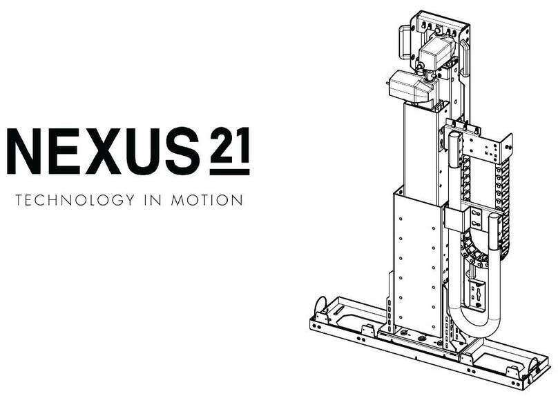
Nexus 21 AL-125 User manual

Lift System Model AL-125
Installation Instructions

2
Contact: [email protected]
Toll Free: (866) 500-5438
Phone: (480) 951-6885
Fax: (480) 951-6879
Revised: 8/16/16
Below is a parts list describing all of the items included with the Model AL-125 Lift System. Before
beginning assembly and installation, please make sure that you have all items included on the list. If any
parts are missing or damaged, please contact Nexus 21. Our contact information is shown at the top of
this page.
Parts List
1. Lift Column 2. Base Mount 3. Load Support Bracket
(22” x 4”) (7” x 3 ½”) (8” x 5 ¼”)
4. Control Box 5. Vertical Stabilizer (2)
(8 ¼” x 3 ¾” x 1 ½”)(26” x 2” x ¾”)
Cables
Motor Cable –Black cable with white, six-pin connector (2 Meters). Use this cable to connect the Lift
Column to the Control Box (using port 1 on the Control Box). Six feet long.
Power Cable –Connects Control Box to power outlet (1 Meter). Three feet long.
RF Cable (only present if you ordered the RF version of the Lift System) –Use to connect the RF Receiver
to the Control Box. Ends have telephone-style (RJ45) connectors. One foot long.
TIP: You may want to install a power strip (not included) in the bottom of your cabinet to plug in the Lift
System Control Box and any other components/appliances in the cabinet.
Hardware Cable Management
6.Two (2) -- #10 x 1 ¾” Flat Head Wood Screw (FHWS) 13.Four (4) -- Wire Clips
7.Four (4) -- #8 x ¾” Flat Head Wood Screw (FHWS) 14.Four (4) -- Zip Ties
8.Eight (8) -- 6mm x 20mm Flat Head Machine Screw (FHMS)
9.Sixteen (16) -- #10 x ¾” Truss Head Wood Screw (THWS)
10. Four (4) -- Lid Catch Brackets w/ (8) 10 x ¾” (THWS)
11.Two (2) –Tapered Pins
12.One (1) -- Allen Wrench –4mm

3
Types of Controls for Nexus 21 Lift Systems
All Nexus 21 Lift Systems come standard with a wireless remote control and receiver. We offer a choice of two
different type of remotes: IR and RF (both of which are explained in detail below). Our standard control type is RF,
so unless you specifically requested the IR version when you made your purchase, you probably received the RF
controls with this Lift System. The method of installation for each type of remote control is slightly different, so
you should now identify which type of remote you have by reading below, and then follow the instructions for that
type of remote.
NOTE: If you will be using the Lift with a home control system (like the ones made by companies such as Crestron
or Control 4) the most common form of control is to WIRE IT DIRECTLY to the relays of your home control system.
This direct-wire method is called Integration by Contact Closure, and is accomplished by using the Backup Control
Switch (Height Limit Switch) that was supplied with the Lift System to connect the Lift to the control unit from your
home control system.
Before You Begin the Installation: Identify Your Control Type
IR (Infrared) –This control option allows you to utilize a 3rd party universal style remote control to raise and lower the TV Lift.
Your universal remote will “learn” the IR codes from the provided IR Handset, which will enable you to control the lift. The
universal remote will then communicate with the “eye” located on the IR Receiver via your 3rd party emitter (or flasher).
Instructions for mounting the IR controls are on page 17. Instructions for setting the TV Lift’s travel limit are on Supplemental
Page B.
NOTE: If you are NOT planning on using a 3rd party Universal Remote, switch to the RF setup. (There is no charge for swapping)
These are the parts included with IR controls:
Contact Closure Hardware IR Receiver IR Handset Height Limit Insert
RF (Radio Frequency) - This system utilizes a wireless remote control handset that sends a radio signal to the RF Receiver. The
radio signal can go through cabinet walls and does not require line-of-sight. Instructions for mounting the RF controls are on
page 17. Instructions for setting the Lift System travel limit are on Supplemental Page B.
TIP: Planning to integrate the TV Lift with your UNIVERSAL REMOTE CONTROL? The RF version of the Nexus 21 controls
won’t do it. Switch to IR.
These are the parts included with RF controls:
Backup Switch RF Receiver RF Handset Height Limit Insert
Integration by Contact Closure –To direct-wire the TV Lift controls to a home control system (Crestron, Control 4,
AMX, etc.) you will use the Back-up Control Switch (Height Limit Switch). You won’t use any Nexus 21 receiver or
handset for this type of control because you will use the handset or control pad that comes with your home
control system. Instructions for setting up the System using Contact Closure are on “Supplemental Page C”.

4
SAFETY INFORMATION
SEVERE PERSONAL INJURY AND PROPERTY DAMAGE CAN RESULT FROM IMPROPER INSTALLATION OR ASSEMBLY. READ THE
FOLLOWING WARNINGS BEFORE BEGINNING.
WARNINGS:
1. Do not use this product for any application other than those specified by Nexus 21.
2. Do not exceed the weight capacity. This can result in serious personal injury or damage to the
equipment. It is the installer’s responsibility to ensure that the total combined weight of all
attached components does not exceed that of the maximum figure stated.
3. Follow all technical specifications and instructions during the installation.
4. Only use attachments/accessories specified by the manufacturer.
5. Close supervision is necessary when this system is being used by, or near, children, or disabled
persons.
6. It is the responsibility of the installer to warn all potential users of the dangers of interfering
with the mechanism during operation.
7. Read all technical instructions fully before installation and use. It is the installer’s responsibility
to ensure that all documentation is passed on the users and read fully before operation.
8. Failure to provide adequate structural strengthening, prior to installation can result in serious
personal injury or damage to the equipment. It is the installer’s responsibility to ensure the
structure to which the Lift System is affixed can support four times the weight of the system.
9. Risk of electric shock. Do not attempt to open the Control Box.
10. To reduce risk of fire or electric shock, do not expose parts to rain or other liquids.
11. Protect the power cord from being walked on or pinched.
12. Keep all documentation.
13. Heed all warnings.
14. Clean only with a dry cloth.
15. Refer all service questions to Nexus 21 if the system does not operate normally.
Nexus 21 disclaims any liability for modifications, improper installations, or installations over the specified
weight range. Nexus 21 will not be liable for any damages arising out of the use of, or inability to use, Nexus 21
products. Nexus 21 bears no responsibility for incidental or consequential damages. This includes, but is not
limited to, any labor charges for the servicing of Nexus 21 products performed by anyone other than Nexus 21.
Nexus 21 intends to make this and all documentation as accurate as possible. However, Nexus 21 makes no
claim that the information contained herein covers all details, conditions or variations, nor does it provide for
every possible contingency in connection with the installation or use of this product. The information contained
in this document is subject to change without prior notice or obligation of any kind. Nexus 21 makes no
representation of warranty, expressed 6 or implied, regarding the information contained herein. Nexus 21
assumes no responsibility for accuracy, completeness or sufficiency of the information contained in this
document.

5
Assembly and Mounting Instructions –You Are Ready to Start
Please perform the following steps, in order:
Step 1: Inventory the Parts List. Carefully inspect all items, making sure you have everything shown in the Parts
List.
Step 2: Seat the “pigtail” cable properly on the bottom of the Lift Column. Take the Lift Column (Part #1) and
find the end with the short black cable (this cable is called the “pigtail”). This end will become the bottom of the
Lift Column. Before you begin to assemble the lift system, you must position the pigtail properly. Look at the
bottom edge of the Lift Column. You will see two square cut-out channels, notched into the steel, one on either
side of the pigtail. Choose one of the cut-outs (it does not matter which one), and seat the pigtail into the cut-out,
using the rubber gasket attached to the cable.
IMPORTANT NOTE: IF THE PIGTAIL CABLE IS NOT PROPERLY SEATED, IT MAY BE DAMAGED WHEN YOU ATTACH THE LOAD
SUPPORT BRACKET (Part #3), CAUSING LOSS OF POWER TO THE LIFT COLUMN.
BEFORE (pigtail is loose) AFTER (pigtail is properly seated)
Step 3: Attach the Base Mount to the Bottom
of the Lift Column. Find the Base Mount (Part
#2). Using the small Allen wrench and four of
the 6mm x 20mm Flat Head Machine Screws,
attach the Base Mount to the bottom of the Lift
Column (the end with the pigtail). The Base
Mount has 8 holes –use the 4 innermost holes,
which will align with the 4 threaded holes at the
bottom of the Lift Column. DO NOT OVER
TIGHTEN!

6
Step 4: Mounting the Load Support Bracket to the back of Box Assembly: Using (8) #10 x ¾” THWS
attach the Load Support Bracket to the back of your Box Assembly. Use two screws towards the top,
middle and bottom of bracket. Now use two screws on the bottom side of the box, to fasten the L-
shaped bracket to the bottom of the box.
NOTE: You may need to use a block between
the bottom of the Box Assembly and the Load
Support Bracket depending on the height of
your Box Assembly.
IMPORTANT NOTE: When installing your
cabinet, make sure it rests 1/8”-1/4” below the
lip edge of the countertop where the lid will sit.
This will make sure our collision detection
software is not engaged from the lift running
into your lid suddenly when operated.
YOU CANNOT ATTACH THE LID TO THE
CABINET; YOU MUST USE OUR TAPERED PINS.
Step 5a: Mounting Lift Column inside of
Cabinet: Position lift column inside cabinet
against the back wall and determine if you need
to block the lift forward. The lift column when
extended should clear the opening of the
cabinet by ½”.
Step 5b: Determine if a platform or block is
needed to raise the lift system up off of the base
of the cabinet. Measure the height of the Box
Assembly by measuring from the bottom of the Lift
Column to the top of your Box Assembly (including
the countertop thickness). Subtract this dimension
from the total height of your cabinet, measured
from the bottom surface of your enclosure to the
countertop surface. If the total height of the Box
Assembly is shorter than the total height of your
cabinet you must build a simple platform (typically
made of wood) to raise the assembly so the top of
your Box Assembly is within ½” of the countertop
surface. Use the formula on the following page to
determine the proper height of the platform

7
Platform Height = (Enclosure Interior Height + Countertop Thickness) –Lift Box Assembly Height
Step 6a: Fasten the Base Mount to the inside
of the cabinet. Using (8) #10 x ¾” THWS mount
the Base Mount to either your platform or the
base of the cabinet.
Step 6b (Optional): Fasten the (4) Steel Corner Brackets to the platform or block the lift is sitting on to
the base of the cabinet. This will provide additional stability to prevent lateral movement from the
platform.
Step 7: Connect the controls. Refer to the wiring diagram on the following page to connect the IR
Controls and Control Box. The diagram for the RF controls can be found on page 9.

8
IF YOU HAVE IR CONTROLS, USE THIS DIAGRAM (for RF Controls, see the following page)
Once you have connected the controls, test the Lift Column as follows:
First, you need to “initialize” the Lift System. If you have already raised the Lift Column, lower it again, since this step must be
performed in the “down” position. Find the Backup Control Switch, which has two triangle-shaped buttons - an UP (with raised
dot) and a DOWN. Press the DOWN button and HOLD IT DOWN for approximately 5 seconds. You should see a slight
movement in the Lift Column. If you do not see the movement, release the Down button, and repeat the process - press and
hold the Down button again for 5 seconds. Once you have seen the slight movement, the Lift System is now functional. Test it
by pressing the Up button (no need to hold the Up button) and the lift will go up. You may let it go to the top, or stop it at any
time by pressing the Down button.

9
IF YOU HAVE RF CONTROLS, USE THIS DIAGRAM (for IR Controls, see the previous page)
Once you have connected the controls, test the Lift Column as follows:
First, you need to “initialize” the Lift System. If you have already raised the Lift Column, lower it again, since this step must be
performed in the “down” position. Find the Height Limit Switch, which has two triangle-shaped buttons - an UP (with raised
dot) and a DOWN. Press the DOWN button and HOLD IT DOWN for approximately 5 seconds. You should see a slight
movement in the Lift Column. If you do not see the movement, release the Down button, and repeat the process - press and
hold the Down button again for 5 seconds. Once you have seen the slight movement, the Lift System is now functional. Test it
by pressing the Up button (no need to hold the Up button) and the lift will go up. You may let it go to the top, or stop it at any
time by pressing the Down button.

10
Step 8: Reinitialize/Reset the lift system. With the lift in the fully retracted position, hold the down
button on the manual back up switch (the grey pad with two triangle buttons) for 3-5 seconds. You
should see the lift column make a slight up and down jog motion; this will let you know the lift system
has successfully been reset. If you do not see the jog motion within the first 3-5 seconds, then release
the down button and try again. Once you have successfully reset the lift system then proceed to the
next step.
Step 9: Extend the lift column while it is
positioned inside the cabinet. Make sure the
lift column has about ½” clearance on the back
side of the column, to ensure lift column does
not run into counter top while extending. This is
the time to make any
necessary adjustments to the position of the lift
column.
IMPORTANT NOTE: Make sure when the lift is
fully retracted, the cabinet rests 1/8” – ¼”
below your lip edge. This will make sure our
collision detection software is not engaged from
the lift running into your lid suddenly when
operated. YOU CANNOT ATTACH THE LID TO
THE CABINET; YOU MUST USE OUR TAPERED
PINS.
NOTE: Do not bump into column while it is in
the “Extended Position,” as the column may tip
over.
Step 10a: Using (6) #8 x ¾” FHWS attach both drawer glides to the back of your Lift Box Assembly to
provide additional stability. Depending on the shape of your lift box assembly the drawer glides may be
mounted on the sides or the back of your Lift Box Assembly.

11
Step 10b: Create two Vertical Stabilizer
support beams on the inside of the cabinet to
attach the bottom half of the Vertical
Stabilizers. Using 2x4 wood beams, create a
structure to fasten each Vertical Stabilizer to.
Step 11: Attach your Lift Box Assembly to the
top of the lift Column. Using (4) 6mm x 20mm
FHMS attached your Lift Box Assembly to the
top of the Load Support Bracket while the lift
fully extended.
NOTE: Depending on the size and design of
your Box Assembly, you may need to create a
notch into the “Lip” of opening of the counter
top, allowing the Vertical Stabilizers to
function properly.

12
Step 12: Using (6) #8 x ¾” FHWS Fasten the
bottom of the Vertical Stabilizers to the
drawer glide support beams you created on
step 6b.
NOTE: Run the lift up and down a few times to
test Vertical Stabilizers fitment. Make
appropriate adjustments at this stage.
Step 13: Attaching Tapered Pins to the
underside of your Lid: Use a 7/32” bit to drill
two ½” holes on the underside of your lid. Use a
Phillips Screwdriver to screw the tapered pins
into the underside of your lid. Once you have
the tapered pins installed on the lid, mark the
same position on the top of your Lift Box
Assembly, where the Tapered Pins will go
through and drill two holes through the top of
your Lift Box Assembly to allow the Tapered
Pins to slide into.

13
NOTE: Step 13 is designed to give the Lid a
“Break-Away” feature, to prevent any finger
injury in case someone has their hand in the
way while the lift is traveling down.
IMPORTANT NOTE: Make sure when the lid
rests 1/8”-1/4” above your cabinet when the lift
is FULLY retracted. This will make sure our
collision detection software is not engaged from
the lift running into your lid suddenly when
operated. YOU CANNOT ATTACH THE LID TO
THE CABINET; YOU MUST USE OUR TAPERED
PINS.
Step 14a: Mounting the Controls: Using (4) #10 x ¾” FHWS mount the Control Box in an accessible
location near the lift column. Make sure this location is accessible when the lift is both extended and
retracted.
Step 14b: Using (2) #6 x ¾” RHWS Step 14c: Using (2) #8 x ¾” FHWS,
located in the RF Kit, mount the RF mount the manual back-up switch
Receiver next to the Control Box. under the counter top lip or a nearby
location.

14
Congratulations your AL-125 Hidden Storage Lift System is now installed!

15
Supplemental Page B: Setting a Height Limit
Please follow this procedure if you would like to limit the distance that your TV Lift extends.
To set your Travel Limit with IR Controls:
If you want the lift system to always go to its full extension, do NOT use the Height Limit Insert. Simply leave it
unplugged and the system will always travel to the full extension. To limit the travel, follow the procedure below:
1. Using the IR Receiver, run the lift
system to the ideal height limit position and stop it
there.
2. With the lift system stopped, plug the
Height Limit Insert into the available
RJ45 port on the Control Box. This will
set the height limit at this position for
both the IR Remote (or 3rd party
universal remote) and the IR Receiver.
3. If the height limit is set at the incorrect
position, remove the Height Limit insert
and repeat the procedure.
To set your Travel Limit with RF Controls:
If you want the lift system to always go to its full extension, do NOT use the Height Limit Insert. Simply leave it
unplugged and the system will always travel to the full extension. To limit the travel, follow the procedure below:
1. Using the Wired Backup Switch, run
the lift system to the ideal height limit
position and stop it there.
2. With the lift system stopped, plug the
Height Limit Insert into the available
RJ45 port on the RF Receiver. This will
set the height limit at this position for
both the RF Remote and Backup Switch.
3. If the height limit is set at the incorrect
osition, remove the Height Limit insert
and repeat the procedure.

16
Supplemental Page C: Connect the Lift to Home Control System

17

18

19

20
866.500.5438
Table of contents
Other Nexus 21 Lifting System manuals

Nexus 21
Nexus 21 CL-65 Series User manual

Nexus 21
Nexus 21 E-550 User manual

Nexus 21
Nexus 21 L-90 User manual

Nexus 21
Nexus 21 L-75ix User manual

Nexus 21
Nexus 21 DL-45b User manual

Nexus 21
Nexus 21 L-85 User manual

Nexus 21
Nexus 21 L-27i User manual

Nexus 21
Nexus 21 L-77i User manual

Nexus 21
Nexus 21 CL-65e User manual

Nexus 21
Nexus 21 XL-85s User manual
Popular Lifting System manuals by other brands

Bruno
Bruno ELECTRA-RIDE SRE-1540 Safety and operating instructions

Ravaglioli
Ravaglioli RAV232 NL manual

Woodpeckers
Woodpeckers QUICKLIFT owner's manual

LSI-Robway
LSI-Robway RCI-1502 HRT instruction manual

Vancare
Vancare VERA-LIFT II B350 operating manual

Jungheinrich
Jungheinrich ECE 220 Standard operating instructions