Autoquip SRP Setup guide

INSTALLATION, OPERATION
AND SERVICE MANUAL
‘SRP’-‘SRPR’-‘SRPRB’
POWERED TURNTABLE
P.O. Box 1058 •1058 West Industrial Avenue •Guthrie, OK 73044-1058 •888-811-9876
•405-282-5200 •FAX: 405-282-3302 •www.autoquip.com
Item # 830SRP Version 2.0
10/2009

TABLE OF CONTENTS
Identification and Inspection 3
Responsibility of Owners / Users 4
SafetySignalWords 5
SafetyPractices 6
Label Identification 9
Specifications 12
Installation Instructions 15
Operating Instructions 18
Routine Maintenance 20
General Maintenance 21
Replacement Parts List 34
Troubleshooting Analysis 38
Warranty 40
IMPORTANT
Please read and understand this manual prior to installation or operation of this
equipment. Failure to do so could lead to property damage and/or serious personal
injury. If any questions arise, call a local representative or Autoquip Corporation at
888-811-9876 or 405-282-5200.
PLANNED MAINTENANCE PROGRAM
A local Autoquip representative provides a Planned Maintenance Program (PMP) for
this equipment using factory-trained personnel. Call a local representative or Autoquip
Corporation at 1-888-811-9876 or 405-282-5200 for more information.
2

IDENTIFICATION & INSPECTION
IDENTIFICATION
PLEASE HAVE THE MODEL NUMBER AND SERIAL NUMBER of the turntable, when
ordering parts or requesting information or service. This information is on the
nameplate attached to the turntable assembly. Replacement parts are available from a
local Autoquip distributor.
INSPECTION
Immediately upon receipt of the turntable, a visual inspection should be made to
determine that it has not been damaged in transit. Any damage found must be noted on
the delivery receipt. In addition to this preliminary inspection, the turntable should be
carefully inspected for concealed damage. Any concealed damage found that was not
noted on the delivery receipt should be reported in writing to the delivering carrier within
48 hours.
The following is a checklist that will aid you in the inspection of this turntable:
1. Examine entire unit for any signs of mishandling or damage. Pay special
attention to the power unit and PUSH BUTTONS.
2. Using an overhead hoist, remove the turntable platform. Thoroughly examine all
base rollers, bolts and hex nuts. Inspect the base frame and turntable, making
sure they have not been damaged during transit. For units that have the controls
mounted and wired inspect wiring for any signs of damage.
3. After inspection, lag the turntable base securely to the floor or lift platform. Using
the overhead hoist, assemble the turntable on the base, and inspect the turntable
operation.
3

RESPONSIBILTY OF OWNERS/USERS
DEFLECTION
It is the responsibility of the user/purchaser to advise the manufacturer where deflection
may be critical to the application.
INSPECTION & MAINTENANCE
The turntable shall be inspected and maintained in proper working order in accordance
with Autoquip’s Operation & Service Manual and with other applicable safe operating
practices.
REMOVAL FROM SERVICE
Any turntable not in safe operating condition such as, but not limited to, missing rollers,
pins, or fasteners, any bent or cracked structural members, cut or frayed electrical
wires, damaged or malfunctioning controls, detents or manual locks, etc. shall be
removed from service until it is repaired to the original manufacturer’s standards.
REPAIRS
All repairs shall be made by qualified personnel in conformance with Autoquip’s
instructions.
OPERATORS
Only trained personnel and authorized personnel shall be permitted to operate this
turntable.
BEFORE OPERATION
Before using the unit, the operator shall have:
•Read and/or had explained, and understood, the manufacturer’s operating
instructions and safety rules.
•Inspected the turntable for proper operation and condition. Any suspect item
shall be carefully examined and a determination made by a qualified person as to
whether it constitutes a hazard. All items not in conformance with Autoquip’s
specification shall be corrected before further use of the turntable.
DURING OPERATION
The equipment shall only be used in accordance with Autoquip’s Operation & Service
Manual.
•Do not overload the turntable.
•Ensure that all safety devices are operational and in place.
MODIFICATIONS OR ALTERATIONS
Modifications or alterations to industrial turntable shall be made only with written
permission of Autoquip. Autoquip does not foresee and does not anticipate
unauthorized modifications, and these changes or alterations are grounds for voiding all
warranties.
4

SAFETY SIGNAL WORDS
SAFETY ALERTS (Required Reading!)
The following SAFETY ALERTS are intended to create awareness of
owners, operators, and maintenance personnel of the potential safety
hazards and the steps that must be taken to avoid accidents. These same
alerts are inserted throughout this manual to identify specific hazards that
may endanger uninformed personnel. Identification of every conceivable
hazardous situation is impossible. Therefore, all personnel have the
responsibility to diligently exercise safe practices whenever exposed to this
equipment.
____________________________________________________________
DANGER!
Identifies a hazardous situation, which, if not avoided, will result in death or
severe personal injury.
_
____________________________________________________________
WARNING!
Identifies a hazardous situation, which, if not avoided, could result in death
or serious personal injury.
CAUTION!
Identifies a hazardous situation, which, if not avoided, may result in minor
or moderate personal injury.
_____________________________________________________________
NOTICE!
Indicates a potentially hazardous situation, which, if not avoided, may result
in property or equipment damage.
5

SAFETY PRACTICES
Read and understand this manual and all labels prior to
operating or servicing the turntable. All labels are provided
in accordance with ANSI Z535.4.
DANGER!
6
The turntable base MUST be lagged securely to the floor or sufficient
structure, or attached to a lift platform (when applicable) before operating
the turntable. An unsecured base could become unstable and cause the
load to shift unexpectedly resulting in serious personal injury or death.
DANGER!
HIGH VOLTAGE!! Disconnect and/or lock out the electrical supply to the
power unit per OSHA regulations prior to any maintenance being performed.
DANGER!
To avoid personal injury or death, do not use the unit in or around an area
where flammable liquids or vapors may be present.
DANGER!
To avoid personal injury or death, do not use the unit near water. If
electrical parts become wet, electrical shock may occur.
DANGER!
Extending the platform length or width beyond the factory limit could cause
the turntable to tip and the load to shift unexpectedly, resulting in personal
injury or death.

SAFETY PRACTICES
WARNING!
NEVER stand, sit, or ride on the turntable! A rotating work surface may
shift position unexpectedly and cause serious personal injury.
WARNING!
All warning and information decals should be in place as outlined in the
“Label Identification” section. If decals are missing or damaged, they
should be replaced with new decals. Contact Autoquip for replacements.
WARNING!
Do not install the turntable in a pit unless it has beveled-toe guards or other
approved toe protection. A shear point can exist which can cause severe
personal injury.
WARNING!
Load the turntable top as evenly as possible to prevent overloading.
Excessive eccentric loading may overstress the turntable structure and
cause the load to become unstable, possibly resulting in serious personal
injury.
7

SAFETY PRACTICES
WARNING!
To avoid personal injury, stand clear of the unit when the turntable is in
motion.
WARNING!
Familiarize yourself with the operator’s manual before operating this
equipment.
NOTICE
Do not continue to depress the “CW” or “CCW switch if the platform does
not turn or if the platform is jammed. To do so may result in permanent
damage to the motor or speed reducer.
NOTICE
Do not operate the turntable if the torque limiter is out of adjustment.
8

1
TOP OF TURNTABLE
BASE
5
4
Figure 1: Decal Placement Diagram
POWERED Turntable Decals
Item No. Qty Description Part No.
1 3 DECAL, CAPACITY : x,000 POUNDS; (2-1/2” x 11”) 36401586
2 2 DECAL, WARNING-NO RIDERS; (2” x 6”) 36403707
3 2 AUTOQUIP LOGO (3” x 7”) 36403220
4 1 AUTOQUIP Serial Number Nameplate (2” x 8”) 36401560
5 2 WIRE CODE Identification (4” x 4”) 36403343
LABEL IDENTIFICATION
9

LABEL IDENTIFICATION
Note: Labels shown here are not actual size, see Figure 1 for
location of label on Turntable.
Figure 2: Capacity Decal (36401586)
Figure 3: WARNING-NO RIDERS Decal (36403707)
Figure 4: AUTOQUIP LOGO Decal (36403220)
10

LABEL IDENTIFICATION
Note: Labels shown here are not actual size, see Figure 1 for
location of label on Turntable.
Figure 5: Serial Number Nameplate (36401560)
Figure 6: WIRE CODE Identification Decal (36403343)
11

‘SRP’ TURNTABLE --“CHAIN & SPROCKET DRIVE”
Standard
Model Rotating
Capacity
Platform
Dimensions
Base
Dimensions
Lowered
Height
Speed
(RPM)
Shipping
Weight
SRP-36-25 2,500 36 x 36 24 x 24 10 3.50 385
SRP-36-40 4,000 36 x 36 24 x 24 10 3.50 385
SRP-36-60 6,000 36 x 36 24 x 24 10 3.50 385
SRP-42-25 2,500 42 x 42 24 x 24 10 3.50 450
SRP-42-40 4,000 42 x 42 24 x 24 10 3.50 450
SRP-42-60 6,000 42 x 42 24 x 24 10 3.50 450
SRP-4248-25 2,500 42 x 48 24 x 24 10 3.50 485
SRP-4248-40 4,000 42 x 48 24 x 24 10 3.50 485
SRP-4248-60 6,000 42 x 48 24 x 24 10 3.50 485
SRP-48-25 2,500 48 x 48 24 x 24 10 3.50 525
SRP-48-40 4,000 48 x 48 24 x 24 10 3.50 525
SRP-48-60 6,000 48 x 48 24 x 24 10 3.50 525
TURNTABLE SPECIFICATIONS
‘SRPR’ ROUND TURNTABLE -- “CHAIN & SPROCKET DRIVE”
Standard
Model Rotating
Capacity
Platform
Diameter
Base
Dimensions
Lowered
Height
Speed
(RPM)
Shipping
Weight
SRPR-36-25 2,500 36 24 x 24 10 3.50 375
SRPR-36-40 4,000 36 24 x 24 10 3.50 375
SRPR-36-60 6,000 36 24 x 24 10 3.50 375
SRPR-42-25 2,500 42 24 x 24 10 3.50 440
SRPR-42-40 4,000 42 24 x 24 10 3.50 440
SRPR-42-60 6,000 42 24 x 24 10 3.50 440
SRPR-48-25 2,500 48 24 x 24 10 3.50 520
SRPR-48-40 4,000 48 24 x 24 10 3.50 520
SRPR-48-60 6,000 48 24 x 24 10 3.50 520
12

SPECIFICATIONS
‘SRPRB’ TURNTABLE -- “RING BEARING DRIVE”
Standard Model Rotating
Capacity
Platform
Dimensions
Base
Dimensions
Lowered
Height
Speed
(RPM)
Shipping
Weight
SRPRB-36-25 2,500 36 x 36 24 x 24 10 1.00 650
SRPRB-36-40 4,000 36 x 36 24 x 24 10 1.00 680
SRPRB-36-60 6,000 36 x 36 24 x 24 10 1.00 705
SRPRB-42-25 2,500 42 x 42 24 x 24 10 1.00 675
SRPRB-42-40 4,000 42 x 42 24 x 24 10 1.00 705
SRPRB-42-60 6,000 42 x 42 24 x 24 10 1.00 730
SRPRB-42-48-25 2,500 42 x 48 24 x 24 10 1.00 700
SRPRB-42-48-40 4,000 42 x 48 24 x 24 10 1.00 730
SRPRB-42-48-60 6,000 42 x 48 24 x 24 10 1.00 755
SRPRB-48-25 2,500 48 x 48 24 x 24 10 1.00 775
SRPRB-48-40 4,000 48 x 48 24 x 24 10 1.00 1000
SRPRB-48-60 6,000 48 x 48 24 x 24 10 1.00 1025
LOAD CAPACITY
1. The load capacity rating is labeled on the top of the turntable platform.
WARNING!
The Turntable should not be overloaded beyond the established
Capacity as damage and/or personal injury may result.
2. When attaching the turntables to other pieces of equipment such as scissors lifts,
remember that the rated capacity of the turntable must not exceed the rated capacity
of the lift, tilter, etc.
13

SPECIFICATIONS
UNBALANCED LOADING — CHAIN & SPROCKET MODELS:
1. All standard turntable capacities assume that the load on the turntable is
uniformly distributed and that the center of gravity of the load is placed
within 10” of the center pin.
2. Standard turntables are not designed to withstand true edge or axle loading.
If edge or axle loading is anticipated, additional turntable support rollers must be
located at the turntable edges for this design. Contact Autoquip Service Department
for questions on turntable loading.
WARNING!
Load the turntable top as evenly as possible to prevent
overloading. Excessive eccentric loading may overstress the
turntable structure and cause the load to become unstable,
possibly resulting in serious personal injury.
UNBALANCED LOADING — RING BEARING MODELS:
1. Ring bearing turntables are designed to withstand eccentric loading. Do not,
however, exceed the edge load rating stamped on the nameplate.
2. Though the platform is designed to withstand offset loading, ensure that the
turntable base is rigidly attached to its mounting surface to prevent tipping of
the load.
14

INSTALLATION INSTRUCTIONS
FLOOR INSTALLATION
1. Make sure floor is clean and level before starting.
2. Place the turntable in the installation area.
3. If the permanent electrical work is not complete, some means of temporary lines with
an on-off device for the power supply should be set up for testing purposes.
15
CAUTION!
When lifting the turntable, do not attempt to pick it up by the
platform; it is attached in the center only and could be damaged.
Pick up the turntable from under the base frame ONLY using a
strap sling.
4. Make temporary electrical connections. Operate the turntable to ensure that rotation
is in the proper direction.
5. If needed, shim to the desired height. DO NOT “spot” shim. Shim the full length of
the base frame. This will prevent the plate from bending under an exceptionally
heavy load.
DANGER!
HIGH VOLTAGE!! – Disconnect and/or lock out the electrical
supply to the power unit per OSHA regulations prior to any
installation or maintenance being performed.
6. The base plate of the turntable has pre-drilled holes for lagging it securely to the
floor. Mark the holes, drill, and install with anchors. Turntables with oversize
platforms have minimum pull out requirements of 2,000 lbs. for each anchor.
7. Make permanent electrical connections and operate the turntable through a few
cycles.

PIT INSTALLATION -- MODELS WITH BEVEL TOE GUARDS MOUNTED ON
SCISSOR LIFT or MOUNTED TO PIT FLOOR.
WARNING!
Do not install the turntable in a pit unless it has a bevel toe
guard or other approved toe protection. A shear point can exist
which can cause severe injury to the foot.
1. Check the pit dimensions. Length and width should be 2" longer (minimum) and 2”
wider (minimum) than the turntable or lift platform, whichever is greater.
2. Check the conduit chase entrance into the pit. The conduit diameter should be 3".
If the permanent electrical work is not complete, some means of temporary lines with
an on-off device for the motor control should be set up for testing purposes.
3. Make sure the pit floor is clean and level before starting. Lower the Lift and
Turntable into the pit and check for proper height. The turntable should be flush with
the pit angle framing. If needed, shim the LIFT BASE FRAME to the desired height.
DO NOT “spot” shim. Shim the ALL (4) Sides of the Lift base frame. This will
prevent the Lift Base from bending under an exceptionally heavy load.
16
CAUTION!
INSTALLATION INSTRUCTIONS
When lifting the turntable, do not attempt to pick it up by the
platform; it is attached only in the center and could be damaged.
Pick up the turntable from under the base frame ONLY using a
strap sling.
4. Make temporary electrical connections. Operate the turntable to ensure that rotation
is in the proper direction.

INSTALLATION INSTRUCTIONS
PIT INSTALLATION -- continued
DANGER!
HIGH VOLTAGE!! – Disconnect and/or lock out the electrical
supply to the power unit per OSHA regulations prior to any
installation or maintenance being performed.
5. The base frame of the turntable has pre-drilled holes for lagging it securely to the
floor. Mark holes, drill, and install with anchors. Turntables with oversize platforms
have minimum pull out requirements of 2,000 lbs. for each anchor.
6. Make the permanent electrical connections and operate the turntable through a few
cycles.
WARNING!
The turntable base MUST be attached securely to the lift
platform before operating the turntable.
NOTE: Turntables that have platform sizes larger than the lifts to which they are
attached must have toe protection, such as beveled-toe guards.
7. A home position limit switch is mounted to the turntable base and wired to the lift
controller. This will ensure that the turntable (in home position) is positioned
exactly over the pit opening before it is lowered into the pit. Home position for the
turntable allows 1” clearance between each side of the turntable and the pit
curb angle.
8. Lower the lift & turntable combination into the pit and check for proper lowered
height.
9. Make the permanent electrical connections and operate the combination through a
few cycles. Check to ensure that the lift will not lower until the turntable platform is in
home position (for four-sided platform).
CLEAN UP
1. Clean up any debris from the area. A clean installation makes a good impression
and creates a much safer environment!
2. Touch-up paint is available from Autoquip for repair of damaged paint surfaces.
17

OPERATING INSTRUCTIONS
18
WARNING!
All DANGER, WARNING, and CAUTION labels and informational
decals and plates must be intact and in place on the unit.
Contact an Autoquip representative if labels are missing or
damaged. See “Label Identification” section of this manual.
WARNING!
Familiarize yourself with this operator’s manual before
operating this equipment.
WARNING!
NEVER stand, sit or ride on the turntable! Personal injury could
result.
WARNING!
Personnel should always maintain a safe operating distance of
at least 36” away from any side of the turntable, any time the
turntable is operated.
1. Press the “CW” button to cause a clockwise rotation of the turntable. When the
“CW” button is pressed, the coil of the motor starter will close the line contact
permitting electrical power to be applied to the motor. The rotating motor shaft is
mechanically coupled to a gear reducer.
CHAIN AND SPROCKET DESIGN
The gear reducer has an output shaft keyed to a drive sprocket. A drive chain
connects the drive sprocket to a large diameter sprocket attached to the underside
of the turntable platform. As the motor rotates, the output shaft turns and rotates the
platform in the clockwise direction.

OPERATING INSTRUCTIONS
RING BEARING DESIGN
1. The gear reducer output shaft is keyed to a custom-fit gear that meshes with and
drives the drive ring of the ring bearing. The drive ring is bolted to and rotates the
turntable platform in the clockwise direction.
2. Press the “CCW” button to cause a counter-clockwise rotation of the turntable.
Pressing the “CCW” button will cause the reversing motor starter to engage and start
the motor. The platform will rotate counter-clockwise.
3. Normally, the platform will continue to rotate as long as the buttons are pushed.
19

ROUTINE MAINTENANCE
WARNING!
Before maintaining the turntable, read & follow the
recommended safety practices in the Safety Practices section.
Failure to follow these safety practices could result in death or
serious injury.
Powered turntables normally will require very little maintenance. However, a routine
maintenance program could prevent costly replacement of parts and/or downtime.
DYNAMIC INSPECTION (Turntable running)
1. Check any unusual noise when it occurs. Determine the source and correct as
necessary.
2. Check for chain tightness and lubricate every 90 days (chain & sprocket models).
DANGER!
HIGH VOLTAGE!! – Disconnect and/or lock out the electrical
supply to the power unit per OSHA regulations prior to any
installation or maintenance being performed.
ROUTINE STATIC INSPECTION
1. Check for unusual wear on the rollers. Make sure they are free to rotate and that
there is desirable clearance between the rollers and the platform.
2. Check that all platform retention hardware is in place and secure.
3. Check broken or cracked welds.
4. Check that all lag down anchors are in place and secure.
5. Check that the chain connections are secure and that all keepers are in place.
6. Check that all electrical connections and wiring are undamaged and secure.
7. Check the oil level every 90 days in the: gear reducer & air lubricator and add
appropriate oil when needed. Contact Autoquip Service Department for
oil information.
8. Check for unusual wear between worm gear & drive shaft (Ring Bearing Models).
9. Grease Ring Bearing and check oil level in gear reducer every 90 days. Contact
Autoquip Service Department for grease & oil information.
20
GENERAL MAINTENANCE
This manual suits for next models
2
Table of contents
Popular Turntable manuals by other brands
Ortofon
Ortofon AS-212R user guide
tri-art audio
tri-art audio P Series user manual
Dual
Dual ASP 125 Service manual
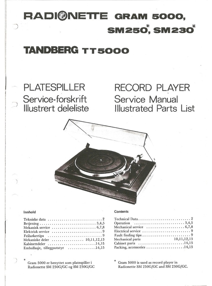
Radionette
Radionette Tandberg TT 5000 Service manual
Pro-Ject Audio Systems
Pro-Ject Audio Systems Pro-Ject RPM 10 Instructions for use
Audio Technica
Audio Technica AT-LP2D-USB Installation and operation guide
