AUTOSCALER AW25C User manual

1
Table of Contents
Tabletop Model (AW25C/AW30C)
Tabletop Model (AW25C/AW30C) Direcons for Use ............................. Pg 3
Warranty .................................................................................................. Pg 2
Features ................................................................................................... Pg 4
Responsibilies ........................................................................................ Pg 4
Special Precauons .................................................................................. Pg 4
Infecon Control ...................................................................................... Pg 5
Introducon ............................................................................................. Pg 6
Electronic Generator and Water System ................................................. Pg 6
Handpiece Assembly ................................................................................ Pg 7
Electrical Requirements ........................................................................... Pg 7
Installing the Handpiece Assembly .......................................................... Pg 8
Installaon and Operaon ....................................................................... Pg 8
Shut Down Procedure ............................................................................ Pg 10
Troubleshoong..................................................................................... Pg 10
Scaling Techniques ................................................................................. Pg 11
Ultrasonic Scaler Inserts......................................................................... Pg 26
Build-In Model (AW25BI/AW30BI)
Build-In Model (AW25BI/AW30BI) Direcons for Use ........................... Pg 12
Warranty .................................................................................................. Pg 2
Features ................................................................................................. Pg 13
Build-In Model Installaon Guide .......................................................... Pg 14
Responsibilies ...................................................................................... Pg 17
Daily Procedures .................................................................................... Pg 17
Special Precauons ................................................................................ Pg 17
Infecon Control .................................................................................... Pg 18
Introducon ........................................................................................... Pg 18
Electronic Generator and Water System ............................................... Pg 19
Handpiece Assembly .............................................................................. Pg 19
Electrical Requirements ......................................................................... Pg 20
Installaon and Operaon ..................................................................... Pg 20
Shut Down Procedure ............................................................................ Pg 22
Troubleshoong..................................................................................... Pg 22
Scaling Techniques ................................................................................. Pg 23
Brief Layout of the Build-In Style AUTOSCALER® ................................... Pg 24
Ultrasonic Scaler Inserts......................................................................... Pg 26
2
AUTOSCALER® WARRANTY INFORMATION
For All Models
Proof of purchase such as a copy of ORIGINAL BILL OF SALE must be
submied to obtain warranty service. Warranty DOES NOT include
Shipping and Handling charges in either direcon.
South East Instruments, LLC (hereaer SEI) subject to the terms and
condions herein below expressly set forth in Paragraphs "1" through "4"
HEREBY WARRANTS that it will repair the AUTOSCALER® Ultrasonic
Scaler which proves defecve by reason of improper workmanship and or
materials.
1. SIX YEAR Parts and Labor coverage on circuit boards, and TWO YEAR
Parts and Labor coverage on all other components of the
AUTOSCALER®.
2. ORIGINAL PURCHASER: This warranty is limited to the original
purchaser of the unit. When requesng warranty service, SEI needs a
RETAIL sales receipt to VALIDATE sales/installaon date.
3. PROPER DELIVERY: The unit must be shipped, Freight Prepaid, or
delivered to SEI to render the services provided hereunder in either
its original package, or a similar package aording an equal degree of
protecon. Warranty does not include shipping and handling back to
the customer.
4. UNAUTHORIZED REPAIR, ABUSE, ETC.: The unit must not have been
previously altered, repaired or serviced by anyone other than SEI or a
qualied technician. To render such service, the serial number on the
unit must not have been altered or removed. The unit must not have
been subjected to accident, misuse, abuse, or operated contrary to
the operang instrucons. Handpiece assembly is not warranted if
subjected to abuse from excessive pulling/stretching, debris and/or
chemical accumulaon from water supplies. Water system is not
warranted by failure due to debris, and/or chemical deposits from
water supplies or added medicinal soluons. Foot switch is not
warranted by failure due to tampering, or operaon/storage in a wet
environment.
EXCEPT TO THE EXTENT PROHIBITED BY APPLICABLE LAW, NO OTHER
WARRANTIES, EXPRESSED OR IMPLIED, INCLUDING WARRANTIES OF
MERCHANTABILITY, AND FITNESS FOR A PARTICULAR PURPOSE, SHALL AP-
PLY TO THIS EQUIPMENT. DAMAGES ARE LIMITED STRICTLY TO REPAIR OR
REPLACEMENT OF PARTS. UNDER NO CIRCUMSTANCES SHALL SEI BE LIABLE
FOR INCIDENTAL OR CONSEQUENTIAL DAMAGES RESULTING FROM THE USE
OF THE EQUIPMENT, AND SEI NEITHER ASSUMES NOR AUTHORIZES ANY
REPRESENTATIVE, OR OTHER PERSON TO ASSUME FOR IT ANY OBLIGATION
FOR LIABILITY OTHER THAN SUCH AS IS EXPRESSLY SET FORTH HEREIN.
3
®
DIRECTIONS FOR USE
For Tabletop Models
AW25C and AW30C
ULTRASONIC SCALER/PROPHYLAXIS UNIT
AUTOSCALER® DIRECTIONS FOR USE
ALL RIGHTS RESERVED
Form #QP272-G, Rev. September 2020
Documents Aected: AW25C, AW30C; FM119, MP104
THE AUTOSCALER® ULTRASONIC SCALER IS A PRESCRIPTION DEVICE AND IS
INTENDED FOR USE ONLY BY LICENSED DENTAL PRACTITIONERS.
FEDERAL LAW RESTRICTS THE DEVICE TO SALE BY OR ON THE ORDER OF A
LICENSED PRACTITIONER.
4
FEATURES
The AUTOSCALER® is designed for Dental Prophylaxis Treatment when
used with the appropriate Cavitron® brand – Series: “P”, “SLIMLINE”™,
“FSI”™ or “TFI”™ 25,000Hz series inserts*. If you have purchased the
AUTOSCALER® 30,000Hz model you must use 30,000Hz frequency
inserts. Inserts are not interchangeable. The AUTOSCALER® is
acceptable for use in scaling and cleaning surfaces of teeth in
conjuncon with other prophylacc measures.
AUTOSCALER® is a registered trademark of South East Instruments,
LLC.
Recommendaons by the manufacturer contained within this
instrucon booklet are recommendaons only. Other opons may be
available or mandated by the professional or regulang agencies.
RESPONSIBILITIES
It is the responsibility of the dental professional using this device to be
fully trained in the proper use of ultrasonic scalers. The operator must
be observant of possible changes in performance during a procedure
and immediately disconnue use of this product, and determine the
cause of such changes in performance before connuing dental
procedures. Performance varies slightly between manufacturers of
ultrasonic scalers, so the operator must become familiar with the
operang parameters, and adjustments of this parcular device.
Performance varies between Ultrasonic Inserts due to the style insert,
model insert, and from the age and/or modicaons of the insert.
SPECIAL PRECAUTIONS
The exible Water Input Hose is subject to deterioraon by
aging, chemicals in the water supply, excessive exing, and
pressure uctuaons. As an added precauon, the water supply
should be turned OFF at the end of the day. REMEMBER to turn
the water back ON prior to use the next day.
The AUTOSCALER® should NOT be used for restorave dental
procedures involving the CONDENSATION OF AMALGAM.
*Cavitron®, SLIMLINE™, FSI™, and TFI™ are registered trade marks of Dentsply Sirona

5
The AUTOSCALER® should NOT be used on or near anyone ed
with a CARDIAC PACEMAKER.
Do not remove the cover from the unit. There are NO user
serviceable parts inside. Allow only qualied technicians to service
your AUTOSCALER®.
DO NOT AUTOCLAVE the detachable HANDPIECE assembly. A
Federally approved non-immersion WATER BASED cold
sterilizaon soluon may be used on the detachable handpiece
assembly. However, DO NOT get sterilizaon soluons on the
electrical contacts of the Handpiece CONNECTOR as this will cause
oxidaon, and a poor electrical connecon. DRY ALL SURFACES
with clean air or clean paper towels.
If your unit is le ON, and the footswitch is accidentally depressed
while unaended, this will permanently damage your unit. Be sure
nothing is touching the operatory air foot switch when not in use.
INFECTION CONTROL
Manufacturer recommends that all operators of this ultrasonic
unit wear at least one pair of surgical rubber gloves, and for extra
prevenon wear double pairs of gloves to isolate the operator
from infecon, and cross contaminaon of other paents.
It is recommended that complete eye and face protecon be used
during the use of this unit to prevent saliva spray from being
inhaled, and from entering the operator’s eyes.
Operator should be careful not to puncture the skin with any
insert p containing saliva from paents. Insert ps should be
sterilized aer each paent according to the insert manufacturer’s
instrucons.
DO NOT AUTOCLAVE the detachable HANDPIECE assembly. A
Federally approved non-immersion WATER BASED cold
sterilizaon soluon may be used on the detachable handpiece
assembly. However, DO NOT get sterilizaon soluons on the
electrical contacts of the Handpiece CONNECTOR as this will cause
oxidaon, and a poor electrical connecon. DRY ALL SURFACES
with clean air or clean paper towels.
Manufacturer recommends the use of a disposable handpiece
sleeve/barrier that keeps contaminaon from geng on the
handpiece assembly. Dispose of sleeve/barrier aer each paent.
Ask your local dealer for HIGH SPEED LONG sleeve/barrier.
6
INTRODUCTION
Your South East Instruments AUTOSCALER® Ultrasonic Scaler is a
precision engineered instrument, constructed with the nest of
materials, and requiring no special maintenance. By taking the
following precauons your unit will give you many years of service.
1. Do not place unit on or near any source of heat.
2. Clean the outer surfaces of the AUTOSCALER® with a Federally
approved non-immersion WATER BASED cold sterilizaon soluon.
Dry immediately with clean air or clean paper towels.
3. Unit should be located where a normal amount of air will circulate
freely around the case when in use.
4. The handpiece and Quick Connector are very strong but care
should be taken NOT TO PULL with excessive force.
Basically, the unit consists of three major components: the electronic
generator, the water system, and the handpiece assembly.
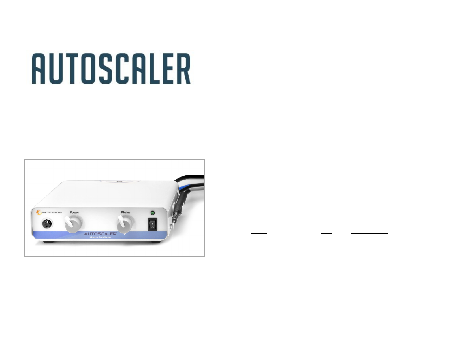
ELECTRONIC GENERATOR AND WATER SYSTEM
The electronic generator produces the frequency and the power to
acvate a wide variety of interchangeable Cavitron® insert ps. The
water system provides precise control over the water lavage ow
which serves to wash debris from the work area, and to cool the
laminaons of the insert p. The following controls are found on the
front panel of your AUTOSCALER®:
Toggle Switch : To turn unit On and O.
Indicator L.E.D. Lamp (above the switch) which lights when the
Toggle Switch is set to the ON-I posion, indicang the unit is
ready for operaon.
Power Control Knob: The Linear Power Control knob adjusts the
output power to the insert p. The blue
shaded area is for use when using
Cavitron® SLIMLINE™, FSI™ or modied
Periodontal inserts. It is recommended
the Power not be set higher than 12:00
even if no mist appears at the p.
Slimline inserts do not easily mist
the water, and are very fragile at higher
power sengs. FOLLOW INSERT
MANUFACTURER'S COMPLETE
INSTRUCTIONS.

7
Water Control Knob: For adjusng the ow of water to the
handpiece and insert p. To obtain the necessary water ow of at
least (18cc - 30cc/+/minute) turn the WATER KNOB clockwise.
HIGHER water ow to the RIGHT, and LOWER water ow to the
LEFT.
Handpiece Panel Receptacle: Accepts the male side of the
Handpiece connector with lock ring.
HANDPIECE ASSEMBLY
The handpiece assembly is used to accept Cavitron® interchangeable
insert ps. It is connected to the AUTOSCALER® front panel by a Quick
Connector. The open end of the handpiece will accept all Cavitron®
brand: "P", "TFI™", “SLIMLINE™” or “FSI™” style 25,000Hz (25K)
inserts. If you ordered a 30,000Hz (30K) model AUTOSCALER®, you
must use the shorter (30K) frequency insert ps.
30K ps measure (Shorter style approx. 6.25 inches long)
25K ps measure (Longer style approx. 7.25 inches long)
(25K) inserts will NOT work in your 30K unit.
(30K) inserts will NOT work in your 25K unit.
Inserts are extremely FRAGILE. If one is dropped, bent, or scratched it
WILL NOT cavitate (i.e. will not funcon) or funcon by operang at a
higher than normal temperature, and should be replaced immediately.
Insert ps should be rounely replaced according to insert
manufacturer's recommendaons.
ELECTRICAL REQUIREMENTS
A GROUNDED wall receptacle is required supplying a voltage range
of 110-125 volts 50/60 Hz A.C. If a 3 to 2 prong adapter is used, the
ground wire MUST be connected to the base plate screw. Have an
electrician test your outlet for correct wiring polarity and a safe
ground. Do not assume the ground is complete. If you plug the
AUTOSCALER® in a GFI (Ground Fault Interrupt ) outlet it may trip the
socket due to the high sensivity of the socket. If this occurs plug the
AUTOSCALER® into a non-GFI socket.
*Cavitron®, SLIMLINE™, FSI™, and TFI™ are registered trade marks of Dentsply Sirona
8
INSTALLING THE HANDPIECE ASSEMBLY
1. Align the electrical contacts of the MALE connector with the same on
the FEMALE panel connector.
2. Gently insert the connector. It should slide in with very lile eort. If
the connector does not align, DO NOT force it. Turn the CONNECTOR
BODY in either direcon unl the connector correctly aligns and goes
in.
3. Once the connector has been completely inserted, screw the OUTSIDE
LOCK RING to the RIGHT with light nger pressure unl it stops. DO
NOT over ghten the lock ring, be careful not to cross thread the lock
ring.
4. To remove the connector, unscrew the lock ring to the le, and gently
pull outward grasping the enre connector body.
INSTALLATION AND OPERATION
DO NOT use your AUTOSCALER® unl all of the following steps have been
completed.
1. Upon receipt of your unit carefully unpack it and see that the Toggle
Switch is in the OFF-O posion.
2. The Water Control Knob should be in the HIGH posion by turning
the water control knob all the way to the RIGHT.
3. Set the Power Knob all the way to the LEFT in the LOW posion.
4. Plug the male Water Quick Release Valve water connector into the
Dental operatory or have a plumber install a SHUT OFF style FEMALE
connector. A minimum of (20 P.S.I.) water input pressure and a
maximum of (60 P.S.I.) is needed from the operatory for proper oper-
aon of the AUTOSCALER®. It is recommended that water line ltra-
on be used to remove larger parcles before entering the scaler.
5. Plug the power cord into the wall (see electrical requirements). Press
the toggle switch to the ON-I posion. The L.E.D. light above the
switch should be ON (“I” posion).
6. Select an insert. Moisten the rubber O-RING before inserng into
the handpiece. While holding the handpiece UPRIGHT place the
insert in the open end of the handpiece and with a gentle PRESS and
TURN moon, snap the insert in fully. DO NOT force the insert.
7. Manufacturer recommends the use of a disposable handpiece
sleeve/barrier be used over the handpiece assembly. Place the
sleeve/barrier over the handpiece. While holding the sleeve/
barrier in place, puncture the insert through the plasc at the open
end of the handpiece, and snap the insert in fully. Dispose of
sleeve/barrier aer each paent.
8. Due to atmospheric exposure and exposure to sterilizaon soluons
the O-RING on the insert p may become swollen, brile, or crack,
and require replacement.

9
9. Hold the handpiece in a VERTICAL upright posion and step on the
foot switch. Within 10-15 seconds water should come out of
10. Inserts and handpiece will burn in 45-60 seconds in the absence of
water. A (18cc—30cc/+/min) ow is the normal ow range, and
necessary at all mes. NEVER touch the Cavitang/Vibrang end of the
insert p to any esh such as the cheek, tongue, or gums unless
performing special periodontal procedures. This will cause a FRICTION
BURN to the paent. Always keep the insert in moon, do not rest the
handle or insert on the lips during a procedure. The insert p should
touch primarily the calculus on the tooth surface and NOT the enamel
of the tooth surface.
11. Allow the air bubbles to escape for about 10-20 seconds. Turn the
POWER KNOB to the RIGHT in the Medium posion and the insert p
should Cavitate/Vibrate with a strong mist. Turn the water knob to
the right if there is no mist or weak misng.
12. The applicaon of the power knob is for controlling the Output Power
to the insert p in a smooth linear acon. The operator can select the
EXACT power needed for cleaning. Set power knob LOW (Le Direcon)
to MEDIUM (Center) for cooler handpiece/insert temperature.
13. The high power seng is for applicaons where an excessive amount
of calculus is built up. The Low power seng can be used for
periodontal Subgingival cureage and root planing procedures. Most
scaling should be done only on the LOW to MEDIUM power seng.
14. If SLIMLINE™, FSI™ or Modied Periodontal inserts are used set the
POWER Knob in the BLUE shaded area. This power level is designed to
be used with these fragile specialty inserts. Inserts may give a drip and
mist combinaon, this is normal for these inserts. This is actually
preferred by most Periodontal professionals due to the water drip
being ultrasonically acvated within 0.5mm of the p assisng in killing
plaque.
UNIT IS NOW READY FOR USE
the open end of the handpiece IF NOT, QUICKLY
turn WATER KNOB clockwise to get water ow,
some air will escape at the same me. This step is
IMPORTANT because trapped air will cause HOT
SPOTS (usually noted by a loud screeching sound)
which can aect the performance of the
AUTOSCALER® or permanently damage the
handpiece assembly.
10
SHUT DOWN PROCEDURE
1. IMPORTANT: At the end of the work day turn o the water supply to
the AUTOSCALER® by disconnecng the QUICK RELEASE VALVE water
connector or shung o the main operatory water supply. This will
prevent water damage to your oce by aging or unseen defects in
water lines that could rupture under connuous pressure.
2. Purge water from the AUTOSCALER® water hose and plumbing system
at the end of the day.
• Connect the QUICK RELEASE VALVE water connector to an air
source.
• Turn the Power Knob to the Le to the lowest seng and the
Water Knob to the Right to the highest seng.
• Press the Toggle switch to the ON-I posion
• Hold the handpiece assembly over a basin and step on the
footswitch and run the scaler just unl all water is expelled via
the handpiece assembly.
3. Press the Toggle Switch to the OFF-O posion. The light should be o.
4. Reconnect the QUICK RELEASE VALVE water connector to the water
supply.
5. REMEMBER to reconnect (turn on) the water the next day before
usage.
TROUBLESHOOTING
If the unit does not funcon, proceed with the following:
1. If the power L.E.D. light above the switch is not lit, replace the FUSE
on the rear panel with a "LITTLE FUSE" 2 amp Fast Blow style. If the
fuse opens again DO NOT aempt to replace the fuse as this indicates
a serious condion that must be examined by the factory. Call for
service (800) 648-9445.
2. Check the plug. Is it all the way in the receptacle?
3. Try another insert. Make sure it is the correct frequency, 25K or 30K,
depending on your model. Each model has a frequency (25K or 30K)
label on the cover and the frequency is also indicated on the serial
number plate located on the back of the device. The most common
mistake when purchasing a new unit is selecng the wrong
frequency insert.
4. If water ow is insucient, check water pressure at the operatory for
minimum of 20 P.S.I. The Insert Water slot could be clogged with
debris. Try another insert. See if the QUICK RELEASE VALVE water
connector is locked fully in place.
5. If the handpiece handle or insert operates HOT: REDUCE POWER
LEVEL and INCREASE WATER FLOW.
11
6. NEVER touch the Cavitang/Vibrang end of the insert p to any
FLESH such as the cheek, tongue, or gums unless performing special
periodontal procedures, this will cause a fricon burn to the paent.
Always keep the insert in moon. Do not rest the handle or insert on
the lips during a procedure. The insert p should touch PRIMARILY the
calculus on the tooth surface, and NOT the enamel of the tooth
surface.
7. If the AUTOSCALER® stops funconing or is intermient when the
handpiece cord is moved, this means a wire in the handpiece cord is
broken and must be immediately repaired or replaced. DO NOT
connue to press the foot switch as there is a possibility the internal
circuit safety fuse may blow and require replacement by a qualied
technician.
8. If handpiece service is needed: Turn the unit OFF. Carefully unscrew
the outer lock ring of the handpiece assembly to the LEFT and gently
unplug the handpiece from the front panel. You can call your dealer
for assistance or SEI at (800) 648-9445 for further instrucon.
9. If a humming or high pitch sound is noted from the console during
roune use, this is a normal circuit resonance which will change as the
POWER control knob is adjusted up and down, and will not aect the
performance of your AUTOSCALER®.
10. Slimline™ and FSI™ inserts are extremely thin and FRAGILE. During
normal use the water may not mist like standard inserts (i.e. like a
TFI#10 curee p); however, the cleaning acon is just a eecve. It is
recommended the Power knob be set in the LOW posion (Blue area)
to assure best performance.
Call your dealer or customer service at South East Instruments for
further instrucons at (800) 648-9445 to help you with quesons and
what to do next.
SCALING TECHNIQUES
Scaling techniques are at the opon of the professional using this
instrument.
1. Excessive pressure is not necessary with the AUTOSCALER®. Use a
gentle, rapid moon with small overlapping strokes, being certain that
the insert is at a 15 degree angle to the tooth surface.
2. If paent Hypersensivity is noted, you should lighten pressure on the
handpiece, Reduce the Power Level or move from the sensive tooth
to another and return to the tooth later. If sensivity persists, switch
to a hand instrument.
12
®
DIRECTIONS FOR USE
For Build-In Retrot Models
AW25BI and AW30BI
ULTRASONIC SCALER/PROPHYLAXIS UNIT
AUTOSCALER® DIRECTIONS FOR USE
ALL RIGHTS RESERVED
Form #QP272-G, Rev. September 2020
Documents Aected: AW25BI, AW30BI; FM124, MP105
THE AUTOSCALER® ULTRASONIC SCALER IS A PRESCRIPTION DEVICE AND IS
INTENDED FOR USE ONLY BY LICENSED DENTAL PRACTITIONERS.
FEDERAL LAW RESTRICTS THE DEVICE TO SALE BY OR ON THE ORDER OF A
LICENSED PRACTITIONER.
13
FEATURES
The AUTOSCALER® is designed for Dental Prophylaxis Treatment when
used with the appropriate Cavitron® brand – Series: “P”, “SLIMLINE”™,
“FSI”™ or “TFI”™ 25,000Hz series inserts*. If you have purchased the
AUTOSCALER® 30,000Hz model you must use the 30,000Hz frequency
inserts. Inserts are not interchangeable. The AUTOSCALER® is acceptable
for use in scaling and cleaning surfaces of teeth in conjuncon with other
prophylacc measures.
This Build-In style AUTOSCALER® unit is NOT intended for user/owner
install. It requires a technician familiar with dental operatory Air and
Water circuitry. This product needs installaon of the following for
proper operaon:
1. The Handpiece Assembly. Roung of 18 gauge wires through the
dental operatory to the AUTOSCALER® console.
2. Water delivery/control for the unit. The AUTOSCALER® does not come
equipped with any water control devices/controllers, however proper
water ow is mandatory for the operaon of this product. See oper-
ang instrucons later in this booklet for proper operang parameters.
3. Power Control Pot. Roung of (2) 18 gauge wires through the dental
operatory to the AUTOSCALER® console.
4. An independent Air Source to acvate the AUTOSCALER® supplied by
the dental operatory (i.e. independent air/water block with auto
holder). The air supply must relieve to zero pressure aer each
depression of the main air rheostat.
AUTOSCALER® is a trade mark of South East Instruments, LLC.
Recommendaons by the manufacturer contained within this instrucon
booklet are suggesons only. Other opons may be available or mandated
by the professional or regulang agencies.
The source of the air signal, water supply, and installaon are not the
responsibility of South East Instruments, LLC. Any damage to the
AUTOSCALER®, PATIENTS or DENTAL OPERATORY resulng from improper
installaon or conguraon is the sole responsibility of the installing dealer
or technician. The AUTOSCALER® BUILD-IN Models AW25BI or AW30BI are
sold as component devices that require further installaon by a party
appointed by the end user. If the installing technician or end user is in doubt
as to correct installaon procedures they should stop immediately and call
South East Instruments, LLC for further instrucons at (800) 648-9445 before
aempng to proceed with the installaon.
*Cavitron®, SLIMLINE™, FSI™, and TFI™ are registered trade marks of Dentsply Sirona
14
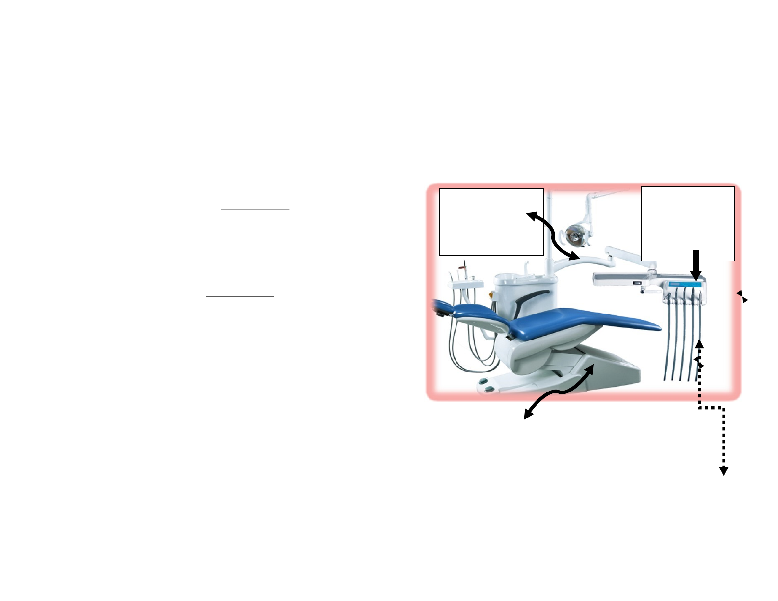
BUILD-IN MODEL INSTALLATION GUIDE
This GUIDE is to assist the technician. Most dental chairs ulize similar
conguraons. It is the responsibility of the technician to properly
install and conrm proper funcon with the parcular chair
manufacturer conguraon.
DO NOT aempt to install this device without an independent air/
water block with automac handpiece holder. The technician must
be familiar with dental chair air water logic to correctly install this
device. Most installaons convert the exisng 3rd or 4th air/water
high or low speed drill block for this purpose.
There MUST be (4) 18
GAUGE wires running from
the juncon box,
THROUGH THE ARM to the
tray for handpiece and power
control connecons.
The handpiece and
(POWER CONTROL)
are mounted on the (tray).
An (AUTOMATIC
HOLDER) must be used
for the Autoscaler®
handpiece.
The AUTOSCALER® (CONSOLE) is mounted under the chair or
(JUNCTION BOX). NOTE: If the AUTOSCALER® receives an air signal
from another source (i.e. high speed or low speed drill) it can damage
the device and the handpiece assembly.
WATER FLOW to the handpiece is received from the air/water block (NEEDLE
VALVE). When the main air rheostat is pressed, an air signal is sent to the
AUTOSCALER® console to (cavitate the insert) and the air/water block opens to
release water ow to the handpiece. Quickly adjust the water knob to get
water owing.
15
If no water is present:
The handpiece will become overheated and damage the
handpiece within 45-60 seconds.
Do not acvate the AUTOSCALER® without an insert in the
handpiece. This can cause the internal coil to overheat and
damage the handpiece.
Connecons on the console are:
Front Panel - Connector for handpiece and power control wires.
Black and Red wires are for the HANDPIECE. There is NO
POLARITY for the handpiece wires.
2 Yellow wires are for the POWER CONTROL. There is NO
POLARITY for the power control wires.
ALL WIRES MUST BE 18 GAUGE. THINNER WIRE WILL RESULT IN
THE WIRE HEATING AND LOSS OF POWER and/or TUNING.
Rear Panel - Air input line yellow 1/16” to receive the
independent acvaon signal (20 to 60 PSI Range) from the
dedicated air/water block (chip/drive air). BE SURE when the
AUTOSCALER® handpiece is picked up from the automac
holder, no other air handpieces are acvated. Verify that when
a high or low speed drill is removed from the automac holder
the AUTOSCALER® does not receive an air signal and acvate. If
so, it will permanently damage the AUTOSCALER®. Only ONE
handpiece should acvate at a me when picked from the
holder.
Rear Panel - AC power plug on rear panel.
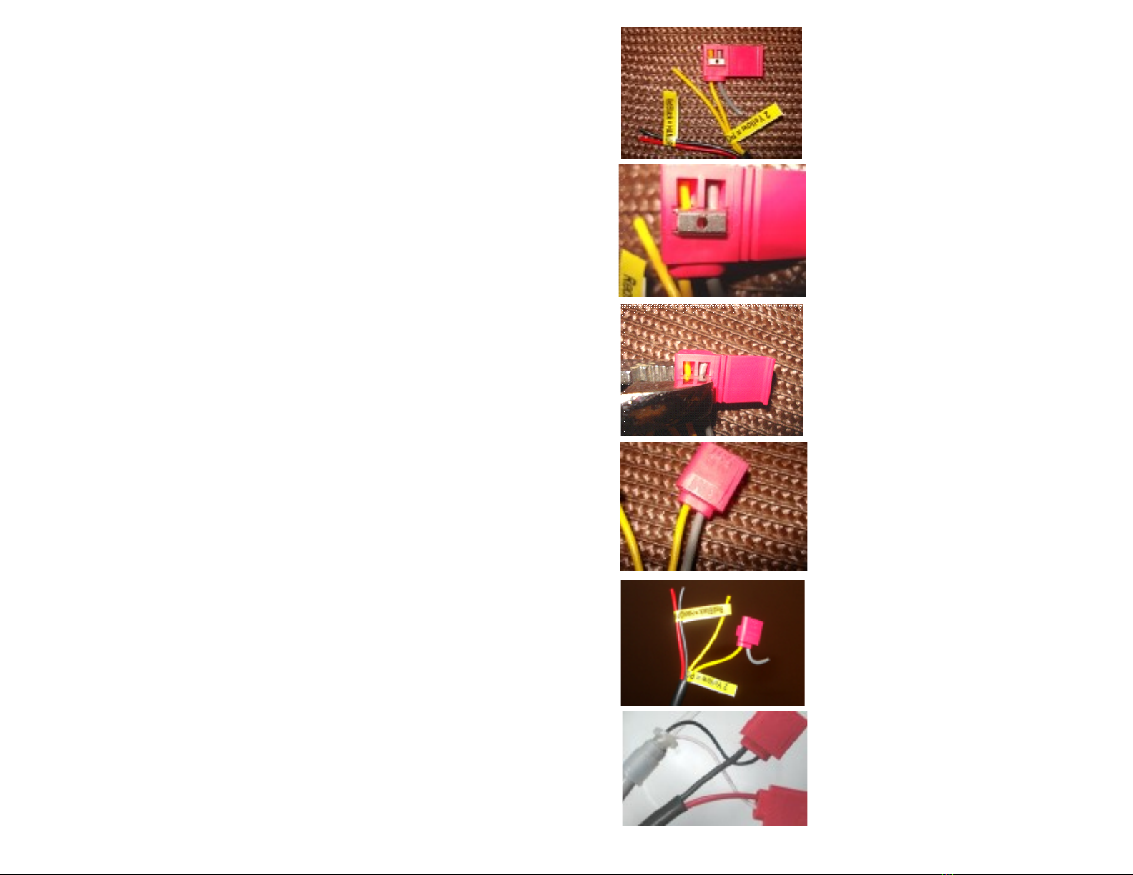
Enclosed: (10) Scotchlok 557 wire connectors to complete your wire
connecons. Only 8 are needed and two are spares. Tools needed
are pliers to compress and secure the Scotchlok 557 connector. The
example on the following page shows one connecon for the power
control yellow wires connecng to the exisng wires from the
dental unit arm.
The exisng wires in the dental chair arm MUST be 18 gauge in
order not to overheat the wires and cause tuning and/or power
issues.
16
Example shows hookup of one of the 4
wires on the console side in the juncon
box. Insert one yellow wire into the
connector and one of the wires from the
chair arm.
Make sure both wires are inserted fully.
Take your pliers and pinch the metal
clamp fully unl it clicks and is at with
the plasc.
Fold over the plasc lid unl it locks. Repeat
process for other connecons. If the
Scotchlok 557 connector fails to complete
the connecon, the technician MUST
SOLDER the wires and apply a UL or CSA
approved heat shrink. DO NOT twist, tape or
use wire nuts for the connecons.
On the tray side repeat the same
method for the handpiece and power
control wires.
The handpiece wires are thinner and
care should be noted that the wires are
fully inserted and align straight in the
metal clamp blades to make a secure
connecon.
Power Control Wires
Handpiece Wires
Wires
Inserted Fully
Metal Clamp

17
RESPONSIBILITIES
It is the responsibility of the dental professional using this device to be
fully trained in the proper use of ultrasonic scalers. The operator must
be observant of possible changes in performance during a procedure
and immediately disconnue use of this product and determine the
cause of such changes in performance before connuing dental
procedures. Performance varies slightly between manufacturers of
ultrasonic scalers, so the operator must become familiar with the
operang parameters, and adjustments of this parcular device.
Performance varies between Ultrasonic Inserts due to the style insert,
model insert, and from the age and/or modicaons of the insert.
DAILY PROCEDURES
At the end of the work day shut o ALL operatory Air and Water
supplies. This will prevent water damage to your oce by aging or
unseen defects in water lines that could rupture under connuous
pressure.
REMEMBER to turn back on the next day before usage.
SPECIAL PRECAUTIONS
As an added precauon, the water supply should be turned OFF at
the end of the day. REMEMBER to turn the water back ON prior to
use the next day.
The AUTOSCALER® should NOT be used for restorave dental
procedures involving the CONDENSATION OF AMALGAM.
The AUTOSCALER® should NOT be used on or near anyone ed
with a CARDIAC PACEMAKER.
Do not remove the cover from the unit. There are NO user
serviceable parts inside. Allow only qualied technicians to service
your AUTOSCALER®.
Do not remove the internal air restrictor. This is a safety device
and must not be removed.
DO NOT AUTOCLAVE the HANDPIECE assembly. A Federally
approved non-immersion WATER BASED cold sterilizaon soluon
may be used on the handpiece assembly. DRY ALL SURFACES with
clean air or clean paper towels.
If your unit is le ON, and the footswitch is accidentally depressed
while unaended, this will permanently damage your unit. Be sure
nothing is touching the operatory air foot switch when not in use.
18
INFECTION CONTROL
Manufacturer recommends that all operators of this ultrasonic
unit wear at least one pair of surgical rubber gloves, and for extra
prevenon wear double pairs of gloves to isolate the operator
from infecon, and cross contaminaon of other paents.
It is recommended that complete eye and face protecon be used
during the use of this unit to prevent saliva spray from being
inhaled, and from entering the operator’s eyes.
Operator should be careful not to puncture the skin with any
insert p containing saliva from paents. Insert ps should be
sterilized aer each paent according to the insert manufacturer’s
instrucons.
DO NOT Autoclave the handpiece assembly. Federally approved
non-immersion WATER BASED cold sterilizaon soluons may be
used on the handpiece assembly. DRY ALL SURFACES with clean air
or clean paper towels.
Manufacturer recommends the use of a disposable handpiece
sleeve/barrier that keeps contaminaon from geng on the
handpiece assembly. Dispose of sleeve/barrier aer each paent.
Ask your local dealer for HIGH SPEED LONG sleeve/barrier.
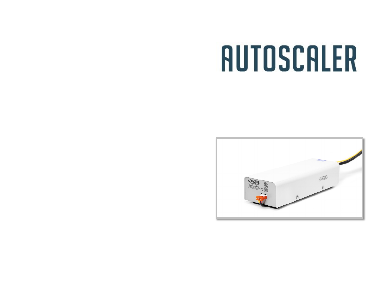
INTRODUCTION
Your South East Instruments AUTOSCALER® Ultrasonic Scaler BUILD-IN
UNIT, is a precision engineered instrument, constructed with the nest
of materials. By taking the following precauons your unit will give you
many years of service.
The AUTOSCALER® BUILD-IN unit is NOT a table top user installaon
product. It must be installed by a qualied technician knowledgeable
in Dental Operatory Air circuitry and Water systems.
1. Do not place unit on or near any source of heat.
2. Unit should be located where a normal amount of air will circulate
freely around the case when in use.
3. The handpiece is very strong but care should be taken NOT TO
PULL with excessive force.

19
Basically, the unit consists of two major components, the Electronic
Generator and the Handpiece Assembly (Water Source is also NECESSARY
but not supplied with this model). The Water Supply is used from the
Dental operatory, and must be applied/congured by a qualied technician.
ELECTRONIC GENERATOR AND WATER SYSTEM
The electronic generator produces the frequency and the power to acvate a
wide variety of interchangeable INSERT TIPS. A Water System/SUPPLY MUST BE
ATTACHED to your unit to provide precise control over the water ow which
serves to wash debris from the work area, and to cool the laminaons of the
insert p. The following is a brief descripon of controls needed for the proper
operaon of your AUTOSCALER®:
The AIR SOURCE (20 PSIG) minimum is required, and (must be
installed by a qualied technician) providing an independent supply of
air to your AUTOSCALER® unit.
POWER CONTROL KNOB: The linear Power Control knob adjusts the
output power to the insert p (must be installed by a qualied technician).
WATER CONTROL (supplied by the dental operatory, and is not part
of the AUTOSCALER® unit) is for adjusng the ow of water to the
handpiece, and insert p. To obtain the NECESSARY water ow of at
least (18cc - 30cc/+/minute) - i.e. a very strong mist, it may require more
than ONE or MORE complete rotaons of the knob in either direcon.
Depending on the water regulator supplied in your operatory the following
applies: HIGHER water ow to the RIGHT, and LOWER water ow to the
LEFT. Some water regulators adjust the opposite (more ow to le and less to
the right). Become familiar with your controls rst before performing any
dental procedures on paents.
HANDPIECE ASSEMBLY
The handpiece assembly is used to accept Cavitron® interchangeable
insert ps. It is connected to the AUTOSCALER® through specially
routed wires in your operatory (INSTALLED BY QUALIFIED TECHNICIAN
ONLY). The open end of the handpiece will accept all Cavitron® brand:
"P", "TFI™", “SLIMLINE™” or “FSI™” style 25,000Hz (25K) inserts. If you
ordered a 30,000Hz (30K) model AUTOSCALER® you must use the
shorter (30K) frequency insert ps.
30K ps measure (Shorter style approx. 6.25 inches long)
25K ps measure (Longer style approx. 7.25 inches long)
*Cavitron®, SLIMLINE™, FSI™, and TFI™ are registered trade marks of Dentsply Sirona
30K
25K
20
(25K) inserts will NOT work in your 30K unit.
(30K) inserts will NOT work in your 25K unit.
Inserts are extremely FRAGILE . If one is dropped, bent, or scratched it
WILL NOT cavitate (i.e. will not funcon) or funcon by operang at a
higher than normal temperature and should be replaced immediately.
Insert ps should be rounely replaced according to insert
manufacturer's recommendaons.
ELECTRICAL REQUIREMENTS
A GROUNDED electrical receptacle is required supplying 120-130
volts 50/60 Hz A.C. If a 3 to 2 prong adapter is used, the ground wire
MUST be connected to the base plate screw. Have an electrician test
your outlet for correct wiring polarity and a safe ground. DO NOT plug
the AUTOSCALER® in a GFI (Ground Fault Interrupt ) outlet.
HANDPIECE—POWER CONTROL POT INSTALLATION
Two 18 gauge wires must be routed between the AUTOSCALER®
console and the handpiece assembly. Thinner wire may result in
poor tuning/operaon or non funcon.
Two 18 gauge wires must be routed between the AUTOSCALER®
unit and the Power Control Pot. A minimum of ½ wa rang @ 5K
ohms is required if substung the power control pot with
another brand/style.
INSTALLATION AND OPERATION
1. The Water Control Knob should be in the HIGH posion. It is
normal for the Knob to turn past the High posion several
rotaons which will increase water ow substanally.
Depending on the water regulator supplied in your operatory the
following applies: HIGHER water ow to the RIGHT and LOWER
water ow to the LEFT. Some water regulators adjust the opposite
(more ow to le and less to the right). Become familiar with your
controls rst before performing any dental procedures on
paents.
2. Your unit is equipped with a AIR SWITCH ACTIVATOR. The air
supply must be aached to the rear of the unit, and a minimum
of ( 20 PSIG ) is necessary to acvate the switch. DO NOT
REMOVE THE INTERNAL AIR RESTRICTOR FITTING. The restrictor
relieves the air input line if accidentally charged from another air

21
source without a purge cycle. The scaler air line will bleed o to
zero pressure protecng the AUTOSCALER®.
3. Plug the power cord into the wall (see electrical requirements).
4. Select an insert. Moisten the rubber O-RING before inserng into
the handpiece. While holding the handpiece, UPRIGHT, place the
insert in the open end of the handpiece, and with a gentle PRESS
and TURN moon, snap the insert in fully. DO NOT force the insert.
5. Manufacturer recommends the use of a disposable handpiece
sleeve/barrier be used over the handpiece assembly. Place the
sleeve/barrier over the handpiece. While holding the sleeve/
barrier in place, puncture the insert through the plasc at the
open end of the handpiece, and snap the insert in fully. Dispose of
sleeve/barrier aer each paent.
6. Due to atmospheric exposure, and exposure to sterilizaon
soluons, the O-RING on the insert p may become swollen,
brile, or crack, and require replacement.
7. Set the POWER KNOB all the way to the LEFT in the LOW posion
8. Hold the handpiece in a VERTICAL upright posion, and step on
the foot switch. Within 10-15 seconds water should come out of
9. Inserts and handpiece will burn in 45-60 seconds in the absence
of water. A (18cc—30cc/+/min) ow is the normal ow range, and
necessary at all mes. NEVER touch the Cavitang/Vibrang end
of the insert p to any esh such as the cheek, tongue, or gums
unless performing special periodontal procedures. This will cause a
FRICTION BURN to the paent. Always keep the insert in moon.
Do not rest the handle or insert on the lips during a procedure.
The insert p should touch primarily the calculus on the tooth
surface, and NOT the enamel of the tooth surface.
10. Allow the air bubbles to escape for about 10-20 seconds. Turn the
POWER KNOB to the RIGHT in the Medium posion, and the
insert p should Cavitate/Vibrate with a strong mist. Turn the
water knob to the right if there is no mist or weak misng.
the open end of the handpiece IF NOT, QUICKLY
turn WATER KNOB clockwise 1-2 rotaons to get
water ow. Some air will escape at the same
me. This step is IMPORTANT because trapped
air will cause HOT SPOTS (usually noted by a
loud screeching sound) which can aect the
performance of the AUTOSCALER® or
permanently damage the handpiece assembly.
22
11. The applicaon of the power knob is for controlling the Output
Power to the insert p in a smooth linear acon. The operator can
select the EXACT power needed for cleaning. Set power knob LOW
(Le Direcon) to MEDIUM (Center) for cooler handpiece/insert
temperature.
12. The high power seng is for applicaons where an excessive
amount of calculus is built up. The Low power seng can be used
for periodontal Subgingival cureage and root planing
procedures. Most scaling should be done only on the LOW to
MEDIUM power seng.
13. If SLIMLINE™, FSI™ or Modied Periodontal inserts are used, set
the POWER Knob in the BLUE shaded area. This power level is
designed to be used with these fragile specialty inserts. Inserts
may give a drip and mist combinaon, this is normal for these
inserts. This is actually preferred by most Periodontal
professionals due to the water drip being ultrasonically acvated
within 0.5mm of the p assisng in killing plaque.
UNIT IS NOW READY FOR USE
SHUT DOWN PROCEDURE
Be sure to shut o Air and Water supply to the scaler when
unaended. The installing service technician will indicate to the
operator which controls perform this acon.
TROUBLESHOOTING
If the unit does not funcon, proceed with the following:
1. Check the plug. Is it all the way in the receptacle?
2. Try another insert. Make sure it is the correct frequency 25K or
30K depending on your model. Each model has a frequency (25K or
30K) label on the cover and the frequency is also indicated on the
serial number plate located on the boom of the device. The most
common mistake when purchasing a new unit is selecng the
wrong frequency insert.
3. If water ow is insucient, check water pressure at the operatory for
minimum of 20 P.S.I. The Insert Water slot could be clogged with
debris. Try another insert.
4. If the handpiece handle or insert operates HOT: REDUCE POWER
LEVEL and INCREASE WATER FLOW. Depending on the water
regulator supplied in your operatory the following applies: HIGHER
water ow to the RIGHT, and LOWER water ow to the LEFT. Some
water regulators adjust the opposite (more ow to le and less to the

23
right). Become familiar with your controls rst before performing any
dental procedures on paents.
5. NEVER touch the Cavitang/Vibrang end of the insert p to any
FLESH such as the cheek, tongue, or gums unless performing special
periodontal procedures. This will cause a fricon burn to the paent.
Always keep the insert in moon. Do not rest the handle or insert on
the lips during a procedure. The insert p should touch PRIMARILY the
calculus on the tooth surface, and NOT the enamel of the tooth
surface.
6. If the AUTOSCALER® stops funconing or is intermient when the
handpiece cord is moved, this means a wire in the handpiece cord is
broken and must be immediately repaired or replaced. DO NOT
connue to press the foot switch as there is a possibility the internal
circuit safety fuse may blow and require replacement by a qualied
technician.
7. If a humming or high pitch sound is noted from the console during
roune use, this is a normal circuit resonance which will change as the
POWER control knob is adjusted up and down, and will not aect the
performance of your AUTOSCALER®.
8. Slimline™ and FSI™ inserts are extremely thin and FRAGILE. During
normal use the water may not mist like standard inserts (i.e. like a
TFI#10 curee p). However, the cleaning acon is just as eecve. It
is recommended the Power knob be set in the LOW posion (Blue
area) to assure best performance.
Call your dealer or customer service at South East Instruments for
further instrucons at (800) 648-9445 to help you with quesons and
what to do next.
SCALING TECHNIQUES
Scaling techniques are at the opon of the professional using this
instrument.
1. Excessive pressure is not necessary with the AUTOSCALER®. Use a
gentle, rapid moon with small overlapping strokes, being certain that
the insert is at a 15 degree angle to the tooth surface.
2. If paent Hypersensivity is noted, you should lighten pressure on the
handpiece, Reduce the Power Level, or move from the sensive tooth
to another, and return to the tooth later. If sensivity persists, switch
to a hand instrument.
24
Front view 25K and 30K
Rear view
Circuit board 20mm-4.0 amp
Fuse Fast Blow
AC power AGC 2.0 amp Fuse
Fast Blow
BRIEF LAYOUT OF THE BUILD-IN STYLE AUTOSCALER®

25
Connect the AC POWER CORD to supply. GROUND conductor MUST BE
Used.
Connect Handpiece leads, and Power Control pot leads according to
drawing FRONT VIEW. There is NO POLARITY for Handpiece leads or
Power Control Pot leads. IT IS SUGGESTED THE 15’ EXTENSION WIRES
(not supplied) CONNECTED TO THE AUTOSCALER® CONSOLE BE
SOLDERED TOGETHER, AND INSULATED WITH A “UL or CSA”
APPROVED SHRINK TUBING Hand twisng and taping of wire
connecons is NOT recommended. It may aect the performance and
safety of the installaon.
When installing the AUTOSCALER® build-in unit, the AIR SOURCE used
to acvate the scaler MUST be independent of all other operatory
equipment, and the supply line pressure must relieve to ZERO PSI aer
each acvaon. The AUTOSCALER® unit may be damaged by acvaon
while other equipment is in use if the air signal is not turned OFF to
the scaler, and line pressure fully relieved when not in use.
The AUTOSCALER® is internally ed from the factory with a pressure
relief valve (restrictor) and must not be removed. This restrictor helps
relieve line pressure aer each acvaon.
IMPORTANT: The AUTOSCALER® unit has been calibrated
ancipang approximately 15’ Fieen feet of 18 GAUGE wire will be
used in the installaon. DO NOT use any wire thinner than 18 GAUGE.
This will change the tuning (i.e. insert will not vibrate properly) of the
AUTOSCALER® and/or not funcon.
26
ULTRASONIC SCALER INSERTS
DIRECTIONS FOR USE FOR OPTIMAL FUNCTION.
Sterilize before each use in accordance with the insert
manufacturer’s instrucons
Federal Law restricts the device to sale by or on the order of a
licensed praconer
3 month warranty
INSERT DEVICE DESCRIPTION
Ultrasonic inserts are accessory inserts designed for use with
magnetostricve scaler units, (see specicaons) that generate a
frequency of either 25KHz or 30KHz. A range of p designs are available to
suit dierent clinical condions. Finger-grips are either plasc or metal
and the water channel is either of internal or external design. These
inserts are designed to be used in magnetostricve ultrasonic scalers only
by professionally trained operators, such as Densts or Dental Hygienists,
to perform general supra and subgingival scaling procedures.
Internal water channel with plasc nger-grip
External water channel with metal nger-grip
Tip Design Applicaon
DF#3 Beaver Tail/Flat
DF#10 Universal Curee
Heavy to moderate supragingival deposits
on buccal and lingual surfaces.
Heavy to moderate supragingival deposits,
light to moderate subgingival deposit on all
surfaces.
DF#100 Periodontal Style Light to moderate supragingival deposits
especially interproximally.
Tip Design Applicaon
DF#10 Universal Curee Heavy to moderate supragingival deposits,
light to moderate subgingival deposit on all
surfaces.
DF#100 Periodontal Style Light to moderate supragingival deposits
especially interproximally.

27
WATER FLOW
An adequate water ow seng, indicated by a small spray or rapid drips,
should be selected for the power seng used to prevent overheang of
the insert p during funcon, and to prevent possible injury.
INSTRUCTIONS FOR USE
Ensure that the insert is suitable for the frequency (25K or 30K) of the
scaler unit. Always sterilize inserts prior to each use in accordance with
the insert manufacturer’s instrucons. Always use a light, smooth, gentle
touch with a well-posioned stable intraoral or extraoral fulcrum. The
lateral surfaces of the insert are normally used for clinical procedures. In
the event that this insert is dropped or damaged or becomes bent, discard
the insert and replace with a new insert. Inserts with high usage, which
exceed the warranty period, should be discarded to avoid in-use breakage
and possible injury.
Inserts should not be used for condensaon of amalgam.
Care must be exercised to avoid iatrogenic results from the use of
ultrasonics in the presence of dental restoraons. Note that the p end or
other sharp aspect of an insert can scratch or otherwise modify the
surface of gold or amalgam restoraons. Thin porcelain veneers and
composite margins can be cracked or crazed by acvated ultrasonic ps.
Normal wear of the p occurs during funcon. When approximately 2 mm
of the p has worn the insert may lose up to 50% eciency, and should be
discarded. Contact with composite restoraons will cause more rapid
arion of ultrasonic inserts.
O-RINGS
Before placing inserts into the handpiece performing the following steps
will increase O-ring life.
1. Fill enre handpiece with water
2. Lubricate O-ring (black or green material) with water
3. Gently twist the insert down into the handpiece unl fully seated
UNIT POWER SETTINGS
1. DP#100, & DF#100 inserts should be used with minimum power
seng only on the unit.
2. DF#10, DF#1000 & DP#10 inserts should be used on low - medium
power seng.
3. DF#3 inserts may be used on medium - high power seng
As a rule the power seng on the unit should always be set at the
minimum and increased only as dictated by clinical requirements.
28
INSERT STERILIZATION
Sterilize inserts before each use in accordance with the insert
manufacturer’s instrucons.
SPECIFICATIONS
These inserts are designed for 25K or 30K magnetostricve scaler
handpieces with:
Internal diameter of 7.3 mm.
Internal length of no less than 125 mm.
INSERTS LIMITED WARRANTY
If, in normal use, any insert is found to be defecve in material or
workmanship within a period of ninety (90) days from the date of
original purchase it will be replaced or the purchase price will be
refunded.
The limited warranty stated herein is the sole and exclusive warranty
to the insert and SEI hereby disclaims any and all other warranes,
expressed or implied, including without limitaon, any statutory
warranes or any warranes of merchantability, tness for use or
tness for any parcular purpose. SEI shall not be responsible for any
inconvenience loss, injury, or direct, indirect, tort, exemplary, punive,
special incidental or consequenal damage arising from the possession
or use of the insert. In no event will SEI's liability exceed the purchase
price of the insert.
Tampering, abuse, misuse, neglect, alteraon, accidental damage,
failure to follow manufacturer's instrucons, improper disinfecon or
sterilizaon procedures, bending, re-grinding or re-shaping, or lack of
reasonable care with respect to the insert will void this warranty. Use
of the insert by anyone other than a licensed dental praconer or
qualied hygienist will void this warranty.
A warranty claim must be accompanied by a dated sales receipt or
other appropriate documentaon showing the date of purchase. In the
event of a warranty claim, it is the responsibility of the user to return
the defecve insert(s) to original purchaser.
This manual suits for next models
1
Table of contents
Popular Media Converter manuals by other brands

Idis
Idis DE-1104 Operation manual

D&H
D&H DH05C manual

Cross Technologies
Cross Technologies 2015-7075 instruction manual

Sierra Video
Sierra Video SV-SM-8 user manual

Comtech EF Data
Comtech EF Data MN/LBC4000.IOM Installation and operation manual

Baumer
Baumer Hubner Berlin HOG 16 + DSL.E Installation and operating instructions


Lika
Lika Posicontrol IF55 LIN CB Series Mounting instructions

CHD Elektroservis
CHD Elektroservis SY2-KBD installation manual

Transition Networks
Transition Networks CGFEB10xx-12x user guide

Linetek
Linetek HD1TO1LR1 user manual

Digital Barriers
Digital Barriers TVI D1000 user manual

Kiloview
Kiloview S2 quick start guide