Autotrol 255-460i User manual

Water Conditioning Control System
Installation, Operation and Maintenance Manual
Series 255 Valve / 460i

2
Table of Contents
Introduction . . . . . . . . . . . . . . . . . . . . . . . . . . . . . . . 2
Series 255/460i Demand Control System
460i Electronic Demand System
Installation . . . . . . . . . . . . . . . . . . . . . . . . . . . . . . . . 5
Location Selection
Water Line Connection
Drain Line Connection
Brine Line Connection
Overflow Line Connection
Splicing Low Voltage Transfer Cord. . . . . . . . . . . . 6
Placing Conditioner Into Operation . . . . . . . . . . . . 6
Programming the 460i . . . . . . . . . . . . . . . . . . . . . . . 7
Manual Regeneration . . . . . . . . . . . . . . . . . . . . . . . 8
Adjustment of Brine Control . . . . . . . . . . . . . . . . . . 9
Removing the 255 Control Module for Servicing 10
Specification. . . . . . . . . . . . . . . . . . . . . . . . . . . . . . 11
Pressure Graphs . . . . . . . . . . . . . . . . . . . . . . . . . . 12
Control Valving Identification . . . . . . . . . . . . . . . . 12
Valve Disc Operation . . . . . . . . . . . . . . . . . . . . . . . 12
Flow Diagrams . . . . . . . . . . . . . . . . . . . . . . . . . . . . 12
Replacement Parts . . . . . . . . . . . . . . . . . . . . . . . . 14
Preventive Maintenance . . . . . . . . . . . . . . . . . . . . 18
Injector Screen and Injector
Water Meter
Troubleshooting . . . . . . . . . . . . . . . . . . . . . . . . . . . 19
Introduction
Series 255/460i Demand Control System
The Series 255/460i demand control system combines
design simplicity with reinforced Noryl* construction to
provide the user with an uncommonly reliable
appliance. The inherent reliability of the system means
a long life of efficient, trouble-free, uninterrupted soft
water luxury.
Should maintenance become necessary, the
Series 255 offers a unique “separation” capability
illustrated in this manual.
Of interest to both the owner and the water
conditioning dealer are the design and operation
benefits detailed below.
Superior Design
•Fewer parts than any control system of
comparable function and most controls of lesser
function.
•Single synchronous electric motor provides all
the power needed to turn the camshaft.
•460i timer utilizes a microprocessor to provide a
time-proven logic analysis to initiate regeneration.
•Electrical wiring is factory assembled. System
cannot be connected incorrectly.
•System indexes manually with or without power
to any one of its service or regeneration positions.
Readout on timer face plate indicates control valve
position.
•No dynamic seals that could cause leakage
through wear or fatigue.
•Control accepts Noryl or brass manifold or
modular bypass valve without modification,
offering complete versatility and easy plumbing for
any installation.
•Brining control valve built into system eliminates
need for an external brine valve.
•Automatic drain flow controller is incorporated
into the system.
Superior Operation
•Direct acting system functions independently of
water pressure. No pistons or diaphragms that
require a minimum water pressure to operate.
•Five-cycle operation provides for downflow
service, upflow backwash, downflow brining,
downflow rinse, downflow purge, or fast rinse. A
sixth position is included for timed refill of the brine
tank.
•Valve discs are held closed by water pressure
and therefore are leak tight. The sealing forces are
increased as the water pressure is increased. Valve
seats are in a vertical position, which is the design
position least vulnerable to plugging.
•System operation cannot get out of phase or
sequence. Control always returns to a fixed service
position after regeneration regardless of where in
the regeneration cycle it was started.
•Bypass water is automatically available during
regeneration.
*Noryl is a trademark of General Electric Company

3
460i Electronic Demand System
The two key components of the 460i electronic
demand system are the microprocessor, a miniature
computer located on the circuit board, and a water
meter located at the valve outlet. The flow of
conditioned water through the meter generates
electrical impulses that tell the computer the amount of
water being used.
Every day, at 2:00 a.m., the past seven days’ water
usage is statistically averaged to anticipate the amount
of water that will be used the next day. The computer
then determines if the water conditioner has enough
remaining capacity to supply the next day’s needs. If
not, the unit will regenerate.
If the water usage pattern changes, the computer
automatically compensates for the change and
regenerates only when needed. This results in higher
operating efficiency and lower salt usage than a
conventional conditioner operating on a fixed
regeneration schedule.
Special Features
Memory Retention
During a power outage, all of the data in the
microprocessor’s memory is stored in a special
electronic chip called NOVRAM, Nonvolatile Random
Access Memory. This data includes the time of day,
water usage amounts, and the number of days since
the last regeneration. When power is restored, the
NOVRAM returns the data to the microprocessor and
operation resumes as if an outage never occurred.
The time of day will be late by the length of the power
outage. Most power outages are less than one minute
induration.Therefore,it maybe monthsor yearsbefore
the time display would require resetting. If an outage of
one or more hours occurs, the time of day should be
reset. No other reprogramming is necessary.
“Reserve” and High Water Usage
“Reserve” refers to the amount of soft water that may
be needed for the next 24 hours. The microprocessor
calculates how much soft water was used and adjusts
thereservecapacityaccordinglyattheendofeachday.
As a result, the reserve is kept at a minimum for
optimum economy. The reserve amount is calculated
by multiplying the average past seven days’ usage
by 1.2. Regeneration decisions are based on the
calculated reserve.
Self-Adjusting Reserve
The 460i is programmed to react to a sudden increase
inwater usage.If aday’s usageismorethandouble the
current average, the computer anticipates that a
second day of high usage is likely to occur. The high
usage amount will be used as the reserve when the
460i performs its regeneration computation.
Low or No Water Usage
The 460i is programmed to recognize a day of very little
or no water usage as an abnormality. It will not use data
from such a day to compute the average usage. For
example, if the family is on vacation for a week, the
prior average will be maintained. When household
activity resumes, the 460i will operate as if the vacation
had not occurred.
Design Reliability
Solid-state electronics assure many years of
trouble-free performance. The metering system has
only one moving part: the rotating turbine that
measures water usage and generates electrical pulses
that are continually counted by the microprocessor to
determine the need to regenerate.
Time Display
The correct time will continually appear in the time
display during normal conditioning operation. To
change the hour display, press the TIME SET BUTTON
until the present hour appears. The PM light will be on
when the time is between 12:00 noon and midnight.
The light is off during the AM hours.
Flow Indicator
The water flow indicator on the time display flashes
whenever conditioned water is flowing through the
valve. This allows an easy determination of proper
meter operation.
Hardness and Capacity Settings
Once the hardness and capacity settings have been
set, the information cannot be lost due to a power
outage; reprogramming is not necessary.
Guest Cycle
An extra regeneration can be achieved at any time by
depressing the pointer knob. It will take a few minutes
for the regeneration to start. The unit will return to
servicein twohours.This featureisbeneficial whenyou
expect to use more than the normal amount of water,
for example: guest visits, extra heavy laundry days, etc.
Programmable Calendar Override
The 460i controller has a unique feature that allows a
calendar override of 1 to 15 days. This override will
initiate a regeneration at the programmed interval if the
water usage has not been enough to initiate
regeneration.
4
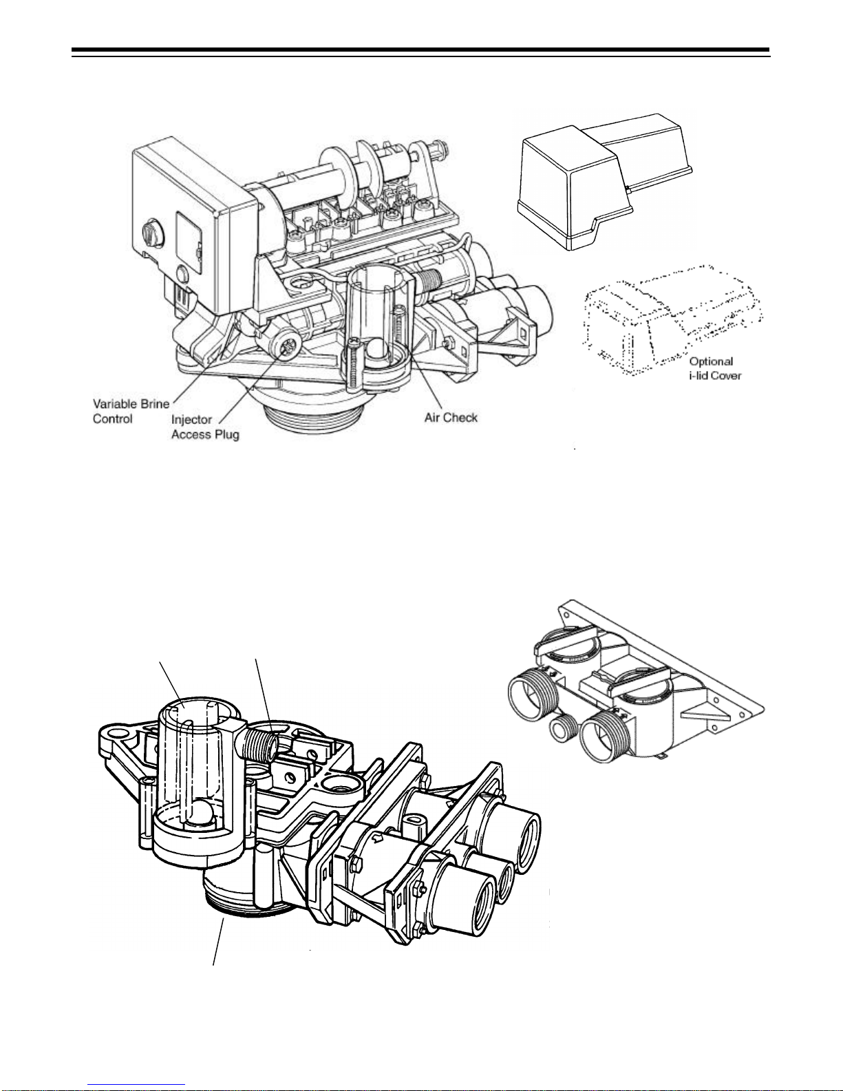
Control Module
Figure 1
Tank Adapter Module
Figure 2
Standard L-Lid
Cover
Brine Line Fitting Connection 1/4-inch NPT
Air Check
Tank Thread 2-1/2-inch - 8 Male
Inlet Connection 3/4-inch or
Drain Connection 3/8-inch or
Outlet Connection 3/4-inch or 1-inch NPT or BSPT
Optional Bypass
1/2-inch NPT or BSPT
1-inch NPT or BSPT

5
Installation
All plumbing must conform to local codes.
Inspect unit carefully for carrier shortage or shipping
damage.
Location Selection
1. Thedistancebetweentheunitandadrainshouldbe
as short as possible.
2. If it is likely that supplementary water treating
equipment will be required, make certain adequate
additional space is available.
3. Since salt must be added periodically to the brine
tank, the location should be easily accessible.
4. Do not install any unit closer to a water heater than
a total run of 10 feet (3 m) of piping between the
outlet of the conditioner and the inlet to the heater.
Water heaters can sometimes overheat to the
extent they will transmit heat back down the cold
pipe into the unit control valve.
Hot water can severely damage the conditioner. A
10-foot (3-m) total pipe run, including bends,
elbows, etc., is a reasonable distance to help
prevent this possibility. A positive way to prevent
hot water from flowing from heat source to the
conditioner, in the event of a negative pressure
situation,isto installa checkvalve inthe softwater
piping from the conditioner. If a check valve is
installed, make certain the water heating unit is
equipped with a properly rated temperature and
pressure safety relief valve. Also, be certain that
local codes are not violated.
5. Do not locate unit where it or its connections
(including the drain and overflow lines) will ever be
subjected to room temperatures under 34oF (1oC)
or over 120oF (49oC).
6. Do not install unit near acid or acid fumes.
Water Line Connection
A bypass valve system must be installed since there
will be occasions when the water conditioner must be
bypassed for hard water or for servicing.
The most common bypass systems are the Autotrol®
Series 256 bypass valve (Figure3) and plumbed-in
globe valves (Figure4). Though both are similar in
function, the 256 Autotrol bypass offers simplicity and
ease of operation.
Figure 3– Autotrol Series 256 Bypass Valve
Figure 4– Typical Globe Valve Bypass System
Drain Line Connection
1. Ideally located, the unit will be above, and not more
than 20 feet (6.1 m) from the drain. For such
installations, using an appropriate adapter fitting
(not supplied), connect 1/2-inch (1.3-cm) plastic
tubing to the drain connection located on the
control.
2. If the unit is located more than 20 feet (6.1 m) from
drain, use 3/4-inch (1.9-cm) tubing for runs up to
40 feet (12.2 m).
3. If the unit is located where the drain line must be
elevated, you may elevate the line up to 6 feet
(1.8 m) providing the run does not exceed 15 feet
(4.6m) andwaterpressure atconditioneris notless
than 40 psi (2.3 bar). You may elevate an additional
2 feet (61 cm) for each additional 10 psi (0.69 bar).
4. Where the drain line is elevated but empties into a
drain below the level of the control valve, form a
7-inch (18-cm) loop at the far end of the line so that
the bottom of the loop is level with the drain
connection. This will provide an adequate siphon
trap.
5. Where the drain empties into an overhead sewer
line, a sink-type trap must be used.
Water
Conditioner Water
Conditioner
Not in Bypass In Bypass
6
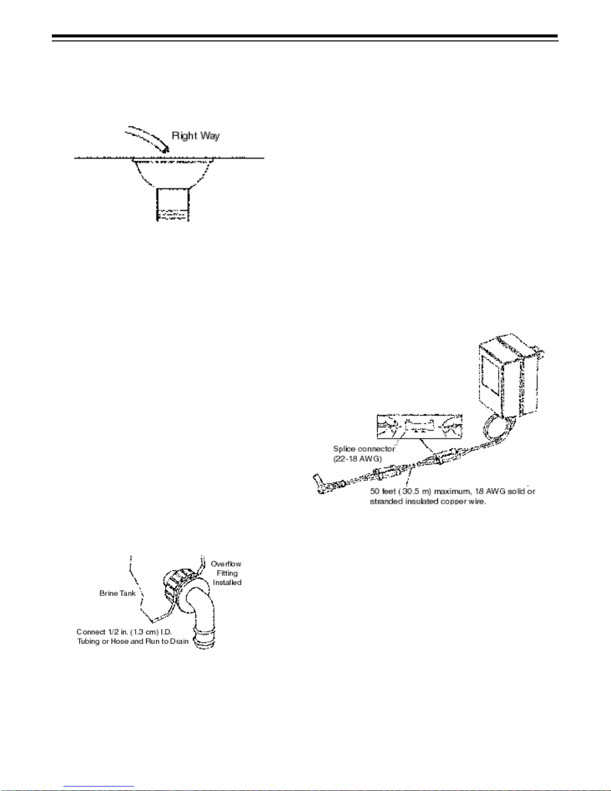
Important: Never connect drain line into a drain, sewer
line or trap. Always allow an air gap between the drain
line and the wastewater to prevent the possibility of
sewage being back-siphoned into conditioner.
Figure 5
Note: Standard commercial practices have been
expressed here. Local codes may require changes to
these suggestions.
Brine Line Connection
Itwillbe necessaryto installthe brinetube andconnect
the line to a fitting installed on the air check.
Be sure all fittings and connections are tight so that
premature checking does not take place. Premature
checking is when the ball in the air check falls to the
bottom before all brine is drawn out of the brine tank.
See Placing Conditioner into Service section.
Overflow Line Connection
To connect overflow, locate the hole on the side of the
brine tank. Insert overflow fitting (not supplied) into tank
and tighten with plastic thumb nut and gasket as
shown(Figure6).Attachlengthof1/2-inch(1.3-cm)I.D.
tubing (not supplied) to fitting and run to drain. Do not
elevate overflow line higher than 3 inches (7.6 cm)
below bottom of overflow fitting.
Figure 6
Electrical Connection
12VAC:
The power supply transformer should have a minimum
rating of 3 volt-amps. Connect the plug of the
transformer secondary cable to the mating socket on
the bottom of the controller.
Be certain the transformer is plugged into a
source that is not controlled by a wall switch and
cannot be accidentally turned off.
Splicing the Low Voltage
Transformer Cord
If it is necessary to extend the length of the transformer
cord, an optional 15-foot (4.6-m) extension cord is
available (P/N 1000907), or the cord may be spliced as
follows:
1. Strip insulation from wire 5/16 inch (.8 cm) from wire
end.
2. Insert stripped wire into barrel of connector and
crimp. For best results, crimp twice per wire as
shown in Figure7.
Splice connectors or extension wire is not supplied.
They are available at hardware or electrical stores.
Figure 7
Placing Conditioner into
Operation
After all previous steps have been completed, the unit
isreadytobeplacedintooperation.Followthesesteps
carefully:
1. Remove control valve cover (Figure 14).
Note: The following steps will require turning the
pointer knob (Figure9) to various positions. Insert a
wide-blade screwdriver into arrow slot in pointer
knob and press in firmly. With knob held in, rotate
COUNTERCLOCKWISE only until arrow or knob
points to desired position. (Rotation is made much
easier if you grasp the camshaft with your free hand
and turn it at the same time.) Then permit knob to
spring back out.
2. Insert screwdriver into slot in pointer knob
(Figure9). Press in and rotate knob

7
COUNTERCLOCKWISE untilarrow pointsdirectly
to the word BACKWASH.
3. Fill resin tank with water.
A. With water supply off, place the bypass valve(s)
into the “not in bypass” position.
B. Open water supply valve very slowly to
approximately the 1/4 open position.
Important: If opened too rapidly or too far, resin may
be lost. In this position, you should hear air escaping
slowly from the drain line.
C. When all of the air has been purged from the
tank and clear water begins to flow steadily
from the drain, close main supply valve.
D. With the water supply off, let the unit stand for
aboutfive minutes.This willallow alltrappedair
to escape from the tank.
E. Proceed to step 4.
4. Add water to brine tank (initial fill). With a bucket or
hose, add approximately four gallons (15 liters) of
water to brine tank. If the tank has a salt platform
above the bottom of the tank, add water until the
level is approximately 1 inch (25 mm) above the
platform.
Figure 8
5. Put into operation.
A. Open water supply valve slowly to full open
position.
B. Carefully advance pointer knob
COUNTERCLOCKWISE to center of FAST
RINSE/REFILL position and hold there until air
check (Figure1) fills with water and water starts
to flow through brine line into brine tank. Do not
run for more than two minutes.
C. AdvancepointerknobCOUNTERCLOCKWISE
until arrow points to the center of the BRINE/
SLOW RINSE position.
D. With the conditioner in this position, check to
see if water is being drawn from the brine tank.
The water level in the brine tank will recede very
slowly. Observe for at least three minutes. If the
water level does not recede or goes up, or if air
enters the transparent air check chamber and
the ball falls and seats, reference
Troubleshooting section.
E. AdvancepointerknobCOUNTERCLOCKWISE
to CONDITIONED WATER.
F. Run water from a nearby faucet until the water
is clear and soft.
Programming the 460i
Plug the wall mount transformer into a functioning
electrical outlet that is not controlled by a switch. Plug
the transformer plug into the transformer plug
receptacle on the timer.
Note: If the included transformer cord is not long
enough, a 15-foot (4.6-m) extension is available. See
Splicing the Low Voltage Transformer Cord section
of this manual.
Open the access door by pushing the raised tab on the
door toward the left while pulling the tab out (Figure9).
Figure 9
Time of Day Setting
With the jumper on the set of pins next to the word
TIME (Figure 10), set the time of day to the closest hour
by pressing the black TIME SET button. PM hours are
indicatedbyalightnexttothelettersPMon thedisplay
window.
255/460i shown with optional i-lid cover (PN 1000062)
PM Indicator
Water Flow Indicator Hour Time Display
Access Door
Pointer Knob
Time Set Button Transformer Plug
Receptacle
Jumper
Spare
Raised
Tab
Jumper

8
Note: The use of a small needle nose pliers or tweezers
will aid in moving the jumper.
Note: The unit is factory set to regenerate at 2:00 a.m.
If you prefer to have the unit regenerate at an earlier or
later time, simply set the current time of day
accordingly. To have the unit regenerate at 4:00 a.m.,
two hours later, set the clock two hours earlier than the
actual current time.
Hardness Setting
Move the jumper to the set of pins next to the word
HARDNESS (Figure 11). Press the black TIME SET
button until the correct hardness is displayed. The
hardness range is from 1 to 99 grains per gallon.
To change water hardness stated in parts per million
(PPM) to grains per gallon (GPG) use this formula:
Parts per Million = Grains per Gallon
17.1
Capacity Setting
Move the jumper to the set of pins next to the word
CAPACITY (Figure 12). Press the black TIME SET
buttonuntil thecorrect capacityvalue isdisplayed.The
capacity range is 1 to 99 kilograins. Refer to the
Suggested Salt Dial Settings table.
Return the jumper to the top set of pins next to the
word TIME and replace the access door. The next three
sets of pins are used for factory testing and are not
used in normal operation. The jumper must NOT be left
on any pins other than the top pair next to the word
TIME. Otherwise, the unit may not function.
Note: A spare jumper is located on the bottom set of
pins.
In the event that the hardness or capacity setting must
be changed, simply follow the appropriate steps
described above.
Calendar Override Setting
1. Disconnect power.
2. Place jumper on Pin A and reconnect power.
3. Movejumper toPinB. Azerowill appear,indicating
zero days of calendar override. All 460i controllers
are preprogrammed in this manner at the
manufacturer.
4. Depress the black TIME SET button. The numbers
will roll from “0” to “15.” Release the switch at the
desired number of days for the calendar override.
For example, releasing the switch at “10” would
program a 10-day calendar override.
5. Disconnect power.
6. Place jumper back on TIME and reconnect power.
7. The calendar override program is maintained
during power outages by the NOVRAM circuitry.
8. To remove the calendar override, follow the same
steps above and program back to “0.”
Manual Regeneration
Electricity is used only to run the timer and to rotate the
camshaft. All other functions are operated by water
pressure. Therefore, in the event of a power outage, all
the regeneration positions may be dialed manually by
depressing the pointer knob with a straight blade
screwdriver and turning COUNTERCLOCKWISE.
Manual time cycle:
•Backwash–14 minutes
•Brine/Slow Rinse–52 minutes
•Brine Refill–10 minutes
•Fast Rinse/Refill–6 minutes.
Do not exceed 10 minutes for the refill cycle as this will
cause excessive salt usage during the next
regenerationandpossiblya saltresidueinthesoftened
water.
DO NOT advance the pointer knob directly to the
conditioned water position (6 o’clock) after a manual
regeneration or when servicing the conditioner.
Advance it to just past the purge position,
approximately 7 o’clock. The timer will then advance
itself to the conditioned water position where the
internal switch will turn the motor off. The internal
switch will not be operated and the motor will continue
to run if advanced directly to the conditioned water
position.
If power fails during a conditioner regeneration, the
cycle will be completed normally when the power is
restored.
Figure 10 Figure 11 Figure 12
9
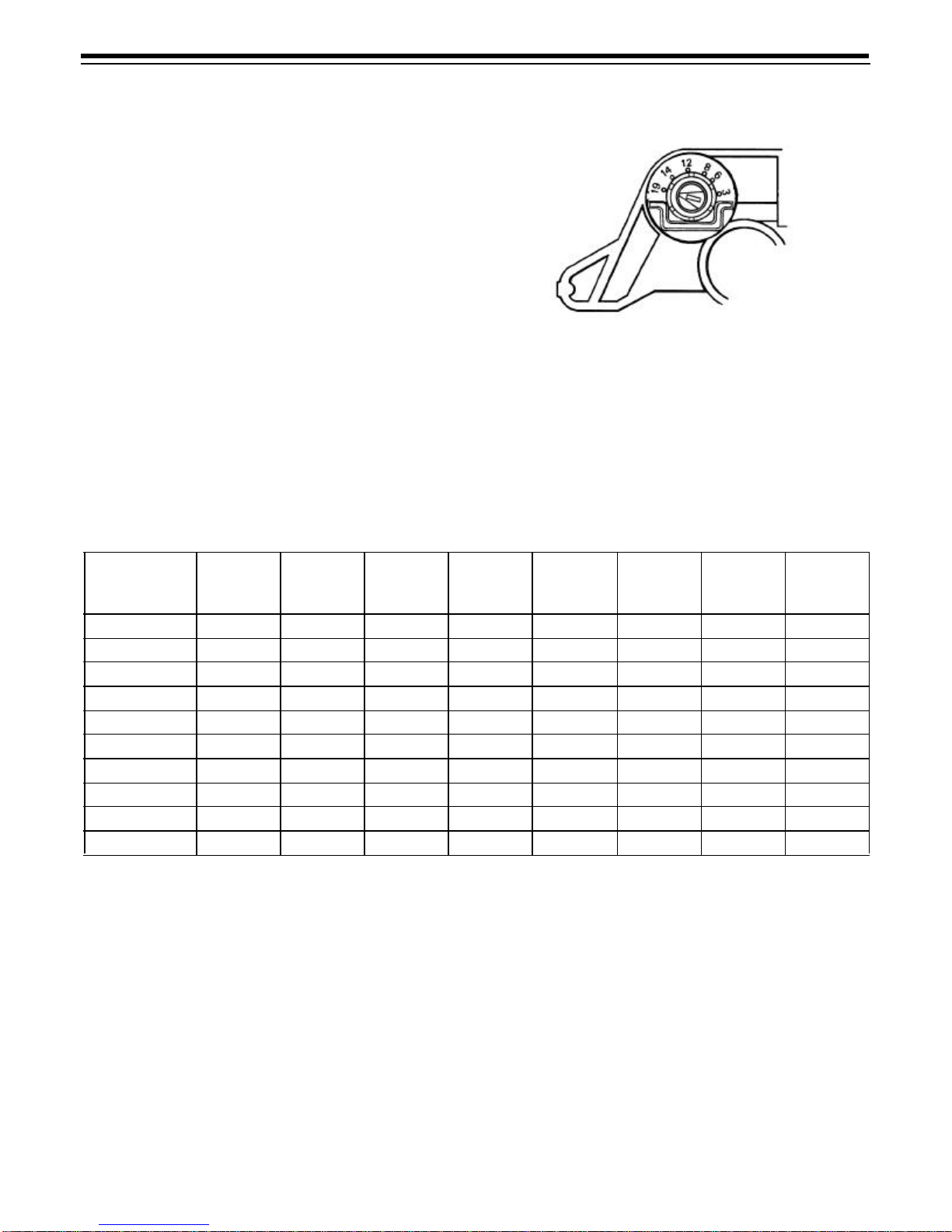
Adjustment of Brine Control
The amount of salt placed into the regenerant storage
tank has nothing to do with the amount of salt used
during the regeneration cycle. Water will dissolve and
absorb salt only until it becomes saturated. A given
amount of brine (salt-saturated water) contains a
specific amount of salt.
The salt dial controls the amount of brine used during
the regeneration cycle, e.g., when set at 15 lbs. (6.8 kg)
the amount of brine the conditioner will use for each
cycle will contain 15 lbs. (6.8 kg) of salt. Never let the
amountof saltin thebrine tankbelessthanthe amount
required for the next regeneration.
Refer to the Suggested Salt Dial Settings Table
(Table 1) for proper salt settings. To set the salt dial,
insert a screwdriver into the slot (Figure 13) and move
the pointer to the proper setting.
Note: To convert the salt settings from English to
metric, divide by 2.2 (e.g., 12 pounds ÷ 2.2 = 5.5 kg. of
salt).
Figure 13
*This setting requires the use of “XS” (extra salt) cam and doubles the amount of the setting.
Table 1 – Suggested Salt Dial Settings (Pounds of Salt) For Various Size Softeners
Capacity
Setting
(Kilograins) 0.5 Ft30.75 Ft31.0 Ft31.25 Ft31.5 Ft31.75 Ft32.0 Ft32.5 Ft3
12 4.5 ———————
16 9.0 5.5 ——————
20 —8.5 6.0 ————
24 —14.0 8.5 7.0 ————
30 — — 15.0 11.0 9.0 ———
32 — — 18.5 12.5 10.0 9.0 — —
35 — — — 16.0 12.0 10.0 9.0 —
40 — — — 11.5* 17.0 14.0 12.0 —
48 — — — — 14.0* 10.5* 17.0 13.0
60 ——————15.0* 10.5*

10
Removing the Series 255 Control Module for Servicing
1. Unplug the transformer cable from the control.
2. Shut off water supply or put bypass valve(s) into
bypass position.
3. Remove cover (Figure14) and with a screwdriver,
relieve tank pressure by pushing open valve
number 6 (at rear) (Figure15).
Figure 14
Figure 15
4. Remove screw in locking bar (Figure 16).
Figure 16
5. Applydownward handpressureoncontroland pull
locking bar out (Figure17).
Figure 17
6. Using a rocking motion, lift control from the tank
adapter (Figure18). If O-rings come off with the
control put them back into tank adapter sockets.
Lubricate O-rings with silicone lubricant.
Figure 18
7. To replace control module, reverse above
procedure.
Outlet Drain Inlet
11
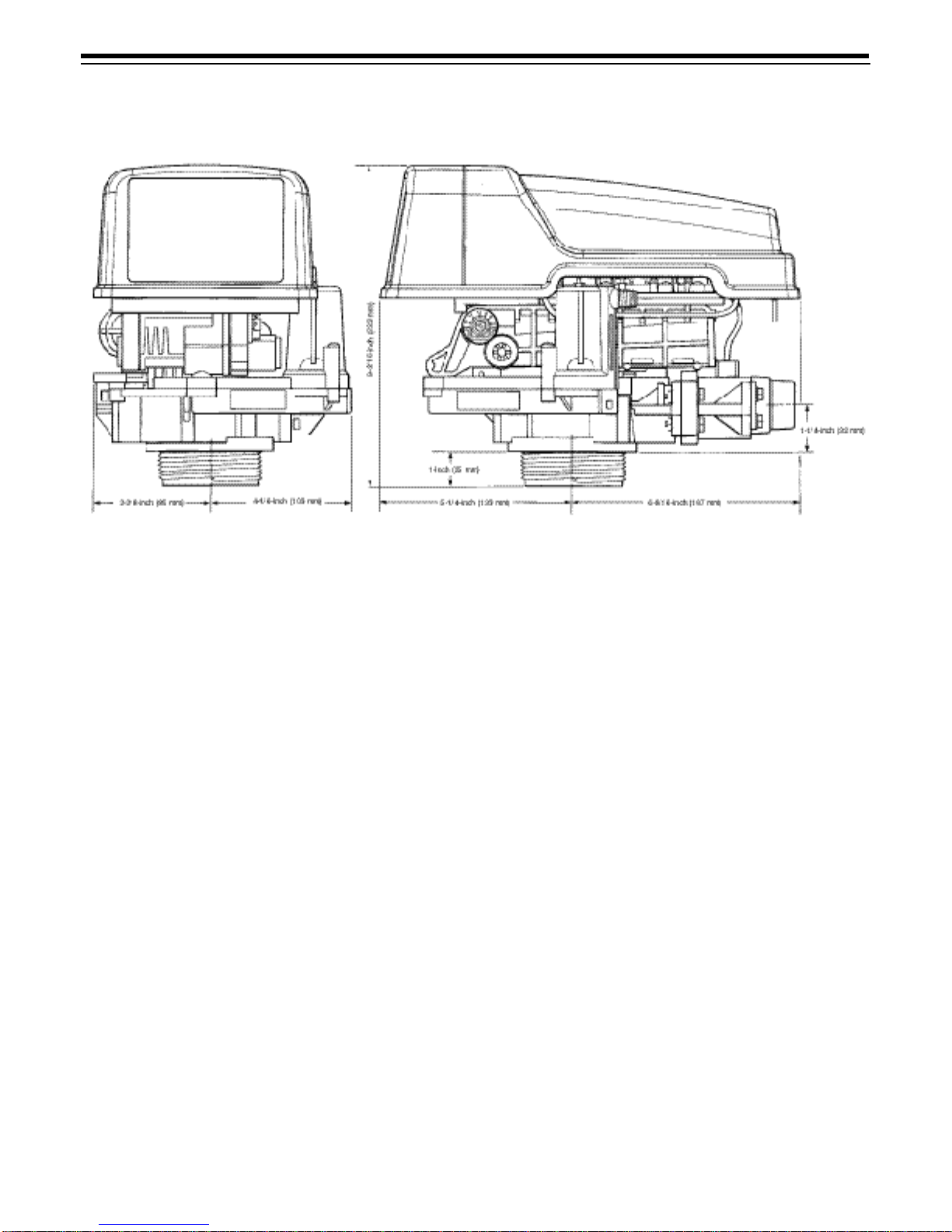
Specifications
Hydrostatic Test Pressure...............................................................................................................................300 psi (20.69 bar)
Working Pressure................................................................................................................................20-127 psi (1.38-8.76 bar)
Standard 12 Volt Transformer Input Electrical Rating.................................................................................................115V 60Hz
Optional 12 Volt Transformer Input Electrical Rating........................................................................... 115V 50 Hz, 230V 50 Hz,
230V 60 HZ, 100V 60Hz, 100V 50 HZ
Transformer Cord.........................................................................................................................................120 inch (1.5m) long
Pressure Tank Thread .......................................................................................................................................2 1/2 inch 8 male
Brine Line Thread............................................................................................................................................1/4 inch NPT male
Distributor Tube Diameter Required ............................................................................................................13/16 OD (20.6 mm)
Distributor Tube Length ............................................................................ 1 1/4 inch (31.8 mm) higher than top of mineral tank
Standard Manifold Connection.............................................................................3/4-inch NPT inlet-outlet, 3/8-inch NPT drain
Optional Manifold Connection.................................................................................1-inch NPT inlet-outlet, 1/2-inch NPT drain
3/4-inch BSPT inlet-outlet, 3/8-inch BSPT drain
1-inch BSPT inlet-outlet, 1/2-inch BSPT drain
Optional Bypass Valve...............................3/4-inch (19.1 mm) or 1-inch (25.4 mm) copper tailpiece, 1/2-inch NPT male drain
Control Module, Tank Adapter, Optional Bypass Valve .................................................................................Reinforced NORYL
Inlet-Outlet Manifold .........................................................................................................................Brass or reinforced NORYL
Rubber Goods ....................................................................................................................Compounded for cold water service
Brine Refill Control...........................................................1 to 10 lbs (0.45 to 4.5 kg) of salt or 3 to 19 lbs (1.3 to 8.6 kg) of salt
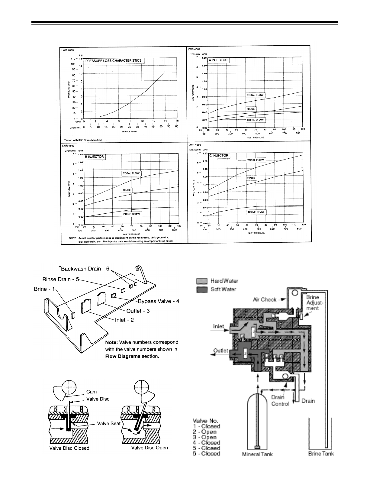
Injector Size “A” White..............................................Nozzle .042 inch (1.1 mm) Diameter, Throat .089 inch (2.3 mm) Diameter
Injector Size “B” Blue ...............................................Nozzle .052 inch (1.3 mm) Diameter, Throat .099 inch (2.5 mm) Diameter
Injector Size “C” Red................................................Nozzle .059 inch (1.5 mm) Diameter, Throat .099 inch (2.5 mm) Diameter
Backwash Controllers Available for ...............................................................................................6, 7, 8, 9, 10, 12, 13, 14 inch
(15.2, 17.8, 20.3, 22.9, 25.4, 30.5, 33.0, 35.6 cm) diameter mineral tanks.
All are sized to flow 4.5 gpm/sq ft (183 L/m/m2) of bed area.
Shown with optional i-lid cover PN 1000062.
12
Pressure Graphs
Control Valving Identifications
Valve Disc Operation
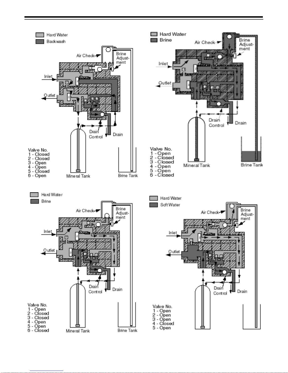
Flow Diagrams
1–Conditioned Water Position
bar
bar
bar
Use with #8 or Larger
BackwashControl
Use with #10 or Larger
Backwash Control
bar
13
2–Backwash Position
4–Slow Rinse Position
3–Brining Position
5–Brine Refill and Purge Position
14
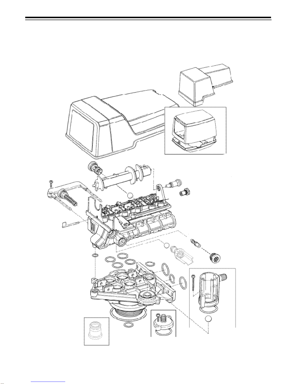
Replacement Parts
Valve Body and Tank Adapter Module
3
22
20
6
15 14
2
18
16
8
9
19
57
7
1
23 23 23
24
24
24
11
25
17
10
12
13
21
4

15
Valve Body and Tank Adapter Module
Code Part No. Description Qty.
11000232 Valve Assembly, w/o Flow
Controls 1
21031950 Camshaft, Standard, One-
Piece 1
31000062 Valve Cover, Black with
transparent window 1
4Brine Refill Flow Control
Assembly: 1
1034261 1 to 10 lbs Salt
1034263 3 to 19 lbs Salt
51000226 Screen/Cap Assembly with
O-Ring 1
6Backwash Control Assembly
with O-Rings: 1
1034162 No. 6 for 6 in Diameter Tank
1000209 No. 7 for 7 in Diameter Tank
1000210 No. 8 for 8 in Diameter Tank
1000211 No. 9 for 9 in Diameter Tank
1000212 No. 10 for 10 in Diameter Tank
1000213 No. 12 for 12 in Diameter Tank
1000214 No. 13 for 13 in Diameter Tank
1000215 No. 14 for 14 in Diameter Tank
71030502 Ball, Flow Control 1
8Injector Assembly with
O-Rings: 1
1032970 “A” Injector - White
1032971 “B” Injector - Blue
1032972 “C” Injector - Red
Code Part No. Description Qty.
9Injector Cap with O-Ring: 1
1000217 “A” Cap
1000218 “B” Cap
1000219 “C” Cap
10 1033784 Tank Adapter Assembly 1
11 1032416 Air Check Assembly 1
12 1010429 O-RingBN 1
13 1010428 O-RingEP 1
14 1031402 Locking Bar: English Language 1
15 1006093 Screw, No. 8 x 9/16 inch 1
16 1001580 Spring, Valve Disc Kits: 9
17 1033066 New to Old Aircheck Adapter
Kit 1
18 1000297 Extended Bearing, Camshaft 1
19 1031391 Pin, Locking, Timer, Black 1
20 Covers, High Style:
1041087 Beige/Tan
1041088 Black/White
1041091 Beige/Black
21 1030501 Bearing, Camshaft for use with
Cover (Code 22)
22 1032565 Cover, L-lid
23 1001404 O-Ring Group: Tank Adapter
24 1040459 O-Ring Group: Piping Boss
25 1041010 13/16-inch Riser Insert
(optional)
*1000250 Valve Disc Replacement
* Not shown
16
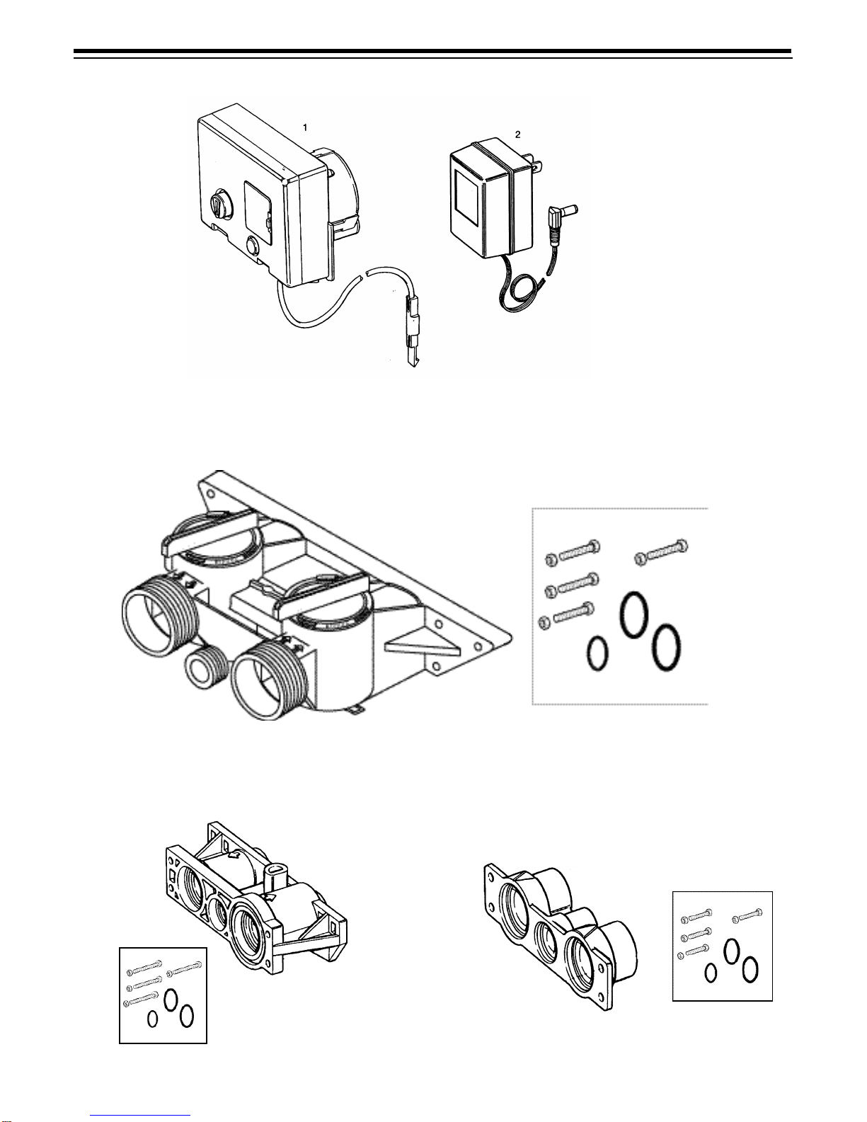
460i Timer
Bypass Valve
Meter Adapter Piping Boss
Note: Do not use pipe joint compound when threading
pipe into the Noryl piping boss. Use only Teflon*pipe tape.
Do not overtighten pipe into Noryl piping boss.
*Teflon is a registered trademark of E.I. Dupont de Nemours and Company, Inc.
1
2
1
2
1
2

17
460i Timer
Code Part No. Description Qty.
1460i Timer 1
2Transformer 1
1000810 Japanese
1000811 North American
1000812 Australian
1000813 British
1000814 European
*1000907 Transformer Extension Cord 1
15 foot (4.6 m)
Bypass Valve
Code Part No. Description Qty.
11040769 Bypass Body Assembly 1
21040524 Install Kit 1
*Tube Adapter Kits
1001606 3/4-inch Copper Tube Adapter Kit
1001670 1-inch Copper Tube Adapter Kit
1001608 22-mm Copper Tube Adapter Kit
1001609 28-mm Copper Tube Adapter Kit
1001613 3/4-inch CPVC Tube Adapter Kit
1001614 1-inch CPVC Tube Adapter Kit
1001615 25-mm CPVC Tube Adapter Kit
1001769 3/4-inch NPT Plastic Pipe Adapter Kit
1001603 1-inch NPT Plastic Pipe Adapter Kit
1001604 3/4-inch BSPT Plastic Pipe Adapter Kit
1001605 1-inch BSPT Plastic Pipe Adapter Kit
1001611 3/4-inch BSPT Brass Pipe Adapter Kit
1001610 1-inch NPT Brass Pipe Adapter Kit
1001612 1-inch BSPT Brass Pipe Adapter Kit
Piping Boss
Code Part No. Description Qty.
1Kit Piping Boss 1
(Includes Hardware):
1040277 3/4-inch NPT, Brass
1040278 1-inch NPT, Brass
1040281 3/4-inch BSPT, Brass
1040282 1-inch BSPT, Brass
1040279 3/4-inch NPT, Noryl
1040280 1-inch NPT, Noryl
1040283 3/4-inch BSPT, Noryl
1040284 1-inch BSPT, Noryl
21040339 Piping Boss Install Kit 1
Meter Adapter
Code Part No. Description Qty.
11032350 Kit, Meter Adapter 1
21032351 Meter Install Kit 1
* Not Shown

18
Preventive Maintenance
Inspect and clean brine tank and screen filter on end of
brine pickup tube once a year or when sediment
appears in the bottom of the brine tank.
Injector Screen and Injector
The injector is the component which creates the
vacuum necessary to draw the brine into the water
conditioner.Cleanthe injectorand injectorscreen once
a year in order to maintain proper water conditioning.
Somelocationsmay requiremore frequentinjector and
screen servicing. Refer to Figure 19 and complete the
following steps to clean the injector screen and injector.
1. Unplug the wall mount transformer.
2. Shut off water supply or put bypass valve(s) into
bypass position and remove the rear cover.
3. Relieve system pressure by opening valve
number 6 (at rear) with a screwdriver (Figure 15).
4. Using a screwdriver, unscrew and remove the
injector screen and the injector cap.
5. Clean screen with a fine brush. Flush with water
until clean.
6. Usinganeedle-nose pliers,pull theinjector straight
out.
7. Squirt water into the injector screen recess of the
valve body to flush debris out.
8. Clean and flush injector.
9. Lubricate the O-rings on the injector, injector cap,
and injector screen with silicone lubricant and
reinstall.
Important: Do not overtighten the plastic cap. Seat the
cap lightly into position. Overtightening may cause
breakage of the plastic cap that may not be
immediately evident.
10. Reinstall cover, reconnect electric power, and reset
the time of day.
11. Slowly open the water supply valve or return the
bypass valve(s) to the “not in bypass” position.
Figure 19
Water Meter
In rare instances, the turbine wheel of the water meter
may collect small particles of oxidized iron, eventually
preventing the wheel from turning. The turbine wheel
may be serviced as follows (Figure 20):
1. Shut off the water supply or put bypass valve(s) into
bypass position.
2. Relieve system pressure by opening valve
number 6 (at rear) with a screwdriver (Figure 15).
3. Loosen and remove the fasteners that hold the
meter adapter to the tank adapter and the
fasteners that hold the piping boss or bypass valve
to the meter adapter.
4. Remove the meter adapter, being careful not to
misplace any of the O-rings.
5. Using a needle-nose pliers, grasp one of the four
vanesof thegland and,pulling straightout,remove
the gland from the adapter.
6. Carefully remove the turbine wheel from the
housing. Using a toothbrush, lightly scrub the iron
off the magnet. Iron buildup on the wheel surfaces
may be removed by soaking the wheel in a mild
sodiumhydrosulfite(e.g., RoVer*)solution fora few
minutes, then flushing thoroughly with water.
7. Carefully reinstall the turbine wheel into the
adapter, being certain that the shaft of the wheel
seats into the bearing of the adapter and that the
“dimple” on the wheel faces you.
8. Carefully reinstall the gland into the adapter, being
certain that the shaft of the wheel seats into the
bearing of the gland; press the gland all the way in,
being sure the wheel rotates freely.
9. Reinstall the meter adapter, O-rings, piping boss,
or bypass valve, tighten all fasteners and re-
establish the water supply to the system.
10. Checkforproperwatermeteroperationbyopening
a downstream faucet and observing the water flow
indicator light on the 460i display.
*RoVer is a trademark of Hach Chemical Company.
Figure 20
Screen
Brine Control
Injector

19
Troubleshooting
Your water conditioning system is designed and
manufactured for efficient, low maintenance service.
However, if problems occur, this section provides a list
of possible causes and solutions. You can solve some
problems yourself, such as low salt in the salt storage
tank or a blown household fuse. However, some
problems require installer or dealer assistance.
Important: Service procedures that require the water
pressure to be removed from the system are marked
with a !.To removewater pressurefrom thesystem,put
the bypass valve or three-valve bypass into the bypass
position and open the backwash drain valve (the sixth
valve back from the control) with a screwdriver. Restore
system water pressure when the service work is
complete.
Problem Possible Cause Solution
1. Clock does not display
time of day. a. Transformer cord unplugged.
b. No electric power at outlet.
c. Defective transformer.
d. Defective circuit board.
a. Connect power.
b. Repair outlet or use working outlet.
c. Replace transformer.
d. Replace timer.
2. Clock does not display
correct time of day. a. Outlet operated by switch.
b. Incorrect voltage or frequency (Hz).
c. Power outages.
a. Use outlet not controlled by switch.
b. Replace timer with one of correct
voltage and frequency (Hz).
c. Reset clock.
3. Time display continues
to advance. a. Defective time set switch. a. Replace timer.
4. Time display shows
something other than
time of day.
a. Electrical interference.
b. Defective circuit board.
a. Disconnect power to unit. Restore
power and reset time of day display.
b. Replace timer.
5. No water flow display
when water is flowing. a. Bypass valve in bypass.
b. Meter probe disconnected or not
fully connected to meter housing.
c. Restricted meter turbine rotation
due to foreign material in meter !
d. Defective meter probe.
e. Defective circuit board.
a. Shift bypass valve to not-in-bypass
position.
b. Fully insert probe into meter housing.
c. Remove meter housing, free up turbine
and flush with clean water. Turbine
should spin freely. If not, replace meter.
d. Replace timer.
e. Replace timer.
6. Control regenerates at
wrong time of day. a. Power outages.
b. Clock set incorrectly. a. Reset clock to correct time of day.
b. Reset clock to correct time of day.
7. Timer stalled in
regeneration cycle. a. Motor dead.
b. Motor runs backward.
c. No electric power at outlet.
d. Broken gear.
e. Defective switch.
f. Air leak in brine connections.
g. Binding of camshaft.
h. Water pressure greater than 25 psi
(1.72 bar) during regeneration !
i. Defective circuit board.
a. Replace timer.
b. Replace timer.
c. Repair outlet or use working outlet.
d. Replace timer.
e. Replace timer.
f. Check all junction points and make
appropriate corrections.
g. Remove foreign object obstruction from
valve discs or camshaft.
h. Install pressure regulator.
i. Replace timer.
8. Continuous
regeneration. Camshaft
does not stop at the end
of regeneration.
a. Broken switch actuator on gear.
b. Defective switch. a. Replace timer.
b. Replace timer.

20
9. Control will not
regenerateautomatically
or when button is
pressed.
a. Electric cord or transformer
unplugged.
b. No electric power at outlet.
c. Defective motor.
d. Broken gear.
e. Binding in gear train.
f. Defective switch.
a. Connect power.
b. Repair outlet or use working outlet.
c. Replace timer.
d. Replace timer.
e. Replace timer.
f. Replace timer.
10. Control will not
regenerateautomatically
but will regenerate when
button is pressed.
a. If water flow display is not operative,
refer to Item 5.
b. Defective circuit board.
c. Incorrect hardness and capacity
settings.
a. Same as Item 5.
b. Replace timer.
c. Setto correct values.See Programming
section.
11. Run out of soft water
between regenerations. a. Improper regeneration.
b. Fouled softener resin.
c. Incorrect salt setting.
d. Incorrect hardness or capacity
settings.
e. Water hardness has increased.
f. Restricted meter turbine rotation
due to foreign material in meter !
g. Excessive water usage below
1/5 gallon per minute.
a. Repeat regeneration, making certain
that correct salt dosage is used.
b. Use resin cleaner. See Note 1.
c. Set salt control to proper level. See salt
setting chart.
d. Setto correct values.See Programming
section.
e. Set hardness to new value. See
Programming section.
f. Remove meter housing, free up turbine
and flush with clean water. Turbine
should spin freely; if not, replace meter.
g. Repair leaky plumbing and/or fixtures.
12. Control will not draw
brine. a. Low water pressure.
b. Restricted drain line.
c. Injector plugged !
d. Injector defective !
e. Valve disc 2 and/ or 3 not closed.
f. Air check valve prematurely closed.
a. Make correct setting according to
instructions.
b. Remove restriction.
c. Clean injector and screen.
d. Replace injector and cap.
e. Remove foreign matter from disc and
check disc for closing by pushing in on
stem. Replace if needed.
f. Put control momentarily into brine refill.
Replace or repair air check if needed.
13. Brine tank overflow. a. Brine valve disc 1 being held open
by foreign matter.
b. Uncontrolled brine refill flow rate.
c. Valve disc 2 not closed during brine
draw causing brine refill.
d. Air leak in brine line to air check.
e. Improper drain control for injector.
f. Drain control clogged with resin or
other debris.
a. Manually operate valve stem to flush
away obstruction.
b. Remove variable salt controller to clean
it and the ball.
c. Flush out foreign matter holding disc
open by manually operating valve stem.
d. Check all connections in brine line for
leaks. Refer to instructions.
e. Too small of a drain control with a “B” or
“C” injector will reduce draw rates.
Reference Pressure Graphs.
f. Clean drain control.
Problem Possible Cause Solution
Table of contents
Other Autotrol Control Unit manuals


Popular Control Unit manuals by other brands


Current
Current Tetra GECLPS5-2 installation guide

Clack Valves
Clack Valves Water Specialist CI Programming and Cover Drawing Manual

Avid Technology
Avid Technology MV3000 DELTA Technical manual

ProSoft Technology
ProSoft Technology MVI56E-LDM quick start guide

Maple Systems
Maple Systems iR-A Series instruction manual

Pizzato Elettrica
Pizzato Elettrica CS AR-05V024 manual


