AutoWatch 457 Rli Quick start guide

INTERIORLIGHT
See Note 9.0
(See Table Pg 3.
7.1 & 7.3)
Refer to Selective Unlocking
See note 1.6
Negative out when armed.
Can be connected to Pager Module/Tracking
System. To select this function see
Table 1 and note 5.0
See Note 6.0
Requires additional Window Closer Module
(PFK Part No. 210-000)
To select this function see 3.1 & Table 1.
Wiring information will
be supplied with the Module
TURBO RUN ON
SELECTIVE UNLOCKING
THE 2 OUTPUTS BELOW ARE NEGATIVE SWITCHING (MAXIMUM CURRENT 300mA)
THE OUTPUT BELOW IS NEGATIVE SWITCHING
(MAXIMUM CURRENT 300mA)
FUSE
NOTE :
FUSES
ARE NOT
SUPPLIED
+12V WHEN THE IGNITION IS IN
THE ON AND CRANK POSITION.
SEE ALTERNATE DIAGRAM BELOW.
NOTE : DO NOT CONNECT WHEN
TURBO RUN ON IS USED.
IGNITION (FUSED)
OR
OR
OR
PAGE
1 OF 4
NO HIJACK ON POSITIVE DOOR INPUT
BLACK
BLACK/GREY
DRIVER'S
DOOR SWITCH HIJACK CANCEL
(UNDER CARPET SWITCH)
ALSO USED AS AN EMERGENCY
CANCEL FOR TURBO RUN ON
DIODE
(3 AMP)
DOORS
DOORS
WIRE HARNESS
INTO THE VEHICLE
PRIOR TO PLUGGING
CONTROL MODULE IN
ANTENNA
Do not sleeve or tape antenna
with other wires. Run antenna
separately and try to position
away from metallic objects
“RED”
+ 12 VOLTS
“RED”
INDICATOR
+ 12 VOLTS
“WHITE”
SPEAKER
OUTPUT
CHASSIS
WHITE
RED
BLACK/WHITE
RIPCORD
+ 12 VOLTS
SEE
NOTE
1.4
GROUND
GROUND
BOOT
BONNET
ANTI HIJACK (OPTIONAL)
CENTRAL LOCKING
SIREN/HORN OPTIONS
WIRE THE HIJACK DOOR WIRE AS SHOWN (DIODE FITTED OPTIONALLY TO
ISOLATE DRIVERS DOOR) AND FIT THE UNDER CARPET CANCELLATION
SWITCH IN A WELL CONCEALED BUT ACCESSIBLE LOCATION TO ENABLE
THE HIJACK TO BE CANCELLED
TO SELECT THE HIJACK OPTION - SEE NOTE 4.0
}
CHASSIS
+ 12 V
BROWN WIRE
BROWN/WHITE
UNLOCK (NEGATIVE PULSE)
LOCK (NEGATIVE PULSE)
BLACK/
YELLOW
BLUE/GREY
BLUE/GREY
GREEN
GROMMET
Common
Coil
Coil
N.Closed
N.Open
+12V
+12V
Connect to "BLUE" Door wire
RELAY REQUIRED
FOR POSITIVE
INTERIOR LIGHT.
WITH POSITIVE
DOOR SWITCHING
INTERIOR LIGHT
WILL NOT FADE
ON AND OFF
INTERIOR
LIGHT
See Note 9.0
Not connected
RELAY
30 85 86 87a 87
+ 12 V
To ground or +12V as required
Not connected
Not connected
Cut
ignition
NEW
switched
ignition
to vehicle
Ignition
switch
Ignition
switch
+12V
+12V
+12V Battery
Common
Common
Coil
Coil
Coil
Coil
N.Closed
N.Closed
N.Open
N.Open
TO TRUNK RELEASE SOLENOID
(PFK SOLENOID - PART NO. 088-510)
TRUNK RELEASE
RELAY RELAY
30 30
85 85
86 86
87a 87a
87 87
G.P. RELAY Part No. 436-900 (NOT SUPPLIED)
NOT SUPPLIED
G.P. RELAY
Part No. 436-900
NOT SUPPLIED
G.P. RELAY
Part No. 436-900
NB : The 436-900 is rated
for 25amp continuous ONLY.
Confirm current output, if a
higher capacity is required, fit
a relay with sufficient rating.
CENTRAL LOCKING CONTROL
(0.5 AMP MAXIMUM)
TO EXTEND PULSE DURATION FOR
VACUUM PUMPS SEE NOTE 1.5
FOR CONFIGURATIONS OTHER THAN
NEGATIVE, USE THE UNIVERSAL
CENTRAL LOCKING INTERFACE - (CI 65)
PFK PART No. 065-005 SEE NOTE 1.5
“WHITE”
POSITIVE
DOORS
“GREY”
CANCEL
DPFK 457/520
CIRCUIT 2
CIRCUIT 2
CIRCUIT 1
CIRCUIT 1
CUT CIRCUIT TO BE
IMMOBILISED AND
REJOIN VIA CIRCUIT 2
(20 AMP CAPABILITY)
SEE NOTE 1.1
CUT CIRCUIT TO BE IMMOBILISED
AND REJOIN VIA CIRCUIT 1
(20 AMP CAPABILITY) SEE NOTE 1.1
SIREN + 12 V
OR
OR
JOIN TO THE
POSITIVE
WIRE OF
INDICATOR
LIGHTS
+
LEFT
+
RIGHT
“YELLOW”
INDICATOR
“YELLOW”
INDICATOR
HOTWIRE OPTION
CONNECT TO LOAD SIDE OF
IMMOBILISER CIRCUIT
(See Note 1.3)
“VIOLET”
NEGATIVE
BONNET
“BLUE”
NEGATIVE
BOOT
“PINK”
NEGATIVE
DOOR
“GREEN”
IGNITION
See Note 8.0
See Table
E. 6.1 & 6.2
HORN SPEAKER PFK No. 076-800
See Table D. 6.1 - 6.6
See Table
E. 6.4 - 6.6
1. Do not connect across a 12V supply.
2. Do not cut the horn speaker cable
with the supply lead connected.
OR
WINDOWS
PAGER/TRACKING
OR
WHITE/
BLACK
WHITE/
BLACK
CONNECT TO THE NEGATIVE FACTORY
HORN RELAY TRIGGER WIRE OR THE
NEGATIVE RELAY TRIGGER WIRESIREN
(
(
+12V
TYPICAL CAR HORN
CONFIGURATION
85
87A
87
86
30
12V
VEHICLE HORN
GROUND
AUTOWATCH 457 Rli ALARM/IMMOBILISER WIRING DIAGRAM
1.
2.
3.
4.
5.
6.
7.
8.
9.
10.
11.
12.
13.
14.
15.
16.
17.
18.
Ignition (Green Label)
Neg. Bonnet (Blue Label)
Hijack Disable (Grey Label)
Ground (Black Label)
Ground (Black Label)
Unlock (Brown/white wire)
Aux 2 (Windows/Pager) (Black/white wire)
Aux 1 (Selective Unlock / Neg. Out when armed) (Black/yellow wire)
+ 12V (Red Label)
Speaker / Siren / Horn (White Label)
Negative + Hijack Doors + Dome Light driving (Pink Label)
Negative Boot (Violet Label)
Hotwire / Brake input / Positive Doors (White Label)
Aux 3 (Trunk release / Turbo-run on) (Blue/grey wire)
Lock (Brown wire)
Indicator +12V (Red Label)
Indicator (Yellow Label)
Indicator (Yellow Label)
REAR VIEW
OF
18-WAY
HARNESS
{
BLACK
BLACK
“WHITE”
SPEAKER
OUTPUT
“WHITE”
SPEAKER
OUTPUT
CIRCUIT 3 IMMOBILISATION.
Use the Power Line Comms
Immobiliser (See Note 1.1 & Pg 4.
For wiring & installation)
REV. 3
28/06/07
For Hazard
Pulse Feature
See Note 14.0
& Table 8.9
*
For Hazard Pulse Feature
See Note 14.0 & Table 8.9
*
NB : If negative
Hazard Pulsing is
required connect
to ground.

OR
OR
OR
OR
Dual Stage
Shock Sensor
Part No. 168-000
Mount to a solid
vehicle member.
PAGE
2 OF 4
DPFK 457/520
WIRE HARNESS
INTO THE VEHICLE
PRIOR TO PLUGGING
CONTROL MODULE IN
STATUS LED - ONLY SUPPLIED
WITH PERIMETER VERSION
MOUNT FOR MAXIMUM VISIBILITY.
Part No. 674-442
NOTE : THE STAUS LED MUST BE
CONNECTED WITH WITH EITHER OF THE
4 SENSOR OPTIONS SHOWN.
Split-eye Ultrasonic Sensor
Part No. 162-000
Part No. 362-000 (Digital
with Automatic Gain Control
ie. no adjustment)
BLACK
RED
SPLIT-EYE
ULTRASONIC
RED BLK
4
Microwave
Sensor Alarm
Trigger
Part No. 197-006
4
SENSITIVITY ADJUSTMENT
TURN SCREW CLOCKWISE TO INCREASE
AND ANTI CLOCKWISE TO
DECREASE SENSITIVITY
NOTE :
2 Microwave
Sensors
cannot be
used
together.
Microwave Sensor
Early Warning
Part No. 297-000
RED PLASTIC
HOUSING
4
Ultrasonic Sensor
Part No. 312-000
(Standard)
Part No. 512-000
Digital with Automatic
gain control - ie. no adjustment
IT IS NOT NECESSARY TO FIT THE STATUS LED
AS THIS SENSOR COMES WITH AN LED.
NOTE: IF IS
REQUIRED - SEE NOTE 2.1
EARLY WARNING OPTION
{
{
WIRING
NOTE : DO NOT REMOVE WIRE LABELS UNTIL THE
INSTALLATION IS TESTED AND WORKING.
IMMOBILISER CIRCUITS 1, 2 & 3
IGNITION
HOTWIRE (TRACKING APPLICATION) (OPTIONAL)
GROUND/CHASSIS
CENTRAL LOCKING
SELECTIVE UNLOCKING (BLACK/YELLOW WIRE) SEE 3.0 &
TABLE 1
Type 1 aftermarket installations
Type 2
OEM
MOVEMENT SENSOR
Circuits 1 & 2 are 20 amp circuits and have two wires each side to
ensure adequate current capacity. Circuit 3 uses the Power Line
Comms Immobiliser (See Pg 4.) This relay can be fitted anywhere in
the vehicle to offer enhanced security. The 12 volt connection should
not be made directly at the vehicle battery as this may result in poor
communication between the alarm and relay module.
Connect the wire marked "ignition" to a point that has + 12 volts while
the ignition switch is in the "ON" and crank position. Do not connect to
the auxiliary position.
Connect the hotwire input to the load side of an immobiliser positive
circuit. Select the Tracking option. When this circuit is hotwired it will
fire the alarm and give a negative out on the tracking wire. (See note
5.0) If this wire is not used for a Hotwire application, it can be used as
a positive door input. (See Table 7.1 & 7.3).
Connect the wires marked "Ground" to two independent earth points.
The central locking output is designed for low current negative lock
and unlock systems with a switching duration of 0.3 sec.. For other
configurations use the Cl 65 (Part No. 065-005). See note 3.1 to
extend the time to 3.5 sec. for Pneumatic pumps.
Two methods of selective unlocking are available. Program option 123
41. is suited to where central
locking motors are retrofitted to the vehicle. This option isolates the
passenger motors by interrupting the high current wire to the motor
while the drivers door unlocks. Program option 123 42. is
suited to central locking configurations. With this system the
unlock pulse unlocks the drivers door only, and the selective unlock
pulse unlocks the other doors. (Additional wiring information is
supplied with the CI-65 and Selective Unlock Relay.)
Use any PFK movement sensor shown on the diagram. Unless the
single piece ultrasonic sensor is used which incorporates the status,
light it is necessary to fit the separate LED, (PFK Part No. 674-442).
Sensitivity is factory set but can be adjusted with the adjustment
screwdriver supplied. Clockwise increases sensitivity.
1.0
1.1
1.2
1.3
1.4
1.5
1.6
2.0
2.1
3.0
3.1
NOTE A : TO FULLY UNDERSTAND THE OPERATION OF THE 457Rli,
YOU MUST GO THROUGH THIS DOCUMENT IN CONJUNCTION WITH
THE OPERATORS BOOKLET SUPPLIED WITH THE PRODUCT.
NOTE B : IF YOUARE UPGRADING A 276RLi OR 446RLi PRODUCT TO
THE , ALTHOUGH THEY ARE PLUG COMPATIBLE YOU WILL
NEED TO ALTER A FEW WIRES TO ACCOMMODATE THE
ADDITIONAL FEATURES. (CROSS REFERENCE THE 276RLi OR
446RLi DIAGRAMS TO THE DIAGRAM TO SEE THE VARIATION
IN WIRING)
MECHANICAL INSTALLATION
MOUNTING
The control module must be installed in a concealed location inside the
vehicle. Do not plug in the control module until the wiring is complete. All
wire joints must be soldered and well insulated. Mount the control module
vertically with the wires exiting from the bottom to prevent damage resulting
from water leaking into the vehicle and into the unit.
457Rli
457Rli
EARLY WARNING (SEE 3.0 & TABLE 1)
The early warning option is available using a combination of different
sensors. (The dual stage shock sensor can be used on its own but is
not acceptable as a level 4c but can be used for the early warning
detector. PFK Part No. 168000). To select early warning refer to the
programing procedure and enter the code 123 77. See 3.0 & table 1
It is possible to install a one piece sonic (PFK Part No. 312-000 or the
512-000), together with an early warning sensor.
Note: To include an early warning sensor you will require the 2 to 1
special adapter harness (PFK Part No 446-450).
The first hijack warning will be after 90 seconds. This time can be
changed to 45 seconds if required. (See table 1 - Option 2.4)
Once you have selected the feature, you can enable and disable it by
transmitting with the remote control while keeping the hijack button
depressed. A single tone will indicate that hijack has been enabled and
two tones indicates that it is disabled. If the hijack button is pushed, it
will barp the hooter warning you that the hijack routine is deselected.
PROGRAMABLE FEATURES.
No programming jigs are required. Programming the selectable
features is as easy as 1,2,3 ! The number 1,2,3, is entered using
the flashing LED (when the immobiliser is armed) and the ignition
switch. By entering the additional two digits the features as
described in the Table 1. can be selected or de-selected. NOTE
THAT A ZERO IS REPRESENTED BY 10 FLASHES.
If you are at any stage confused by the number of flashes, wait for
10 flashes then simply start from the beginning again.
ENTERING PROGRAM MODE.
Once the installation is complete, do a functional test to ensure
that the installation is working. Once you are satisfied that the
basic features are working, switch the alarm off and allow the
immobiliser to arm - indicated by the flashing status light (LED).
Now enter program mode as follows:
a. Switch the ignition ON. The LED will turn steady ON.
b. Switch the ignition OFF, the LED will start to flash. After 1 flash,
turn the ignition ON. The LED will be steady ON. This is the
first digit - “1”entered.
c. Switch the ignition OFF, the LED will start to flash. After 2
flashes, turn the ignition ON. The LED will be steady ON. This is
the second digit - “2”entered.
d. Switch the ignition OFF, the LED will start to flash. After 3
flashes, turn the ignition ON. The LED will flash rapidly to
indicate that you have entered the third digit "3" correctly and
that you are in program mode. Wait until the LED is steady on
again.
e. Enter the first 2 digits of the feature you require. As an example,
to select Hijack, the digits 2,2 would need to be entered.
Proceed as follows:-
i. Switch the ignition OFF, the LED will start to flash. After 2
flashes, turn the ignition ON. The LED will be steady ON. This is
the first function digit - "2" entered.
ii. Switch the ignition OFF, the LED will start to flash. After 2
flashes, turn the ignition ON. The LED will flash rapidly to
indicate that you have entered the second digit "2" correctly
and the siren will sound once. The hijack feature is selected.
You may select and deselect additional features by simply
entering its two digit selection code - it is not necessary to
re-enter 1,2,3 again.
ANTI HIJACK (SEE 3.0 & TABLE 1 pg 3)
.
.
.
....
.
....
..
See Note : 2.0
OPTIONAL SENSORS
AUTOWATCH 457 Rli ALARM/IMMOBILISER WIRING DIAGRAM
REV. 3
28/06/07
4.0

QUICK TEST
TRIGGER REPORT BACK
PROGRAMMING NEW REMOTE CONTROLS
FITTING THE SECURITY HOUSING
To enter quick test, enter the Program Code, 1,2,3. The arming time
and the siren time are shortened to facilitate quick and easy testing.
Hi-jack time remains the same. To exit quick test, do not trigger the
alarm for a period of two minutes and the unit will exit automatically.
Alternatively, select any programmable feature.
In the event of a false alarm complaint from a customer, the cause
can be accessed using the Trigger Report Back feature. To access
this information, enter the program code, 1,2,3, followed by the
code 1,1. The LED begins to flash a number of times to indicate
the cause of the alarm.
These flashes are as follows:
1 Flash :Movement Sensor (Ultrasonic or WPIR)
2 Flashes : WPIR Zone (When allocated to its own zone)
3 Flashes :
4 Flashes :Ignition
The trigger information is cleared once the alarm has been turned
on and off 10 times without triggering.
The unit has the ability to learn up to 6 remotes. To program, refer to
the 5 digit user code supplied with the unit or the code attached to
the control module and proceed as follows:
a. Enter each digit of the code using the flashing LED and ignition
switch. After entering the last digit, the LED will flash rapidly for 2
seconds.
b. Enter the two digit code 1, 1. The LED will flash rapidly for two
seconds.
c. Transmit with the new remote for approximately half a second,
pausing for half a second between each transmission, until the
LED flashes rapidly indicating that the remote is now
programmed. Further remotes may now also be programmed.
d. Note that if a seventh transmitter is programmed into the alarm
system it will override the first code learnt. To remove all
transmitters, fill the 6 memory spaces with 6 new transmitters, or
a single transmitter 6 times.
e. To exit program mode, either wait for 10 seconds without
transmitting or switch the ignition off.
Once the installation is complete and fully tested
the security cover can be fitted. Ensure that
the slide in the security housing is not fitted
and route all the wires, with the exception
off the LED and MOVEMENT SENSOR
wires, through the slot and fit the slide.
Attach the security housing to the
main casing using the screws
provided and insert the
anti-tamper Screw caps.
Panic
5 Flashes :Negative / Hijack Door
6 Flashes : Positive Door / Hotwire
7 Flashes : Boot
8 Flashes : Bonnet
The unit has the ability to learn up to 6 WPIR’s.
To program, refer to the 5 digit user code
supplied with the unit or the code attached
to the control module and proceed as follows:
a. Enter each digit of the code using the flashing LED and ignition
switch. After entering the last digit, the LED will flash rapidly for 2
seconds.
b. Enter the two digit code 3, 3. The LED will flash rapidly for two
seconds.
c. Within 8 seconds press the button on the WPIR. The LED will turn
on, and a barp will be heard indicating that the WPIR has been
detected. Within 5 seconds, the WPIR needs to be confirmed
into a zone by either pressing the “Arm/Lock”or any other button.
(“Arm/Lock”will program the WPIR to operate in conjunction with
the movement sensor in its zone) (Any other button will program
the WPIR to operate independently in its own zone). Once done
the LED will turn off and a barp will be heard to confirm the WPIR
has been successfully programmed.
d. Note that if no button is pressed within the given 5 seconds the
detected WPIR will be ignored and you will have a further 5
seconds in which to press a button on another WPIR and once
detected you may confirm it as above.
e. To exit program mode, either wait for 10 seconds or switch the
ignition off.
PROGRAMMING NEW WPIR’S
HAZARD PULSE
To check that the ‘Hazard Pulse’mode is suitable for a particular car,
access the back of the vehicle’s hazard light switch and momentarily
connect a ground (via a 5Amp fuse) to the switched side. The hazard
lights should start flashing and will continue to flash until the ground
wire is connected again to the same point on the switch. If the test is
satisfactory, enable ‘hazard’while programming (Table 1 option 8.9)
and connect the yellow wire from the alarm to the switched side of the
hazard light switch. If central locking drives hazards, connect “Yellow
Indicator wires”to park lights.
.....
.....
.....
.....
.....
.....
.....
......
.....
.....
....
....
....
....
....
....
....
....
....
....
....
....
....
....
....
DPFK 457/520 PAGE
3 OF 4
Note : The hijack cancel switch must be fitted as an emergency
override even if the hijack option is not selected.
457 RLi FEATURE SELECTION TABLE
NOTE : THE PROGRAMMING SELECTION CODES WHERE APPLICABLE
ARE THE SAME AS THE 446RLi BUT DIFFER FROM THE 436RLi.
OPTION
FEATURE
Trigger Report back (See 11.0)
Hijack - Selection (See 4.0)
Hijack Time Selection (See 4.0)
Unlock with Ignition
Lock with Ignition
Window / Pager (See 5.0)
Interior / Dome Light
5,2
5,3
5,8
6,1
6,2
6,3
6,4
6,5
6,6
6,1
6,2
6,3
6,4
6,5
6,6
7,1
7,2
7,3
Horn Pulsed / Non Pulsed (BBU)
Arm/disarm pulses on/off
Arm/disarm pulses 7ms duration
Arm/disarm pulses 14ms duration
Arm/disarm pulses 21ms duration
Arm/disarm pulses 30ms duration
Arm/disarm pulses 45ms duration
Arm/disarm tones on/off
Horn Speaker
Horn Speaker
Neodymium Siren tone 1
Neodymium Siren tone 2
Neodymium Siren tone 3
5,4
Double Unlock Pulse (See 1.6)
Selective Unlock - Type 1 (See 1.6)
Window 10 second wind time
Double Lock Pulse (See 1.6)
Selective Unlock - Type 2 (See 1.6)
Window 45 second wind time
Selective Unlock Inhibit (See 1.6)
Window 120 second wind time
Selective Unlock / Neg. Out when armed
Enter the program code 1,2,3 followed by the Feature Selection Code
Auto Arming alarm (See 7.0)
Lock when Auto Arming or Auto Rearming
Trunk / Turbo Run On (See 6.0)
Turbo Run On Time (See 6.0)
Early Warning (See 2.1)
Positive Door Input
Brake Input
Hotwire Input
}
Only one of
these may be
selected
Horn Speaker / Siren (See 8.0)
Central locking time 0.3/3.0 sec
Reset (Revert to Factory Setting)
FACTORY SETTINGS HIGHLIGHTED WITH A IN THE TABLE ABOVE.
*
*
NOTE : A ZERO IS REPRESENTED BY TEN FLASHES
TABLE 1
8,8
8,9
Door open audible warning
Hazard Pulse
FEATURE
SELECTION
CODE
INDICATION
ONE BEEP
OFF
45 SECS
OFF
OFF
OFF
OFF
OFF
Non Pulsed
OFF
OFF
OFF
OFF
OFF
OFF
OFF
OFF
OFF
OFF
OFF
OFF
OFF
OFF
OFF
OFF
OFF
OFF
Neg. Out
ON
90 SECS
ON
ON
ON
ON
ON
Pulsed
ON
ON
ON
ON
ON
ON
ON
ON
ON
ON
ON
ON
ON
ON
ON
ON
ON
ON
Selective
LED FLASHES
RAPIDLY - 2 SECS SWITCH IGNITION
OFF TO CLEAR
TWO BEEPS
1,1
2,2
2,4
3,3
3,4
WINDOWPAGER
5,1
OFFON
*
*
*
*
*
*
*
*
*
*
*
*
*
*
*
*
*
*
*
*
*
*
*
*
*
*
*
*
*
3,6
4,1
5,2
3,7
4,2
5,3
5,8
6,1
6,2
6,3
6,4
6,5
6,6
6,1
6,2
6,3
6,4
6,5
6,6
7,1
7,2
7,3
4,3
5,4
4,4
0.3 sec 3.0 sec
LED FLASHES
RAPIDLY FOR
2 SECONDS
5,5
9,9
0,0
180sec60sec
TRUNK
TURBO
OFF
OFF
OFF
ON
ON
ON
7,7
OFFON
OFFON
SPEAKER HORN
*
*
*
*
*
*
*
*
*
*
5,9
5,7
8,7
8,5
8,3
OFF
OFF
ON
ON
8,8
8,9
*
1,1
2,2
2,4
3,3
3,4
3,6
4,1
5,1
3,7
4,2
4,3
4,4
5,5
5,7
5,9
7,7
8,3
8,5
8,7
9,9
0,0
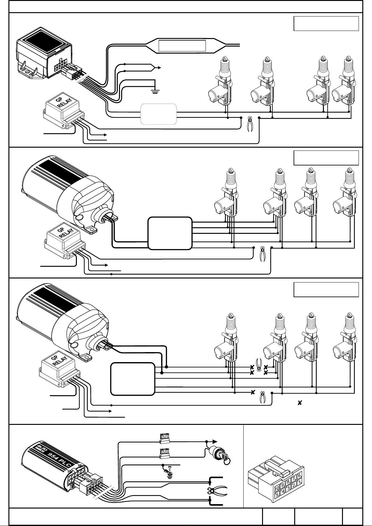
A. If Selective Unlock is not used:
B. If Neg. Out when Armed is not used: (See wiring diagram for explanation)
C. If Pager is not used, the following window options may be selected:
D. If Horn is selected:
E. If Speaker is selected:
5.0
6.0
7.0
8.0
9.0
PAGER & TRACKING OUTPUT. (SEE 3.0 & TABLE 1 note 5.1)
TURBO RUN ON MODE (SEE 3.0 & TABLE 1)
Note that this option is not available if the window winding option is
required. The output is a low current output that can be connected to
a pager or a tracking unit. It will switch to ground:
i) Five seconds after the alarm is triggered.
ii) If the hotwire input is switched to 12 volts while the vehicle is
immobilised.
iii) the end of the hijack sequence.
When selecting this option trunk release will be disabled. Use the
Blue/Grey wire to energise the relay(s) to feed power to the ignition
circuits required to keep the vehicle running after the vehicle is
turned off. The feed-points should be identified after fitting the
immobilisation. The default run-on time is 180 seconds but this can
be altered to 60 seconds using the program option - see Table 1 -
Option 5.7.
Five seconds after
The factory default is to auto rearm but auto arming can be selected.
The doors can be programmed to lock when auto arming or auto
rearming. Consult with the owner before selecting this option as it
can result in the keys being locked in the vehicle!
A siren can be used in place of a horn speaker. In this case the output
will switch low for the duration that the siren sounds. Do not connect
a horn speaker if the siren option has been selected as the speaker
and/or the alarm unit will be damaged.
The interior light switching circuit is connected to the negative door
wire (pink label marked “doors”). The light will fade on and off. The
dome light automatically coming on, can be deselected - See table 1
Option 8.3.
NOTE : If the vehicle has positive door switching this feature can still
be wired using an additional relay but without the fade facility. (SEE
WIRING DIAGRAM PAGE 1)
AUTO ARMING/AUTO REARMING (SEE 3.0 & TABLE 1 note 8.5)
SIREN/SPEAKER
INTERIOR LIGHT
.. ..
.. .
.......
..
10
11
12
13
14
15
AUTOWATCH 457 Rli ALARM/IMMOBILISER WIRING DIAGRAM
REV. 3
28/06/07
WIRE HARNESS
INTO THE VEHICLE
PRIOR TO PLUGGING
CONTROL MODULE IN
GP RELAY
PFK PART
NO.436 900
NORMALLY OPEN:
CONNECT TO
GROUND OR +12V
AS REQUIRED TO
DRIVE MOTORS #
# The 'active' polarity is the opposite
polarity of the motors at rest.
87
87a
86
85
30
+12V
CONNECT TO ‘REST STATE'
OF MOTOR WIRES
(determined by the polarity
of the motors at rest)
BLUE
BLUE UNLOCK
CUT AND INSULATE
UNLOCK
UNLOCK
GREEN
BROWN
BROWN/WHITE
LOCK
LOCK
LOCK
COMMON
DRIVERS
DOOR
MOTOR
FRONT
PASSENGER
DOOR
MOTOR
REAR
PASSENGER
DOOR
MOTORS
CENTRAL
LOCK
MODULE
(KIT)
NOTE : Following this
modification, the passenger
doors will no longer unlock
when the driver's door is
unlocked manually.
ALARM UNIT
CONNECT TO SELECTIVE UNLOCK FROM ALARM
PAGE
4 OF 4
NORMALLY
OPEN:
DO NOT
CONNECT
GP RELAY
PFK PART
NO.436 900
GP RELAY
PFK PART
NO.436 900
NORMALLY
OPEN:
DO NOT
CONNECT
87
87
87a
87a
86
86
85
85
30
30
+12V
+12V
CONNECT TO SELECTIVE UNLOCK FROM ALARM
BLUE
BLUE
BLUE
UNLOCK
UNLOCK
UNLOCK
UNLOCK
UNLOCK
GREEN
GREEN
BROWN
BROWN/WHITE
LOCKLOCK
LOCK
LOCK
LOCK
COMMON
DRIVERS
DOOR
MOTOR
DRIVERS
DOOR
MOTOR
FRONT
PASSENGER
DOOR
MOTOR
PASSENGER
AND REAR
DOOR
MOTORS
REAR
PASSENGER
DOOR
MOTORS
THIS CONFIGURATION IS IDEAL FOR MODIFYING
FACTORY FITTED CENTRAL LOCKING MOTORS
FLEX
BROWN/WHITE
+ 12 VOLTS
(FUSED 20A)
GREY
BROWN
VIOLET
YELLOW
CI65
ALTERNATING
POLARITY
CENTRAL
LOCK
MODULE
(KIT)
ALARM UNIT
BRN/WHT - UNLOCK
BROWN - LOCK
JOIN TO CORRESPONDING
CONTROL WIRES FROM ALARM
CENTRAL LOCKING
INPUT CONTROL
CONNECT TO SELECTIVE UNLOCK FROM ALARM
SELECTIVE UNLOCKING WIRING OPTIONS
DPFK 457/520
THIS CONFIGURATION IS IDEAL WHEN USING
SLAVE DOOR MOTORS OPTION 1 (A)
THIS CONFIGURATION IS IDEAL WHEN INSTALLING
A 4-DOOR CENTRAL LOCKING KIT OPTION 1 (B)
OPTION 2
1.
2.
3.
4.
5.
6.
7.
8.
9.
10.
(Black wire) Join with
black wire from pin 6.
(Black wire) Join with
black wire from pin 7.
Not used
Not used
Ground (Black wire)
(Black wire)Join with
black wire from pin 1.
(Black wire)Join with
black wire from pin 2.
Not used
Ignition (Green wire)
+12V (Red wire)
REAR VIEW
OF 10-WAY
HARNESS
IGNITION
(FUSED)
CHASSIS
CONNECT TO
+12 VOLTS
CONNECT TO A
SECURE GROUND
POINT
Ignition
switch
RED
GREEN
BLACK
BLACK (Pin 1)
BLACK (Pin 2)
BLACK (Pin 6)
BLACK (Pin 7)
CUT CIRCUIT TO BE
IMMOBILIZED AND
REJOIN VIA CIRCUIT
(30 AMP CAPABILITY)
POWER LINE COMMS IMMOBILISER
AUTOWATCH 457 Rli ALARM/IMMOBILISER WIRING DIAGRAM
REV. 3
28/06/07
Other AutoWatch Automobile Accessories manuals


