Q'STRAINT QUANTUM User manual

THE QUANTUM®SECUREMENT SYSTEM MEETS ALL CURRENT REGULATIONS FOR REAR FACING TRANSIT,
EUROPEAN DIRECTIVES AND ADA/CSA REQUIREMENTS.
USE & CARE MANUAL

2
Read All Instructions Prior to Installation
TABLE OF CONTENTS
• This manual is a comprehensive step-by-step instruction guide on how to install the QUANTUM® Securement System
and components into vehicles’floors and walls.
• Make sure to read, understand and follow all these instructions.
• To address any questions relating to installation, ordering parts, operating the QUANTUM® Securement System,
troubleshooting, maintenance, service or anything else, contact the nearest Q’STRAINT® office listed on the back page
of this manual.
• All deviations and alterations from these instructions MUST be reported to both your supervisor and Q’STRAINT®.
IMPORTANT SAFEGUARDS AND WARNINGS 3
COMPLIANCE 4
SYSTEM DEFINITIONS 58
QUICK INSTALLATION SEQUENCE 9
QUANTUM EFFECTIVE LAYOUT 1011
OPERATIONAL SEQUENCE 12
VISUAL AND AUDIO SEQUENCE 13
MAINTENANCE AND CARE 14
SERVICE 15
WARRANTY 16

3
IMPORTANT SAFEGUARDS AND WARNINGS
WARNING: While in maintenance and service mode, ALL safety features are temporarily disable, therefore keep hands, feet and
all body parts away from the QUANTUM® Securement System when activated.
• All equipment and components MUST be installed and serviced by an experienced and trained technician.
• Safety eye glasses MUST be worn whenever installing or servicing this system.
• While the QUANTUM® is in Maintenance or Service Mode, earplugs MUST be worn.
• The QUANTUM® Securement System meets all current regulations for rear facing transit, European Directives and ADA/CSA requirements.
• The QUANTUM® Securement System is a complete integrated system. Do not alter or modify it in any way and do not interchange or substitute any
components. Any deviation from these recommendations is the responsibility of the installer.
• The QUANTUM® Securement System and components have been tested in a configuration similar to the recommendations in this manual.
• The QUANTUM® Securement System and its components MUST be regularly inspected, cleaned and maintained—reference the sections in this manual
Maintenance and Service.
• Before installation, check with local transportation authorities for specific regulations, standards, requirements and minimum/maximum wheelchair location
space and emergency exit requirements.
• Before installation, inspect the underside of vehicle floor, note utilities, frames, cross-members, fuel tanks and other possible obstructions—any questions
contact the vehicle’s OEM.
• Vehicle anchor points may require reinforcement. The installer or manufacturer is responsible for ensuring anchorages are installed into suitable floor
and wall structures. Floor and wall strength MUST meet specific regulations, standards and applicable performance requirements from local transportation
authorities.
• Do NOT install anchorages or any system components into faulty materials such as corroded metal, wood, plastic or fiberglass panels.
• Regulations and standards in some countries require the installation of a backrest, shoulder and lap belt to be considered a compliant wheelchair securement
system. The QUANTUM® Securement System plus Backrest, Shoulder and Lap Belt (occupant securement—for US only) make a complete rear facing
wheelchair securement system.
• The QUANTUM® Securement System MUST be serviced by an experienced and trained technician after every Manual Release.
• Every QUANTUM® Securement System Manual Release MUST be reported to both your supervisor and Q’STRAINT®.
• The QUANTUM® Securement System MUST be serviced or replaced after every vehicle collision.
• Replace ALL system components including floor and wall anchorages that were used during a vehicle collision. Broken and worn components MUST be
replaced.
• All damages and defects MUST be reported to both your supervisor and Q’STRAINT®.
• If the QUANTUM® Securement System malfunctions or if any questions arise regarding the system’s operations, immediately contact Q’STRAINT®.
• Only use Q’STRAINT® components with this system, unless otherwise stated.
• Only use Hardware with a minimum Grade 8, which meets ASTM F835 ,SAE J429 or ASTM 574 specifications (depending on head style and drive), and coated
for adequate protection against corrosion per ISO 7253 or ASTM B117 or per customer requirements.
• The QUANTUM® Mounting Plate MUST be installed onto a flat and durable surface. ONLY use Q’STRAINT® hardware for installation.
• The images of the Mounting Plate and Supporting Plates illustrated in this manual are a representation of the Basic Mounting Plate and Basic Supporting Plates.
The Mounting Plate and Supporting Plates will vary depending on the Bus Configuration.
• When installing or servicing the QUANTUM® Securement System, protect system from contacting sharp corners and edges.
• Prevent contamination of webbing by avoiding contact with oils, gasses, polishes and chemicals.
• Worn, contaminated, or damaged webbing MUST be replaced.
• Installer is responsible for making sure the installed QUANTUM® Securement System meets all applicable regulations and standards—and that the system works
according to the instructions in the section of this manual called Testing the System.
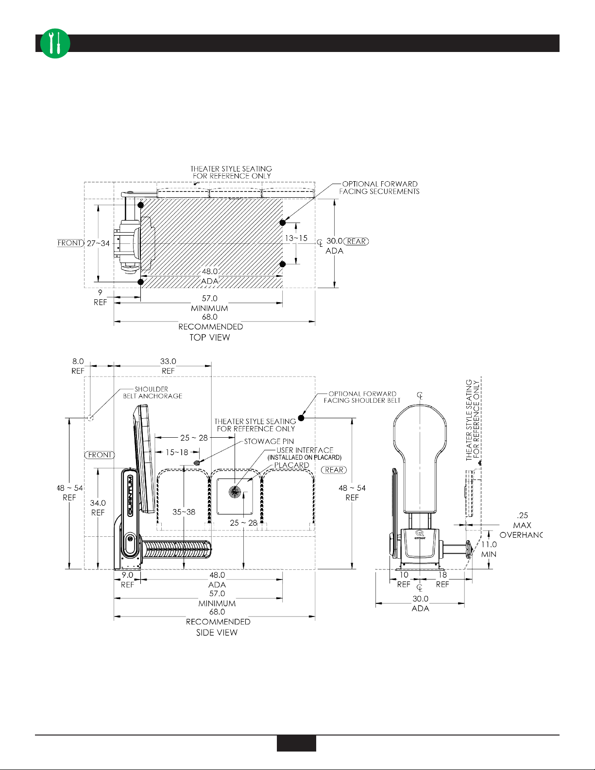
• Two QUANTUM® Securement Systems cannot be installed side by side because there MUST be a minimum pathway clearance of 22”when the QUANTUM®
Arms are at their maximum width of 33.14”—check with local transportation authorities for specific regulations, standards and requirements.
• Backrest MUST meet or exceed all current ISO 10865 regulations for rear-facing transit, European directives and the latest ADA and CSA revisions.
• Occupant securement system (shoulder and lap belt) MUST meet applicable regulations for rear facing occupant securement requirements.
• Shoulder and lap belt MUST cross occupant’s shoulder and hip, and not be held away from the occupant’s body by wheelchair components.
• If a head restraint is anchored to the vehicle, a vehicle anchored backrest restraint MUST be provided to minimize rearward deflection of the wheelchair
seatback in order to prevent an injury.
• Keep loose articles of clothing away from the QUANTUM® Rotational and Non-Rotational Arms.
SAVE THESE INSTRUCTIONS

4
COMPLIANCE
• The QUANTUM®Wheelchair Securement and Backrest meets the applicable sections of ADA 38.23, CSA
D-435, FMVSS/CMVSS 572.222, 302 and 209, European Regulations 10 and 107, EC Directive 92/28/EC,
and PSVAR 2000.

5
SYSTEM DEFINITIONS
WMD
Wheeled Mobility Device
1. QUANTUM® Base
2. Backrest
3. Passenger Securement
4. Stowage Pin
5. Occupant Interface
6. Driver Interface
5
6
4
2
3
1

6
AVAILABLE CONFIGURATIONS
8Wall
QUANTUM® -
(Street Side, US and CA)
(Curbside, UK)
(Left) (part# Q099000)
• 1 QUANTUM® Base (Left
Hand)
• 1 Mounting Plate
• 2 Supporting Plates (Bus
without Tapping Plate)
• 1 Occupant Interface
• 1 Driver Interface
• Occupant Switch
• Master Switch (On/
Off Occupant Interface)
• 2 Base Feet
• 1 Cable Kit (2-18 AWG and
13-22 AWG)
• 2 Bolts for Mounting Plate
• 1 QUANTUM® Key and
Manual Release Card
• 1 Installation Manual
• 1 Use and Care Manual
• 1 Occupant Placard
• 1 Driver Placard
QUANTUM® -
(Curbside, US and CA)
(Street Side, UK)
(Right) (part# Q098000)
• 1 QUANTUM® Base (Right
Hand)
• 1 Mounting Plate
• 2 Supporting Plates (Bus
without Tapping Plate)
• 1 Occupant Interface
• 1 Driver Interface
• Occupant Switch
• Master Switch (On/Off
Occupant Interface)
• 2 Base Feet
• 1 Cable Kit (2-18 AWG and 13-
22 AWG)
• 2 Bolts for Mounting Plate
• 1 QUANTUM® Key and Manual
Release Card
• 1 Installation Manual
• 1 Use and Care Manual
• 1 Occupant Placard
• 1 Driver Placard
8Wall
Backrest
– US, Street Side
(Left) (part# Q09B002)
• 1 Backrest with Brackets
• 1 Mounting Plate
• 2 Supporting Plates (Bus
without Tapping Plate)
• 1 Combo Occupant
Securement (Shoulder and Lap
Belt) with Retractor
• 4 Bolts for Backrest
• 2 Bolts for Mounting Plate
• 2 Bolts for Stanchion (Bus
without Tapping Plate)
• 1 Installation Manual
8Wall 8Wall
Backrest
– US, Curbside
(Right) (part# Q09B001)
• 1 Backrest with Brackets
• 1 Mounting Plate
• 2 Supporting Plates (Bus
without Tapping Plate)
• 1 Combo Occupant
Securement (Shoulder and Lap
Belt) with Retractor
• 4 Bolts for Backrest
• 2 Bolts for Mounting Plate
• 2 Bolts for Stanchion (Bus
without Tapping Plate)
• 1 Installation Manual
Backrest – CA and UK
(part# Q09B003)
• 1 Backrest
• 1 Mounting Plate
• 2 Supporting Plates (Bus without Tapping Plate)
• 4 Bolts for Backrest
• 2 Bolts for Mounting Plate
• 2 Bolts for Stanchion (Bus without Tapping Plate)
• 1 Installation Manual
SYSTEM DEFINITIONS

7
SYSTEM DEFINITIONS
One Cycle
1. From Stow Position initiate secure sequence by pressing the opperator or user interface.
2. QUANTUM®unit will beep twice alerting the operator while the capture is completed. QUANTUM®
will beep twice again after completion.
3. To release press operator or user interface.
Driver Interface
Master Switch
(On/Off Occupant Interface)
Used to disable the Occupant Interface
when not in use and enable the
Occupant Interface when in use.
Used to disable and enable the marker
lights on aisle side rotation arm.
Occupant Switch
Used for communicating, commanding
movement, indicating current
status, Securing and Releasing the
QUANTUM® from the Driver Interface.
Reset Switch, Driver and Occupant Interfaces.
Reset Switch
Used to reset {turn“OFF”(Pressed) and
“ON”(Depressed) } the QUANTUM® when
power failure occurs, when its sequence is
disrupted or once obstruction is removed.
Occupant Interface
One-touch pushbutton use by the
occupant of the WMD to Secure and
Release the QUANTUM® .
Master Switch Occupant Switch
Disable
Enable Release
Secure

8
ELECTRICAL AND OPERATIONAL REQUIREMENTS
SYSTEM DEFINITIONS
1. Continuous power source of 15 amps at 12V or 10 amps at 24V.
2. Vehicle Engine must be running (ON), Ignition signal of 12V or 24V (Interlocked).
3. Parking Brake must be engaged (ON), Parking Brake signal of 12V or 24V (Interlocked).
4. Reset switch must be depressed.
CONNECTOR
AMP SEAL (PART# 770680-1)

9
This is ONLY a quick guide, for complete installation instructions follow the directions in the “Installation Instructions”section.
NOTE: Occupant Securement (8 and 9), if applicable.
QUICK INSTALLATION REFERENCE
DRIVER NTERFACE
BACKREST
QUANTUM
FLOOR
OCCUPANT
INTERFACE
STOWAGE
PIN
OCCUPANT
SECUREMENT

10
QUANTUM EFFECTIVE LAYOUT

11
QUANTUM EFFECTIVE LAYOUT

12
OPERATIONAL SEQUENCE
8Wall
ReleaseEnable
Secure
Disable
ReleaseEnable
Secure
Disable
ReleaseEnable
Secure
Disable
ACTION IMAGE COMMENTSNo.
1
2
3
4
5
6
Stowed
Engine running and parking
brake engaged. Quantum re-
set switch must be set to ON.
Quantum is at Stowed position
Boarding
Have occupant maneuver in to
the securement area and
position facing the rear of the
bus, centered on the backrest
between the two arms.
Securing
Press secure to begin the
securement process or press
enable to allow occupant
begin process using occupant
interface
Final Capture
The flashing will change to
inform the operator to
complete the securement pro-
cess by pressing secure on the
operator interface.
Release
Unbuckle and release
brake or power on device.
Press release or press
enable to allow occupant
begin process using
occupant interface.
Occupant Securement
Offer occupant securement
and assist if necessary.
Occupant is Secured and
ready for transport.
Reset switch located on
inner side of the body
The Occupant interface
will flash green. The arm
will rotate down beeping
twice and will capture the
device
User must be centered as
much as possible for ease
of securement
Occupant is ready to exit.
Reset Switch
Activate
and Wait
30 secs.

13
VISUAL AND AUDIO SEQUENCE
Activity Image Audible
Alarm
Marker
Light
Occupant
Interface
Driver
Interface,
Release Light
Driver
Interface,
Secure Light
Master
Switch
ON Light
Master
Switch
OFF Light
Stow
Position
Deploy
in Motion
Engage
in Motion
WMD
Secured
Release
in Motion
Bump ‘n Go
Down
Sleep Mode
30 secs.
After Engine
shut/off
OFF ON Solid ON,
Solid Light
OFF ON Solid ON Solid OFF
Beep
Twice
Blinking Blinking Blinking
OFF Blinking
Blinking
Blink
5 Times
Blinking
Blink
5 Times
Blinking
Blink
5 Times
Blinking
Blinking Blinking
OFF ON Solid OFF
OFF ON Solid OFF
OFF Solid Light ON Solid OFF OFF ON Solid
ON Solid
ON Solid
Beep
Twice OFF
Beep 5
Times
Rotate Arm
Moving Out, In,
Up & Down
Blink
5 Times
ON Solid OFF
ON Solid OFF
OFF ON Solid ON Solid On Solid OFF
OFF OFF OFF OFF OFF OFF OFF
WARNING: when master switch position is set to“o”marker light along rotate arm will be disabled. Rotate arm functionality will not be aected.
Power up
30 secs
After Reset
Switch,
Depressed

14
MAINTENANCE AND CARE
Date _______________________
Company _______________________________________________________________________________________________________________
Vehicle Identification # __________________________________________
Serial Number of the QUANTUM® Securement System __________________________________________
Serial Number of the QUANTUM® Backrest __________________________________________
1. The following items MUST be inspected and serviced by an experienced and trained technician during the scheduled maintenance of the
QUANTUM® Securement System.
oClean all debris from arm extensions
oONLY use Soap and Water to Clean the QUANTUM®, Arm Extensions and Backrest, then Rinse and Dry (Arms Fully Extended)
oVerify that the QUANTUM® Securement System is working properly.
oVerify that all manual release systems are functioning properly.
oVerify that all automatic release systems are functioning properly.
oVerify that occupant securement system (shoulder and lap belts) are working properly.
oVerify that all seatbelt systems are not worn or frayed. Replace as needed.
o Verify that occupant securement system is not damaged or corroded. Replace if needed.
o Verify that floor anchorages are not damaged or corroded. Replace if needed.
o Verify that all mounting bolts are tight.
o Inspect all webbing for fraying. Replace any that have frayed.
o Inspect entire system to make sure everything is working properly and replace anything that is needed.
o DO NOT LUBRICATE ARMS.
2. Any deficiencies shall be noted below and rectified before the QUANTUM® Securement System is released to the consumer for use.
3. If the repairing technician has any issues not covered by this document or is not clear on what corrective action needs to be taken, they
MUST consult the Q’STRAINT® office listed on the back page of this manual. DO NOT make any repairs without consulting Q’STRAINT®
first.
Deficiencies Noted: _______________________________________________________________________________________________________
____________________________________________________________________________________________________________________________
____________________________________________________________________________________________________________________________
Action Taken: ____________________________________________________________________________________________________________
____________________________________________________________________________________________________________________________
____________________________________________________________________________________________________________________________
____________________________________________________________________________________________________________________________
Dealership:___________________________________________ Technician:______________________________________________

15
SERVICE
For service contact a Q’STRAINT® certified dealer.
Service Every 10,000 Cycles
WARNING: Once the QUANTUM® reaches 9,500 cycles, every time the vehicle is turned “ON” 2 Alert Beeps will be heard for 1
minute indicating that the QUANTUM® needs to be serviced soon. The QUANTUM® will still be operational. Make sure to con-
tact your authorized Q’STRAINT® dealer for a service appointment.
WARNING: While in maintenance and service mode, ALL safety features are temporarily disabled, therefore keep hands, feet
and all body parts away from the QUANTUM® Securement System when activated.
One Cycle
From Stow Position to Secure Position back to Stow Position.

16
3 YEAR WARRANTY ALL SYSTEMS, PRODUCTS & ACCESSORIES
WARRANTY REGISTRATION
In order to take full advantage of Q’STRAINT’S warranty, register your product online at: www.qstraint.com/registration
PLEASE DO NOT MAIL IN THIS REGISTRATION. Before going online, have your vehicle’s registration handy as well as the equipment’s:
Serial # _________________________ Part # __________________________
Q’STRAINT’S LIMITED WARRANTY: Q’STRAINT® warrants this product conformance to our manufacturing specifications and to be free from defects in materials and
workmanship. Q’STRAINT® or its authorized dealer will (at its sole discretion), repair or replace the defective component(s) free of charge. This warranty does not
cover the cost of assembly or disassembly, transportation, labor, or any other incidental costs involved in the removal of a defective part or the installation of the
replacement part.
Q’STRAINT® or its authorized dealers reserves the right to inspect the product to verify the claimed defect has not been caused by non-Q’STRAINT® approved
maintenance or by foreign particles or substances. This Warranty does not apply to defects that result from accident, misuse or abuse, intentional damage, fire,
flood, alteration or modification of the product, negligence, exposure, or use of the product in a manner inconsistent with its intended use.


www.qstraint.com
This manual contains the most current informaon at the me of prinng. Q’STRAINT® reserves the right to modify systems, components and content without noce.
This manual was printed on 30% post-consumer stock using vegetable oil based inks and is 100% recyclable.
© 2017 Q’STRAINT®. All Rights Reserved. QUANTUM® is a registered trademark of Q’STRAINT®, Inc.
Our products are protected under the following patents: www.qstraint.com/patents
FOR TECHNICAL SUPPORT OR TO FIND YOUR NEAREST AUTHORIZED DEALER:
QC17077 REV1
Q’Straint Europe
72-76 John Wilson Business Park
Whitstable, Kent, CT5 3QT
United Kingdom
Tel: +44 (0)1227 773035
Fax: +44 (0)1227 770035
Q’STRAINT America
4031 NE 12th Terrace
Oakland Park, FL 33334
Tel: 800-987-9987
Fax: 954-986-0021
Email: [email protected]
Q’Straint Australia
Tramanco Pty Ltd.
21 Shoebury Street,
Rocklea, Australia, QLD. 4106
Tel: +61 7 3892 2311
Fax: +61 7 3892 1819
Email: info@tramanco.com.au
Other manuals for QUANTUM
1
Table of contents
Other Q'STRAINT Automobile Accessories manuals
Popular Automobile Accessories manuals by other brands

Orlaco
Orlaco CornerEye LHD manual

AVS
AVS Headlight Covers installation instructions

DVB
DVB SRBR-02 installation manual

Fiamma
Fiamma CARRY-BIKE VW T2 Installation and use instructions and warnings

Whispbar
Whispbar K862W Fitting instructions

WeatherTech
WeatherTech No-Drill MudFlap installation instructions