AutoXray EZ-READ User manual

USERS MANUAL
EZ-READ
REVISION 2.1

WARNING: Read and understand all instructions in this manual.
Use appropriate personal safety equipment including hearing and eye
protection when using the Code Reader in or near the vehicle engine
compartment. Failure to comply can result in accidents involving fire,
electrical shock, or serious personal injury.
Electrical
• Do not allow anything to rest on the cable assembly. Do not allow
the cable assembly to be pinched. Keep the cable assembly away
from contact with heat, oil, sharp edges, or moving parts. Replace
damaged cables immediately. Damaged cables increase the risk of
electric shock.
• To reduce the risk of electrical shock do not disassemble the EZ-Read.
There are no user repairable components inside the unit.
• Please dispose of used batteries properly. Do not incinerate batteries.
Consult your local waste authority for information regarding available
recycling and/or disposal options.
Use and Care
• Stay alert, pay attention to what you are doing, and use common sense
when operating the EZ-Read. Several operational tests require the
engine in the vehicle to be running during testing. Keep all children and
visitors a safe distance from the work area.
• Keep the EZ-Read dry, clean, and free from oil and grease. Use a mild
detergent on a clean cloth to wipe the outside
of the EZ-Read, when necessary.
• Only use accessories that are recommended by AutoXray.
• Certain capture mode tests can be performed while driving the
vehicle. AutoXray recommends that the person operating the
vehicle does not use/view the EZ-Read. Always
use an assistant to operate the EZ-Read while
driving the vehicle.
Service
Service must only be performed by AutoXray repair personnel. Service or
repair by unqualified personnel may result in risk of injury, damage to the
unit, and may void your warranty. Refer to the Product Warranty Policy
section of this manual.
SAFETY PRECAUTIONS AND WARNINGS
Page 2

Safety Precautions and Warnings .....................................................2
Table of Contents ................................................................................3
Introduction .........................................................................................4
Setup / Operating Instructions...........................................................7
SCAN - OBD-II, OBD-I
SCAN - OBD-II, GM, Chrysler OBD I ...............................................13
MON - OBD-II
Readiness Test - OBD-II ...................................................................14
DATA - OBD-II, GM OBD-I, Chrysler OBD-I
View Trouble Codes - OBD-II, GM, Chrysler OBD I .........................15
Clear the Codes - OBD-II, GM, Chrysler OBD-I ...............................16
SCAN - Ford
Scan the KOEO Data - Ford.............................................................17
Scan the KOER Data - Ford .............................................................18
DATA - Ford
View the KOEO Data - Ford .............................................................21
View the Memory (Trouble) Codes - Ford ........................................22
Clear Ford Memory (Trouble) Codes................................................23
Troubleshooting
What to do When the EZ-Read Displays a
Fault/Trouble Code............................................................................24
What to do for a "Vehicle Is Not Responding" Message ..................24
Screen Contrast Problems................................................................25
How to Reset the EZ-Read...............................................................25
EZ-Read Screen Menu Trees ...........................................................26
Upgrade, Update, Specifications
EZ-Read Upgrade - Adding Capability (Phone or
Internet).............................................................................................28
Registration Card ..............................................................................29
EZ-Read Update - Loading New Software Version ..........................29
Technical Description of OBD-I and -II............................................31
Product Warranty Policy...................................................................33
Additional Products / Accessories..................................................35
Internet Access..................................................................................35
TABLE OF CONTENTS
Page 3

Thank You for buying the EZ-Read from AutoXray, the leading
provider in cost effective automotive diagnostic Code Readers.
Figure 1. EZ-Read
• AutoXray designed this elegant EZ-Scan tool with capabilities
that are the best value on the market today. The compact
design has received proprietary patents and makes these
Code Readers so simple and easy to use.
INTRODUCTION
Page 4
Display
Screen
MODE
Keys
ENTER
Key
POWER (ON/OFF)
Key CONFIG
Key
UP / DOWN
BACK / NEXT
Arrow Keys
Battery
Compartment

Your EZ-Link EZ-Read Will:
• Pull Trouble Codes and display them in plain English
• Allow you to clear Trouble Codes (on equipped vehicles)
• Reset your Check Engine Light
AutoXray has made sure your new EZ-Read is
computer safe. It WILL NOT accidentally deploy airbags, change
transmission gears, affect ABS brake performance, or fire injectors
and ignition systems.
Additional Features:
OBD-II (for 1996 and newer Domestic, Asian and European
OBD-II compliant vehicles) -
• Freeze Frame Indicate
• Display Readiness Test Status
• Show Current Trouble Codes
• Show Pending Trouble Codes
Text Styles Used In This Manual
POWER text in this font is used to designate a
button/key on the front of the EZ-Read
Config Unit text in this font is used to designate text that is
displayed on the EZ-Read screen
WARNING: the word WARNING in this font is used to
identify an operation or activity that could cause
severe property damage or personal injury
CAUTION: the word CAUTION in this font is used to
identify an operation or activity that could cause
property damage or personal injury
INTRODUCTION (CONT.)
Page 5
NOTE: the word NOTE in this font is used to identify
information that will assist you while you are
using the EZ-Read.
Arrows will be displayed at the right side of the screen to indicate
text above and/or below the current screen. Use the pand q
arrow keys to view the text
NOTE: During the procedures in this manual,
display all the available menu options
by using the pand qarrow keys.
Small arrows will be displayed on the screen when there
are more options available.
INTRODUCTION (CONT.)
Page 6
This section gives the information you need to set up and operate
your EZ-Read EZ-Read:
• Install New Batteries
• Configure the EZ-Read for Your Vehicle
• Set the Display Units (SAE/Metric)
• Connect the EZ-Read to Your Vehicle
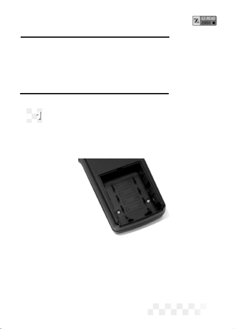
Install New Batteries
The EZ-Read EZ-Read is powered by 4 AA batteries.
Before the EZ-Read is used the first time, you need to
install batteries in the unit.
Make sure the batteries are put in according to the dia-
gram on the bottom of the battery compartment. Refer to
the illustration below.
Figure 2. Battery Compartment
• If the screen becomes too dim to view, the batteries need to be
replaced. Replace all four batteries to avoid unit malfunction.
When it is time to change the batteries, the Data Holder
Feature will save all Data and configuration information if fresh
batteries are installed immediately after removing the old ones.
CAUTION: Leaving used or dead batteries in the EZ-Read beyond
SETUP / OPERATING INSTRUCTIONS
Page 7

the battery date may result in damage to the unit.
• As long as good batteries are in the EZ-Read, the vehicle
engine configuration and data will remain in the EZ-Read’s
memory, even after the unit is
powered off.
• Operational data, Trouble Codes, and all remaining scanned
information will remain in memory until the unit is reconfigured.
APower Miser Feature automatically powers the unit OFF
after 30 minutes of no activity.
• Refer to “Screen Contrast Problems” on page 25, if needed.
Configure the EZ-Read for Your Vehicle
Before the EZ-Read is used, it must be configured for
your specific vehicle. Don’t worry, it only takes a few steps.
1. Press POWER to turn the unit ON, then press CONFIG.
2. Make sure 1-Config Unit is displayed on the screen, then
press ENTER.
3. Use the pand qarrow keys until the correct vehicle manufac-
turer name is highlighted, then press ENTER to select it
(select OBD-II Generic if your specific OBD-II
manufacturer is not listed).
4. For OBD-I vehicles, use the arrow keys to highlight the
number that matches the 8th character from the VIN
code on the vehicle. Press ENTER to select the proper
character.
NOTE: After the unit is configured, it will Initialize then display
the opening screen. Continue with Section 3 to set the
display units.
SETUP / OPERATING INSTRUCTIONS (CONT.)
Page 8

Adjust the Display Contrast
The contrast on your EZ-Read 1000/2000 can be adjusted
for easier viewing under different lighting conditions.
NOTE: Due to the differences in design not all products
support this feature.
1. To adjust the contrast of the screen press CONFIG key.
2. Use the pand qarrow keys until 2-System Config is
displayed, then press ENTER.
3. Use the pand qarrow keys until 3-Contrast Adj is dis-
played, then press ENTER.
4. Use the tand uarrow keys to adjust screen contrast. (Fine
adjustment)
5. Use the pand qarrow keys for course adjustment.
6. Press the CONFIG or ENTER key to save settings and
return to the Opening screen.
NOTE: If scanner is left in direct sunlight the Display can turn
completely black. Should this happen put the scanner in a
cool dark place for approx. 10 to 15 minutes the Display
should return to normal.
Set the Display Units (SAE/Metric)
The EZ-Read EZ-Read can be set up to display in SAE or
Metric units. The default setting is SAE. Go to Section 4
if you do not need to change the display units.
1. To change the unit of measure, press CONFIG from the
initial screen.
2. Use the pand qarrow keys until 2-System Config is
displayed, then press ENTER.
3. Use the pand qarrow keys to select 1-SAE/Metric, then
press ENTER.
SETUP / OPERATING INSTRUCTIONS (CONT.)
Page 9
Page 10
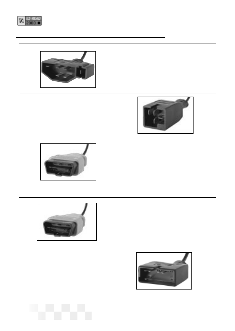
Ford Connector
Works with OBD-I 1983-1995
Ford vehicles with EEC-IV
computers.
Chrysler Connector
Works with OBD-I 1983-1995
Chrysler vehicles with SCI
connectors
OBD-II Manufacturer
Specific Connector (Blue)
For 1994-1995 GM OBD-I vehicles
with a 16 pin connector, as well
as for future OBD-II functions to be
released at a later date.
OBD-II Generic
Connector (Yellow)
This standardized cable is
used to scan 1996 and newer
Domestic, Asian, and
European vehicles.
GM Connector
Works with OBD-I 1982-1995
vehicles with a 12 pin ALDL.
SETUP / OPERATING INSTRUCTIONS (CONT.)

Page 11
4. Use the tand uarrow keys to select 1-SAE or 2-METRIC
then press ENTER to select the highlighted choice (or press
the CONFIG Key to Cancel and return to the initial screen).
Connect the EZ-Read to Your Vehicle
The EZ-Read EZ-Read communicates with the computer
and sensors in your vehicle through a special
connection cable. The EZ-Read cable is plugged into a
connector on the top of the EZ-Read, and
into a computer interface connection in your vehicle.
1. Locate the vehicle computer connection:
•[OBD-II / GM] On OBD-II and GM vehicles, the connector
is usually located under the drivers side of the dashboard.
On some vehicles, the connector is located behind the kick
panels, ashtray, or radio.
•[Ford / Chrysler 83-95] The connector on Ford and Chrysler
vehicles is usually located in the engine
compartment, along the outside perimeter of the engine com-
partment, or by the shock absorber towers.
NOTE: For additional connection location information, including the
“OBD Connector Locations Database,” please look
at the Customer Support page on the AutoXray
web site (www.autoxray.com ).
2. Make sure that all the pins are straight and that the connecting
surfaces are free of oils, grease, and moisture.
CAUTION: Do not force the cable connector into the scanner or
into the vehicle computer connection.
3. Push the scanner cable and vehicle connectors together firmly.
•[Ford] The EEC-IV Ford connector has a trapezoid shaped
connector and a small square connector next to it. Make sure
SETUP / OPERATING INSTRUCTIONS (CONT.)

both connectors are correctly plugged into the scanner
cable connector.
NOTE: Make sure the scanner cable and vehicle connectors are
always properly seated during all test procedures.
4. Insert the EZ-Read cable connector into the top of the scanner.
Page 12
SETUP / OPERATING INSTRUCTIONS (CONT.)
Page 13
Before You Start
•Before scanning a vehicle, the EZ-Read EZ-Read must be
correctly configured for your vehicle. Refer to “Setup / Operating
Instructions” on page 7 if you need to configure the EZ-Read.
Scanning the Vehicle
1. Press POWER to display the EZ-Read EZ-Read opening
screen.
2. Turn the vehicle ignition key to ON or start the engine.
3. Press SCAN.
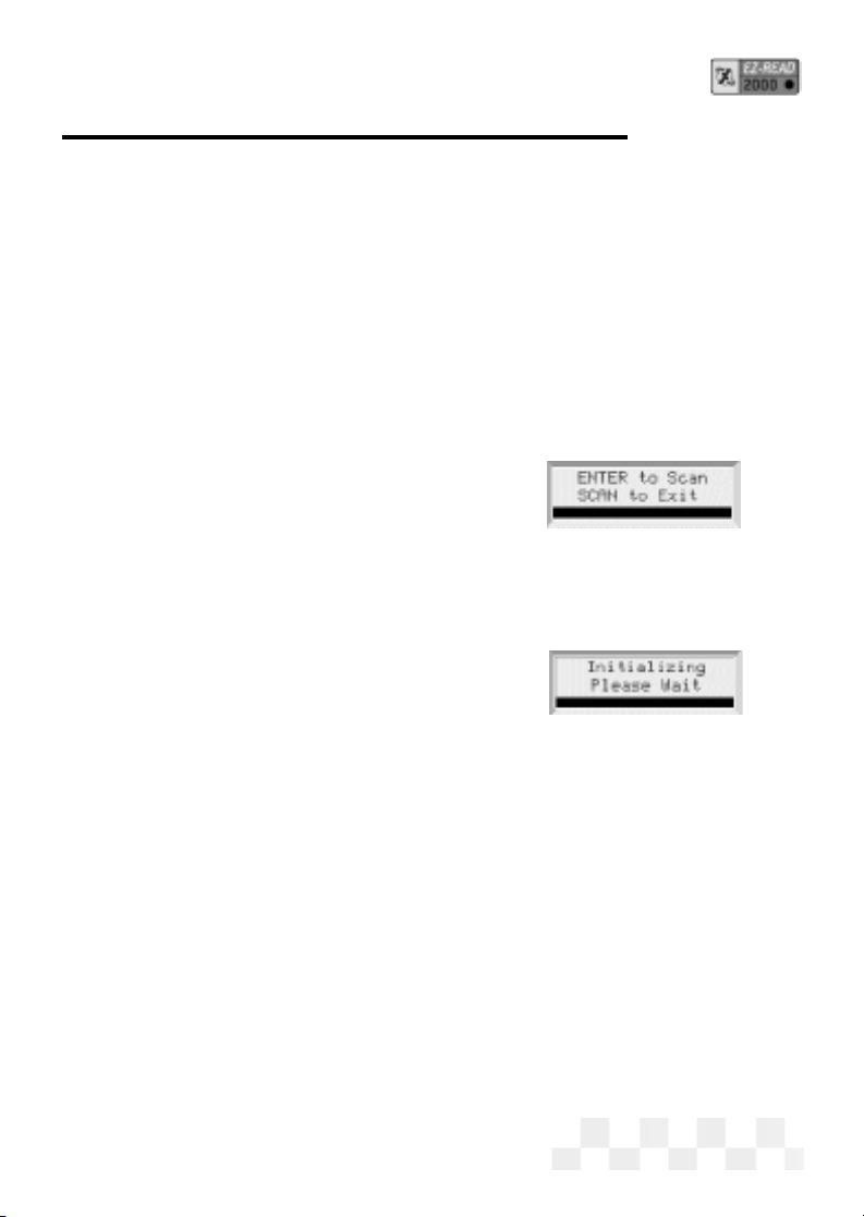
• When the EZ-Read is ready to scan
the vehicle, ENTER to Scan will
be displayed on the screen. Press
ENTER to start scanning the vehicle computer/sensors.
(Pressing SCAN again will take the unit out of Scan
mode and display the opening screen.)
•[OBD-II] Before an OBD-II vehicle is
scanned, the vehicle computer and
the EZ-Read EZ-Read will initialize,
do a protocol check, then do Readiness Tests to make sure
the vehicle emission control system is working correctly.
(VPW, PWM, ISO 9141, and Keyword 2000 protocols are all supported.)
4. [OBD-II] The EZ-Read will indicate the MIL status (Malfunction
Indicator Lamp, or Check Engine Light), ON or OFF. If there are
Trouble Codes stored in the OBD-II system, the scanner will
display the codes as they are read from the vehicle computer.
(These codes can also be viewed later. See “View Trouble
Codes-OBD-II” page 15.)
5. After the EZ-Read has read all the data from the vehicle, the Scan
Successful message will be displayed on the screen. If the
EZ-Read could not read all the data from the computer or the
vehicle sensors, an error message will be displayed.
SCAN - OBD-II, GM, CHRYSLER OBD-I
Page 14
Before You Start
•[OBD-II] Your scanner must be connected, and the key in the ON
position, before viewing OBD-II Readiness Test data. If MON is
pressed, and the vehicle has not been scanned, the scanner will
display Press the Scan key to Scan New Data. Refer to
“Scanning the Vehicle” on page 12.
1. Press POWER to display the EZ-Read scanner opening
screen.
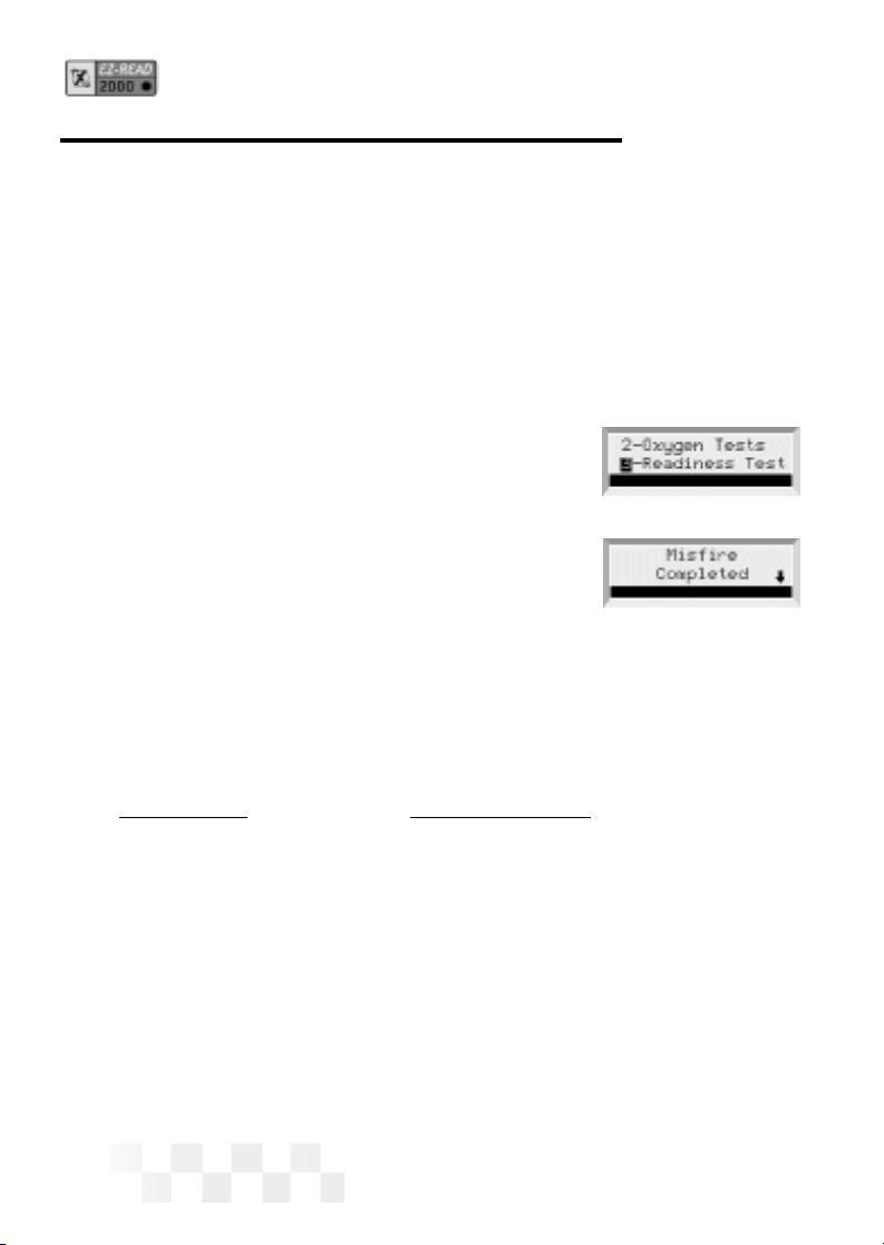
2. Press MON to display Monitor menu.
Use the pand qarrow keys until 3-
Readiness Test is highlighted, then
press ENTER.
3. The name of the Readiness Test will be
displayed, followed by its status. Status is
either Completed, Not Completed, or Not
Supported.
• A down arrow on the screen indicates other test results.
Use the pand qarrow keys to view these other test
results.
The following Readiness Tests are supported by the scanner:
CONTINUOUS NON-CONTINUOUS
Misfire Monitoring Catalyst Monitoring
Fuel System Monitoring Heated Catalyst Monitoring
Comprehensive Evaporative System Monitoring
Component Monitoring Secondary Air System Monitoring
A/C System Refrigerant Monitoring
O2 Sensor Monitoring
O2 Sensor Heater Monitoring
EGR System Monitoring
4. Press MON to exit the Readiness Test and display the opening
screen.
READINESS TEST - OBD-II
Page 15
Before You Start
• Your vehicle must be scanned before clearing trouble
codes. If DATA is pressed, and the vehicle has not been
scanned, the EZ-Read will display Press the Scan
key to Scan New Data. Refer to “Scanning the
Vehicle” on page 12.
Viewing Trouble Codes
1. If the EZ-Read is not ON,press POWER to display the
opening screen.
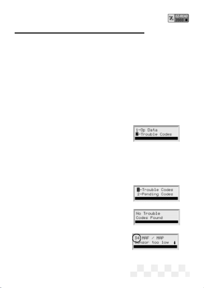
2. [OBD-II] Use the pand qarrow keys
until 2-Trouble Codes is highlighted,
then press ENTER.
[GM OBD-II] is 3 - Trouble Codes.
3. [OBD-II] OBD-II vehicles read both
Pending Codes (codes that have only
been detected once by the vehicle
computer) and Trouble Codes (codes
that have been detected multiple times).
Press ENTER to select either 1-
Trouble Codes or 2-Pending
Codes.
4. If no Trouble Codes are in the vehicle’s
computer, No Trouble Codes
Found will be displayed.
If a Trouble Code is detected, the
fault and its description will be dis-
played on the scanner screen. The
fault code number will be displayed
in the upper left corner of the
screen.
• A down arrow on the screen indicates more information.
VIEW THE TROUBLE CODES - OBD-II, GM, CHRYSLER OBD-I
Page 15
Page 16
Use the pand qarrow keys to view the additional text.
• Use the tand uarrow keys to view any other
Trouble Codes.
CLEAR THE CODES - OBD-II, GM, CHRYSLER OBD-I
Before You Start
• Clearing Trouble Codes will remove any Trouble Codes from
the vehicle’s computer. You can use this feature to make
sure vehicle repairs were done correctly by doing
a new scan after clearing the codes.
• Your vehicle must be scanned before clearing trouble codes.
If DATA is pressed, and the vehicle has not been
scanned, the EZ-Read will display Press the Scan
key to Scan New Data. Refer to “Scanning the
Vehicle” on page 12.
Clearing Trouble Codes
1. Make sure the EZ-Read EZ-Read cable is correctly connected to
the EZ-Read and to the vehicle, the
engine is OFF, and the vehicle ignition
key is ON, then press POWER.
2. [OBD-II] Use the pand qarrow keys
until 4-Clear Data is highlighted, then
press ENTER.
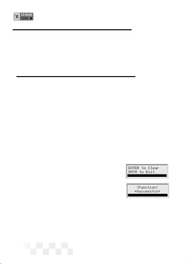
3. ENTER to Clear will be displayed on the screen. Press
ENTER to clear all the codes in the vehicle’s computer.
(Pressing DATA again will take the unit out of Data mode and
display the opening screen.)
4. After the codes have been cleared, Function Successful
will be displayed. Press DATA to display the opening screen.
VIEW THE TROUBLE CODES - OBD-II, GM, CHRYSLER OBD-I (CONT.)
SCAN THE KOEO DATA - FORD
Before You Start
• Before scanning a vehicle, the EZ-Read scanner must be
correctly configured for your vehicle. Refer to “Setup /
Operating Instructions” on page 8 if you need to configure
the scanner.
Key ON, Engine OFF (KOEO) Scan
The KOEO scan causes the vehicle EEC-IV computer to actuate
the sensors and test the different computer controlled functions of
the vehicle. The KOEO test will detect faults at the time of testing
(hard faults) and intermittent faults stored as
Memory Codes.
1. Run the engine until it is at normal operat-
ing temperature.
2. Make sure ALL electrical loads (air condi-
tioning, radio, blower fan, etc.) are OFF.
3. Connect the EZ-Read scanner cable to the
scanner and to the vehicle EEC-IV computer
connector, then press POWER to display
the EZ-Read scanner opening screen.
4. Make sure the vehicle ignition key has
been OFF for at least ten seconds. Turn the
ignition key to ON, then press SCAN.
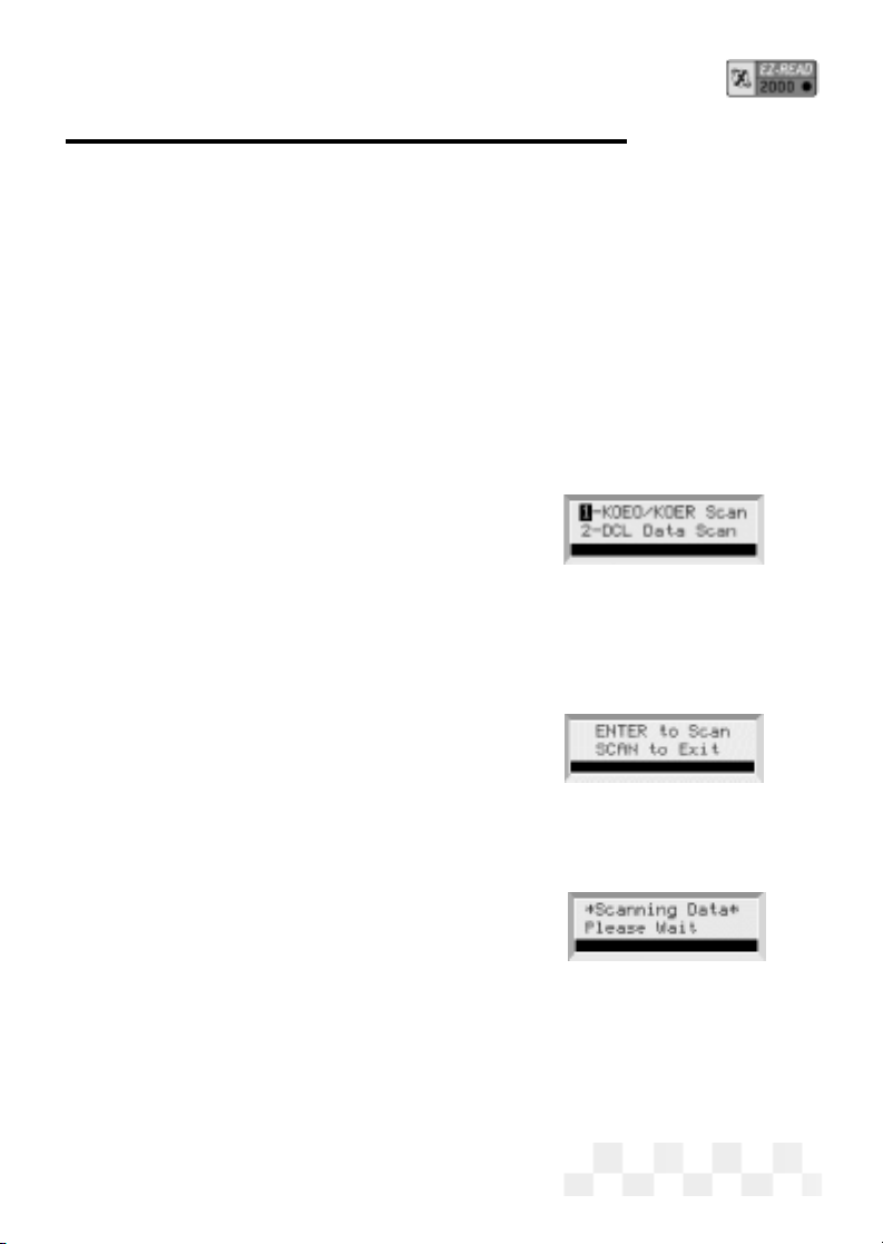
• Vehicles that support DCL will
display a Scan menu. Make sure
1-KOEO/KOER Scan is highlighted,
then press ENTER.
5. When the scanner is ready to scan the vehi-
cle, ENTER to Scan will be displayed on
the screen. Press ENTER to start scanning the vehicle comput-
er/sensors. (Pressing SCAN again will take the unit out of Scan
mode and display the opening screen.)
Page 17

Page 18
6. Scanning Data will be displayed while the KOEO codes and
memory codes are retrieved from the vehicle computer. A normal
scan can take up to three minutes.
7. After the scanner has read all the data from the vehicle, the
Scan Successful message will be
displayed on the screen, followed by the
opening screen.
SCAN THE KOER DATA - FORD
Before You Start
• Before scanning a vehicle, the EZ-Read scanner must be
correctly configured for your vehicle. Refer to “Setup /
Operating Instructions” on page 7 if you need to configure
the scanner.
• Make sure to read these instructions completely before the
KOER test is started. Several user interactions may be
required during the scan. If these steps are not completed
correctly, the engine computer will store a Trouble Code as
if the system was not functioning properly. If one of these
trouble codes are stored, repeat the scan with the neces-
sary steps to eliminate the problem. For example, the error
RPM too low during KOER test can be corrected
by pressing the gas pedal to the floor during the Dynamic
Response section of the scan.
Key ON, Engine Running (KOER) Scan
The KOER scan causes the vehicle EEC-IV computer to test the
different sensors and computer controlled functions while the
vehicle engine is running.
SCAN THE KOEO DATA - FORD (CONT.)

Page 19
1. Run the engine until it is at normal operating temperature.
2. Make sure ALL electrical loads (blower fan, air conditioning,
radio, etc.) are OFF.
3. Connect the EZ-Read scanner cable to
the scanner and to the vehicle EEC-IV
computer connector, then press
POWER todisplay the EZ-Read scanner opening screen.
4. Make sure the vehicle ignition key has been OFF for at least ten
seconds. Turn
the ignition key to start the engine, then press SCAN.
• Vehicles that support DCL will display a Scan menu. Make
sure 1-KOEO/KOER Scan is highlighted, then press
ENTER.
5. When the scanner is ready to scan the
vehicle, ENTER to Scan will be
displayed on the screen. Press
ENTER to start scanning the vehicle
computer/sensors. (Pressing SCAN again will take
the unit out of Scan mode and display the opening screen.)
6. Scanning Data will be displayed
while the vehicle computer is scanned.
A normal scan can take up to five min-
utes.
• Vehicles equipped with a Power Steering Pressure Switch -
Turn the steering wheel 1/2 turn and release, when prompt-
ed.
• Vehicles equipped with a manual transmission - Push the
clutch in during the entire test.
• Vehicles equipped with 7.3 liter diesel engines - Press the
accelerator to the floor for the entire test.
SCAN THE KOER DATA - FORD (CONT.)

Page 20
• Vehicles equipped with a Brake ON/OFF Switch - Press and
release the brake, when prompted.
7. If the vehicle is equipped with an automatic transmission, place
the car into Drive and then back into Park, when prompted.
8. If Dynamic Response is displayed,
briefly accelerate the engine to wide
open throttle. (Goose test)
9. After the scanner has completed the
KOER scan, the Scan Successful
message will be displayed on the screen,
followed by the opening screen.
• If these steps are not completed
correctly, the engine computer will store a Trouble Code as if
the system was not functioning properly. If one of these trou-
ble codes are stored, repeat the scan with the necessary
steps to eliminate the problem. For example, the error RPM
too low during KOER test can be
corrected by pressing the gas pedal to the floor during the
Dynamic Response section of the scan.
SCAN THE KOER DATA - FORD (CONT.)
Table of contents


