SinoCastel IDD-212B User manual

IDD-212B User Manual
(Rev. 2.1)
Sinocastel Co., Ltd
November, 2013

IDD-212B User Manual
1
Contents
1. Introduction....................................................................................................................................2
2. Specifications ................................................................................................................................3
2.1 External Interface..................................................................................................................................3
2.2 Status Indicator ..................................................................................................................................... 3
2.3 Technical Parameters ............................................................................................................................4
3. Device Configuration .....................................................................................................................5
3.1 PC Tool ................................................................................................................................................5
4. Installation Instruction....................................................................................................................6
4.1 OBD Port..............................................................................................................................................6
4.2 Device Installation ................................................................................................................................7
4.3 Login “VRM Coach” ............................................................................................................................7
4.4 Initialization........................................................................................................................................ 11
5. Functions.....................................................................................................................................15
5.1 OBD Protocols....................................................................................................................................15
5.2 Location Inquiry.................................................................................................................................. 15
5.3 Regular GPS Data Reporting............................................................................................................... 15
5.4 Regular G-Sensor Data Reporting........................................................................................................ 15
5.5 Regular Diagnostic Data Reporting .....................................................................................................15
5.6 DTCs Reporting.................................................................................................................................. 15
5.7 Diagnostic Functions........................................................................................................................... 15
5.8 Data storage/Supplementary Report in Dead zones .............................................................................. 16
5.9 Trip Mileage....................................................................................................................................... 16
5.10 Trip Fuel Consumption...................................................................................................................... 16
5.11 Driving behavior monitoring ............................................................................................................. 16
5.12 Alarms and Events Reporting ............................................................................................................ 16
5.13 Remote Configuration ....................................................................................................................... 16
5.14 PC Tool Configuration ...................................................................................................................... 17
6. Disclaimer....................................................................................................................................18
7. Warranty......................................................................................................................................19
8. Statement....................................................................................................................................20

IDD-212B User Manual
2
1. Introduction
IDD-212B is an intelligent on-board diagnostic box based on OBD II/EOBD standard with
Bluetooth module, it could read various kinds of data including diagnostic info, mileage, fuel
consumption and driving behavior, and real time display on Android/iOS/WinCE
PND/CPND/Smart phone via Bluetooth.
Packing List
Parts name Quantity Note
IDD-212B OBD Dongle 1 ●
USB Configuration Cable 1 ○
User Manual 1 ●
G-Mouse (HT-166U) 1 ○
OBD extension cable 1 ○
Note: ● Standard configuration ○Optional configuration
(Optional accessories will not be included if there is no indication in the order)

IDD-212B User Manual
3
2. Specifications
2.1 External Interface
Product appearance as follows:
Standard OBD Connector
It is used to connect to the 16 pin on-board Diagnostic Link Connector (DLC).
The vehicle OBD system is able to communicate with an external device which has the same
protocol via this connector.
G-Mouse /Configuration Interface
This is a multifunction interface which is used for parameters configuration or connecting
the G-Mouse
2.2 Status Indicator
Indicator Color Status
Power LED Red Solid on - Power on
Bluetooth Orange
Blinking every 1 time– Bluetooth try to connect
Blinking every 2 times– Bluetooth connected successfully
Blinking every 3 times– Bluetooth connected failed
Solid off – Bluetooth off

IDD-212B User Manual
4
OBD LED Green
Blinking – Trying to communicate with on-board system
Solid on – Successful OBD communication
Solid off – No OBD communication
G-Mouse
LED Green
Blinking - GPS signal is good
Solid on - Searching for GPS signal
Solid off – GPS off
2.3 Technical Parameters
Mechanical Size 46mm (L) x 43mm (W) x 26mm (H)
Weight 35g
Interface OBD interface
RS-232 interface
Data transmission Bluetooth
Storage 16MB FLASH, store up to 300 hours trip data
OBD protocol
SAE J1850 PWM
SAE J1850 VPW
ISO 9141-2
ISO 14230-4
ISO 15765-4
Power
Working
Voltage 9-16VDC
Working
Current
Sleep mode: <20mA@12VDC
Bluetooth
Specification: V3.0/4.0+EDR,Class II
Frequency: 2.4-2.48GHz
Modulation: GFSK、∏/4-DQPSK、8DPSK
Range: 10m (Max. no shield)
Sensitivity: -90dBm@GFSK
-90dBm@∏/4DQPSK

IDD-212B User Manual
5
-83dBm@8DPSK
-92dBm@BLE
Antenna: built in
3 axis Accelerometer +/-2g, +/-8g, driving behavior detection
LED Indication Bluetooth/OBD/Power indication
Buzzer System status/Alarm indication
Environment
Working
Temperature -30 ~ +70℃ ℃
Storage
Temperature -40 ~ +85℃ ℃
Humidity 5%~95%(no frog)
3. Device Configuration
3.1 PC Tool
Download USB driver and PC Tool at http://www.sinocastel.com/en/Downloads/. Install the
USB driver and PC Tool on your PC.
Connect device to PC through USB configuration cable, open the OBD PC Tool, configure the
parameters refer to the PC Tool User manual.

IDD-212B User Manual
6
4. Installation Instruction
4.1 OBD Port
In general, the OBD port is located in the driver or passenger cabin, from the edge of
dashboard on driver side to the border of 300mm. It is easy to touch by sitting in the driver's seat;
the preferred location is within the area from steering post to the vehicle centerline.
IDD-212B User Manual
7
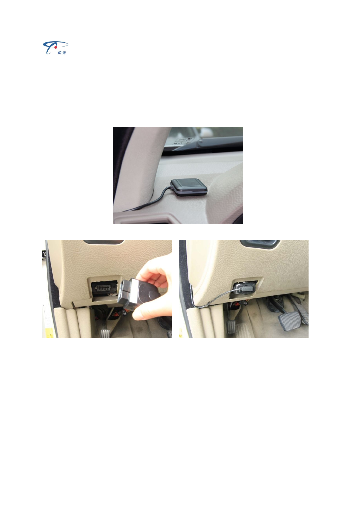
4.2 Device Installation
Before installing the device, please make sure device has been configured with necessary
parameters including network parameters and other parameters.
Park the car and make sure engine is off, connect the G-Mouse to the device. Fix the
G-Mouse above the dashboard horizontally; make sure no mental shielding above them.
Plug the device into OBD port
Start engine, with successful OBD communication the OBD light changes its status to solid
on and comes 2 beeps. Then device begins to connect VRM Coach, with successful network
registration the Bluetooth light change its status to slow blinking, and with successful login there
comes 3 beeps. GPS light blinking indicates that the device has got its location.
If OBD light keeps blinking and comes 6 beeps it means that device is not compatible with
the vehicle.
4.3 Login “VRM Coach”

IDD-212B User Manual
8
Before login “VRM Coach”, need to disconnect other devices via Bluetooth connection and
pair with IDD-212B.
Login “VRM Coach” after IDD-212B is connected via Bluetooth:

IDD-212B User Manual
9

IDD-212B User Manual
10
Input User name and password, it will show below main interface:

IDD-212B User Manual
11
4.4 Initialization

IDD-212B User Manual
12
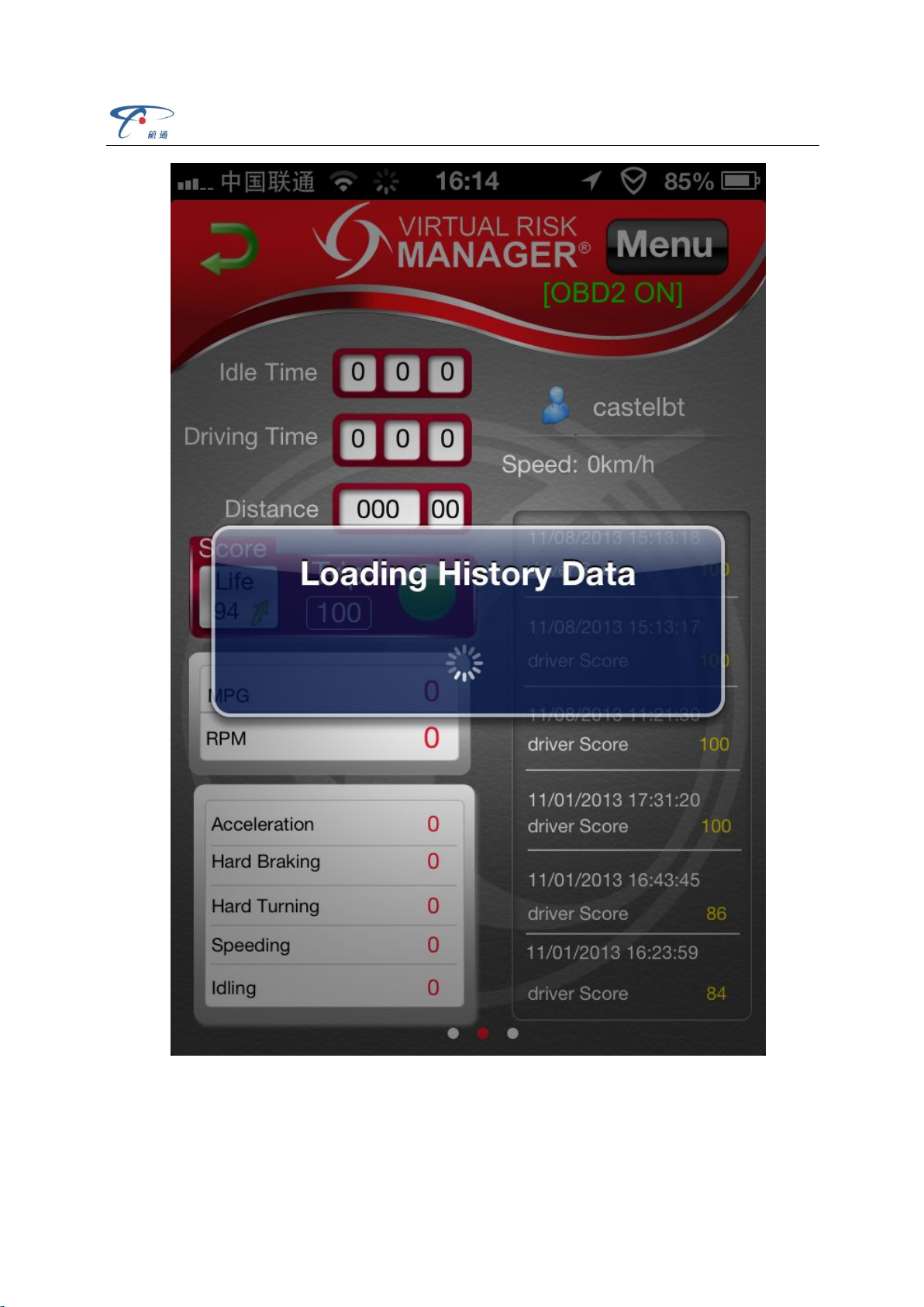
OBD will be initialized automatically when it connects to “VRM Coach” the first time
It will load history data first if the device stored some history data:
IDD-212B User Manual
13
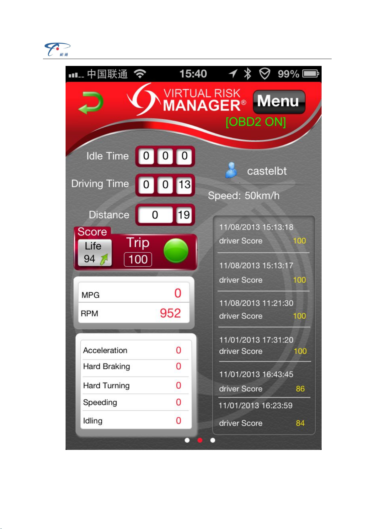
Start to upload the new data after history data uploaded:
IDD-212B User Manual
14
We advise you to drive the car for at least 10 minutes with the first installation.

IDD-212B User Manual
15
5. Functions
5.1 OBD Protocols
The device supports all the OBD II standards below:
ØJ1850-PWM
ØJ1850-VPW
ØISO 9141-2
ØISO 14230-4 (KWP2000)
ØISO15765-4(CAN)
5.2 Location Inquiry
Upon receiving location inquiry command from server or via SMS, device reports GPS data
immediately.
5.3 Regular GPS Data Reporting
Device reports GPS data according to configured time interval.
5.4 Regular G-Sensor Data Reporting
Device reports G-Sensor data according to configured time interval.
5.5 Regular Diagnostic Data Reporting
Device is able to read variety of vehicle diagnostic data, including vehicle speed, engine
RPM, engine coolant temperature, mass flow air, etc, and reports up to 10 types of diagnostic
data according to configured time interval.
5.6 DTCs Reporting
Device is able to read vehicle pending and stored DTCs, and freeze frame data. The backend
server analyzes and displays the DTCs for users on time to avoid high repairing cost.
5.7 Diagnostic Functions

IDD-212B User Manual
16
The device is able to read vehicle pending DTCs and stored DTCs, freeze frame data and a
variety of diagnostic data. The backend server analyzes and displays the DTCs for users on time
to avoid high repairing cost.
It is also able to clear vehicle DTCs and MIL according to customer’s requirements.
5.8 Data storage/Supplementary Report in Dead zones
When there is no Bluetooth signal or Bluetooth signal is poor, GPS and OBD information
are stored, and reported after signal recovery.
5.9 Trip Mileage
At the end of the trip, device will report the driving mileage to the server.
5.10 Trip Fuel Consumption
At the end of the trip, device will report the fuel consumption to server.
5.11 Driving behavior monitoring
Real-time monitor bad driving behavior, including Speeding, High RPM, Hard Acceleration,
Hard Brake, Excessive Engine Idle Time
5.12 Alarms and Events Reporting
ØHigh ECT
ØSpeeding
ØHigh RPM
ØHard acceleration
ØHard brake
ØLow power
ØIdle engine
ØTowing
ØPlug indication
ØExcessive exhaust emission
5.13 Remote Configuration

IDD-212B User Manual
17
Users can configure device via VRM Coach
5.14 PC Tool Configuration
Users can configure device or update firmware through PC Tool.

IDD-212B User Manual
18
6. Disclaimer
This user manual only applies to IDD-212B device.
This product only applies to the vehicles with OBD II/EOBD equipped.
This product strictly follows the standard of ISO15031, it shall not cause any harm or affects
on vehicles, if there is an exception, please remove the device immediately.
G-Mouse receives has GPS located function. The poisoning function may be affected in
electromagnetic shielding area or bunker place.
The device has a built-in wireless communication module. It should be used as far as
possible away from fuel depots, chemical plants and other areas could cause an explosion. Most
sensitive to external RF sites (such as gas stations, hospitals and school, etc.) may be equipped
with radio frequency jamming equipment; some functions may be affected in the interference
area.
To make sure the products works well, please use the original accessories.
This manual is based on the “as-is” situation. CASTEL will not guarantee the accuracy,
reliability and content of the handbook. Also Castel reserves the right to amend or withdrawn this
manual without any prior notification.

IDD-212B User Manual
19
7. Warranty
If product got quality problem within the warranty period, please bring the product together
with a valid warranty card and purchase invoice to the dealer for checking. Please do not
disassemble this product, this may result in damage, CASTEL will not be responsible for those
problem.
1 year of warranty since purchase time and life-long maintenance. For Failure or damage
due to incorrect operation or not following the instruction, CASTEL will provide paid
maintenance within warranty period.
User name:
Contact number:
Address:
Post code:
Purchasing date:
Serial number:
Remark:
Please keep this card carefully in order to better serve you.
Distributor (Company Chop)
Maintenance Records
Product Model:
Date
Faults and maintenance of records Maintenance
(Signature) User
(Signature)
Fault Description Maintenance
Note: This form must be carefully completed.
Table of contents
Other SinoCastel Diagnostic Equipment manuals


