Autronica GR-7600/V2 User manual

WEL‐Commissioning‐Handbook‐eng.docx
Commissioning Guide
Wireless Emergency Lighting
GR-7600/V2

COPYRIGHT©
Thispublication,orpartsthereof,maynot
bereproducedinanyform,byanymethod,
foranypurpose.
AutronicaFireandSecurityASandits
subsidiariesassumenoresponsibilityfor
anyerrorsthatmayappearinthe
publication,orfordamagesarisingfromthe
informationinit.Noinformationinthis
publicationshouldberegardedasa
warrantymadebyAutronicaFireand
SecurityAS.Theinformationinthis
publicationmaybeupdatedwithoutnotice.
Productnamesmentionedinthis
publicationmaybetrademarks.Theyare
usedonlyforidentification.

Commissioning Guide – 116-GR-7600/V2 Wireless Emergency Lighting
‐3‐
WEL‐Commissioning‐Handbook‐eng.docx
1. INTRODUCTION.........................................................................................................................................5
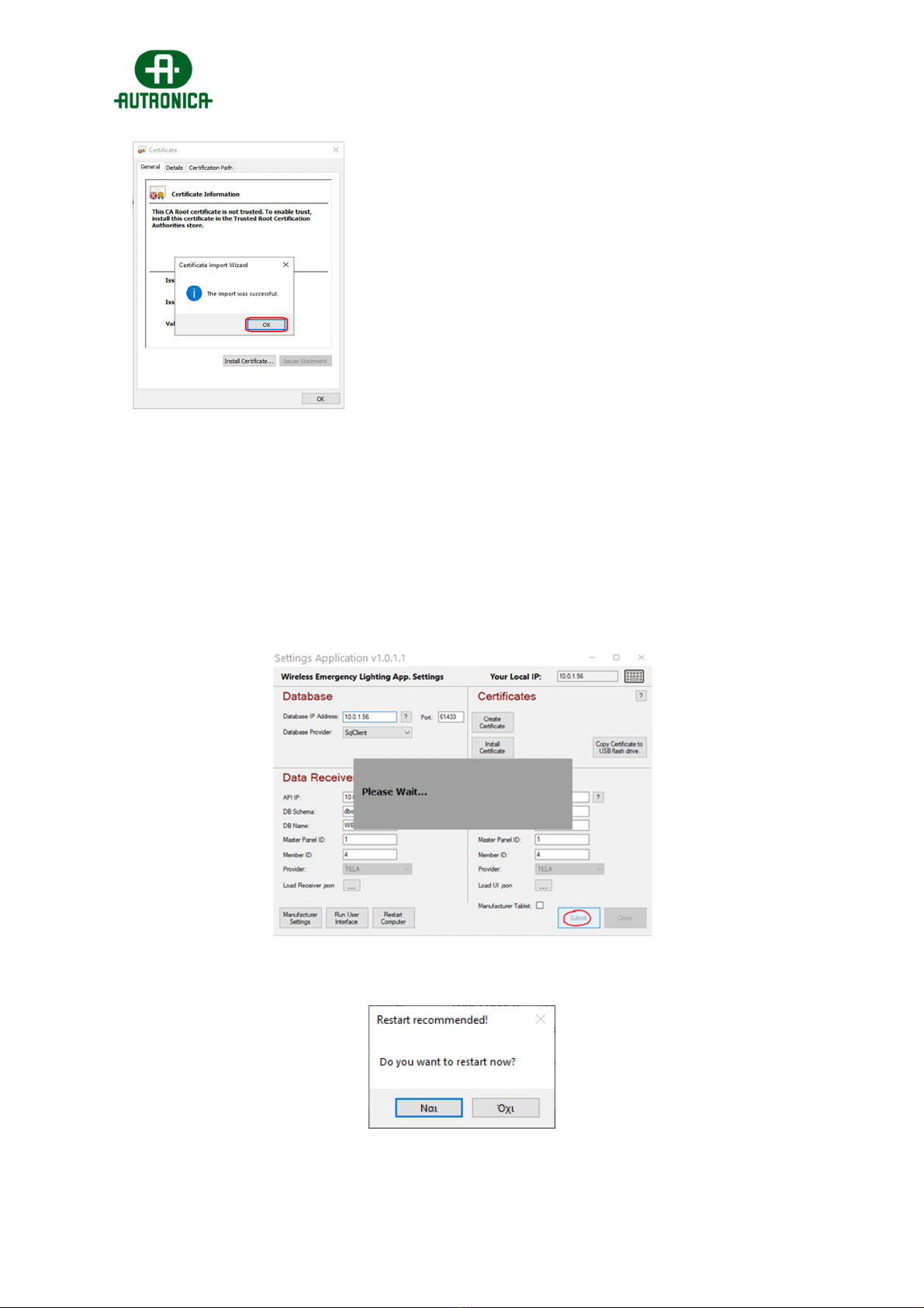
2. INSTALLING SOFTWARE APPLICATION 116-GR-7600/V2............................................................5
3. SPECIFICATIONS AND TERMS...........................................................................................................11
4. USER MANAGEMENT............................................................................................................................13
5. COMMISSIONING....................................................................................................................................14
5.1Before starting.....................................................................................................................................14
5.2Spectrum Analyzer.............................................................................................................................16
5.3Connecting 116-GR-7603/V2 Ethernet + Wifi Gateway..............................................................18
ForEthernetconnectivity:................................................................................................................20
ForWi‐Fi(WPA2/PSK)connectivity:.................................................................................................20
ForWi‐Fi(WPS)connectivity:.........................................................................................................s21
5.4Connecting a 116-GR-7607/V2 or 116-GR-7605/V2 as USB Gateway....................................22
5.5Network detection and configurations..........................................................................................22
5.5.1Network configuration wizard (single network)........................................................................23
5.5.2Easy Commissioning (multiple networks)..................................................................................26
5.5.3Easy Commissioning (adding new devices)..............................................................................28
5.6Edit Names...........................................................................................................................................29
5.6.1Edit Gateway name........................................................................................................................29
5.6.2Edit name of a wireless device...................................................................................................29
5.7Creating Floor Plans..........................................................................................................................30
5.8Setting Zones for emergency luminaires.....................................................................................32
5.9Configuring Wireless In/Out units triggers..................................................................................33
6. RESET SYSTEM STATUS / CLEAR EVENTS....................................................................................34
7. SYSTEM SETTINGS................................................................................................................................35
7.1General page........................................................................................................................................35
7.2Test page (schedule Lamp & Battery test)...................................................................................36
7.3Notifications page..............................................................................................................................36
7.4E-mails page........................................................................................................................................37
7.5Tablet page...........................................................................................................................................37
7.6Modbus page.......................................................................................................................................38

Commissioning Guide – 116-GR-7600/V2 Wireless Emergency Lighting
‐4‐
WEL‐Commissioning‐Handbook‐eng.docx
8. BROADCAST COMMANDS / RUN TESTS.........................................................................................39
9. IMPORTANT NOTES...............................................................................................................................41

Commissioning Guide – 116-GR-7600/V2 Wireless Emergency Lighting
‐5‐
WEL‐Commissioning‐Handbook‐eng.docx
1. INTRODUCTION
This guide provides instructions regarding commissioning wireless emergency
lighting system 116-GR-7600/V2 – by Autronica. Prior to commissioning, the
installation of the wireless emergency lighting shall be fulfilled in accordance with the
corresponding Quick Installation Guide.
IMPORTANT: Before commissioning the wireless emergency system there must be an
existing running network. The commissioning requires a high degree of network
competence.
2. INSTALLING SOFTWARE APPLICATION
116-GR-7600/V2
In order to use a Windows PC as the master PC of the wireless emergency lighting system,
start by installing the software application.
116-GR-7600/V2 software minimum PC requirements:
Windows 10 64bit
3GB RAM
8GB free storage space
CPU dual core 1,3GHz
Ethernet or Wi-Fi connectivity
For the master PC, which is responsible of monitoring and controlling wireless network traffic
and holding the system database, please do install all pre-selected packages (full installation).
1. 2.

Commissioning Guide – 116-GR-7600/V2 Wireless Emergency Lighting
‐6‐
WEL‐Commissioning‐Handbook‐eng.docx
3. 4.
Note: for client PCs that their purpose is to monitor the wireless installation remotely, install
only the “WEL User Interface” and “.NET Framework”, as all other packages are needed for
the master PC only.
Launch “WelManagement” from the desktop shortcut. At first launch, the application settings
window will show up. A certificate is needed to be created in order to provide safe
communication of the “API” service. If there was no previous certificate installed on this master
PC, press the “Create Certificate” button.
Then follow the steps as shown below:

Commissioning Guide – 116-GR-7600/V2 Wireless Emergency Lighting
‐7‐
WEL‐Commissioning‐Handbook‐eng.docx
1. 2.
3. 4.
5. 6.

Commissioning Guide – 116-GR-7600/V2 Wireless Emergency Lighting
‐8‐
WEL‐Commissioning‐Handbook‐eng.docx
7.
The same certificate (which you can copy on a USB flash drive) can be used to other client
devices for remote access. For remote access, choose “Install Certificate” and import the
certificate from the USB flash drive. On the application settings for the remote access PC, the
target IP for the Database and the Data Receiver must be the IP of the master PC, while the
“User Interface” IP must be the remote PC’s IPv4 address.
After installation of the certificate, click on “Submit”.
Then you will be prompted to restart the PC.
After restarting, all processes needed for the wireless lighting system will run on the
background in real time, even when you are not using User Interface.

Commissioning Guide – 116-GR-7600/V2 Wireless Emergency Lighting
‐9‐
WEL‐Commissioning‐Handbook‐eng.docx
Important Notes:
The master PC which runs the “116-GR-7600/V2” software application must be
operating uninterruptedly (energy saving plan disabled).
To maintain communication when mains power is down, connect this master
PC and the “116-GR-7603/V2” Gateways to a UPS.
The IPs’ that are used for, “Receiver” and “Database” must be static IPv4.
Therefore the master PC must use a static IP permanently.
“WelAPI”, “WelDbmaker”, “WelReceiver” and “WelModbus” are 4 essential
services running in the background. Do not block or stop these services by
any means.
Consult an IT technician for local network addressing if needed.
Now, when launching the “WelManagement” icon, the user login screen will appear (User
Interface).
Default administrator username: admin
Default administrator password: 1000
After the first login you are prompted to enter new “Password” and “Recovery Code”. These
login credentials must be kept safe, as they are used only by the administrator. Use at least
an 8-digit password and also avoid using the same value for the recovery code, as the system
will reject it.

Commissioning Guide – 116-GR-7600/V2 Wireless Emergency Lighting
‐10‐
WEL‐Commissioning‐Handbook‐eng.docx
After this you can login with your new password.
The system administrator has all privileges required to add, delete, monitor and control every
segment of the system (users, gateways, devices, settings, etc).
Use this account, or create a new one with “administrator” privileges to continue with the
commissioning procedure.
(see: 4. User Management for more information)

Commissioning Guide – 116-GR-7600/V2 Wireless Emergency Lighting
‐11‐
WEL‐Commissioning‐Handbook‐eng.docx
3. SPECIFICATIONS AND TERMS
A wireless network consists of a Wireless Gateway (master) and a group of wireless devices
(emergency luminaires, network extenders, input/output units, etc), all connected to the
Gateway, which is the master device of the wireless network.
Multiple wireless networks can co-exist in an installation simultaneously and be monitored via
a single master PC (Autronica 116-GR-7600/V2 PC software application). Each system can
support up to 16 Gateways (Network Masters) and up to 200 wireless devices per Gateway.
As an alternative solution for smaller scale installations, the “116-GR-7610/V2” can operate
as a standalone control panel, capable of control and monitoring of 2 USB Gateways, thus 2
wireless networks in parallel.
The most common terms of a wireless network are described below:
Gateway: is the master device of a wireless network. A Gateway’s role is to collect wireless
data from the wireless emergency lighting installation and transfer the data to the master
PC. Available models with Ethernet/Wi-Fi or USB connectivity.
Wireless device: may be any type of wireless device (emergency luminaires, network ex-
tenders, I/O units) that connects to a wireless network.
UID: (Unique ID) is the unique address of each wireless device. It is used by the central
system to distinguish each wireless device from another. (8-digit hexadecimal form)
SID1: (System ID) represents the wireless network’s name. All wireless devices in a wire-
less network must share the same SID to achieve connection. The default SID is
‘00000001’. (8-digit hexadecimal form)
NKey2: (Network key) is a key used to encrypt all transmitted communications, providing
a high security level and preventing “attacks” on your wireless network(s). The default
NKey is ‘00000000’. (8-digit hexadecimal form)
RF Channel3: is the operating frequency of the wireless network. There are 4 available
channels (2, 3, 4 and 5) within the 868,150 – 868,450 MHz frequency range, to be used
for your network(s), which can be switched during commissioning procedure. Where wire-
less networks operate nearby, a different RF Channel should be used on each network to
avoid data traffic. The default channel is 2.

Commissioning Guide – 116-GR-7600/V2 Wireless Emergency Lighting
‐12‐
WEL‐Commissioning‐Handbook‐eng.docx
Hop level: The hopping functionality is the fundamental feature of a mesh wireless net-
work. Thanks to this, there is no need for direct connection between Network Master (Gate-
way) and every wireless device (luminaires, etc), as the message can be re-transmitted by
any wireless device located between the Gateway and the target device, until it reached
the end, as long as they belong to the same network and are in range. Therefore each
wireless device is also a repeater (as shown in ‘Figure 1’). The ‘level’ value indicates how
many times the message was repeated (hopped) in order to reach the Gateway. Normally,
a wireless network is able to perform up to 16 hops.
Network level: Identical to Hop level, indicates the number of repeaters between the Gate-
way and a wireless device.
Self-Healing: If a wireless device (e.g. a luminaire) which connects to the Gateway via
hopping (network level 2 and above) loses connection with its link, it will automatically
search for a new available route (if available) and reconnect. This function is quick and
does not require human interaction.
Listen-before-talk: Prior to transmitting any messages, a wireless device checks the com-
munication
Master PC: is the Windows PC running the “Advanced” version of “116-GR-7600/V2” soft-
ware application and its services. Alternatively, a “116-GR-7610/V2” can be used instead,
which runs the “Standard” version of the “116-GR-7600/V2” software application that works
exclusively with USB Gateway models.
1,2,3: in order for Gateway and a group of wireless devices to form a network and connect with
each other, they must all share the same SID, NKey and RF Channel values.
When the SID and RF Channel between two devices match, but the NKey differs, there will be a
wireless connection but the transmitted data will not be able to be decrypted, thus no valid data are
received.
When the SID or the RF Channel between two devices differ, there will be no connection between
those two devices and they are considered to belong to different networks.

Commissioning Guide – 116-GR-7600/V2 Wireless Emergency Lighting
‐13‐
WEL‐Commissioning‐Handbook‐eng.docx
4. USER MANAGEMENT
After first login as “Admin”, you can create new users with “administrator” or basic “user”
privileges. Go to “Users Management” option by selecting the user avatar icon on top bar.
In the form that is appearing, write the user’s username, full name, e-mail (optional) and then
select the user type: “administrator” type grants full access for editing, adding, or deleting
registered devices, apply settings regarding system behavior and initiate test procedures,
“user” type grants limited access, where the user is able to monitor the status of the system
and send light dimming commands, but the access to add, edit or delete is denied.
On the “Settings” tab, you can enable e-mail notifications for the current user. When done
click “Save” and the new entry appears on the list on the left side.
You can continue with “Commissioning” using the default “Admin” account, or you can
create a new “administrator” type account for this purpose (recommended).
The system will ask for a new password on first login of the new created profile.

Commissioning Guide – 116-GR-7600/V2 Wireless Emergency Lighting
‐14‐
WEL‐Commissioning‐Handbook‐eng.docx
5. COMMISSIONING
5.1 Before starting
A very crucial step of the commissioning is to create proper documentation which describes
every aspect of the wireless emergency lighting installation, in such a way that provides helpful
information for later maintenance, replacements and troubleshooting in general. Therefore you
are advised to create at least a spreadsheet document, where you write down every aspect of
the wireless emergency lighting installation. Create a new page for each individual wireless
network; write network parameters (SID / NKEY / RF Channel), device location and models
with matching UIDs, IP addresses for Gateways and Master PC, etc. An example is depicted
below:
There is not any standard form for this spreadsheet document. You may write additional
information or use a different formation, as long as the data are sufficient for later
maintenance, inspection, or modifications.
There are some network parameters that require consideration before proceeding into
applying changes on wireless networks:
(For Advanced version): Regarding the IPv4 network parameters prefer to use the same
subnet for Gateways and master PC. Consult an IT technician if needed. For the Gateway,
the IPv4 can be set as static or DHCP. For the master PC that runs the “116-GR-7600/V2”
application, the IPv4 has to be static permanently.
The “SID” for a network can be any value that is in 8-digit hexadecimal form and has to be
unique for each separate wireless network. Therefore, it is recommended to use the “UID”
value of the Gateway, for the “SID” of the wireless network as well. Those two values will not
conflict and are certainly unique.

Commissioning Guide – 116-GR-7600/V2 Wireless Emergency Lighting
‐15‐
WEL‐Commissioning‐Handbook‐eng.docx
The “NKey” value is a pass key that is used to encrypt wireless data, to prevent unwanted
interaction from unauthorized acts. Once written to a wireless device cannot be retrieved for
security reasons. Therefore, if the “NKey” value is written in the spreadsheet, it should be
accessible only to authorized personnel.
The “RF Channel” is the operating frequency of the wireless network. The available RF
Channels are 2, 3, 4 and 5 (868,150 – 868,450MHz range). Do not reuse RF Channels in
neighbor networks, to avoid traffic. Optionally, you may use “Spectrum Analyzer” tool to check
network traffic from other wireless systems on 868MHz, before assigning RF channels to each
wireless network. You can re-use same RF Channels on networks whose distance is at least
80 meters apart between their closest devices.

Commissioning Guide – 116-GR-7600/V2 Wireless Emergency Lighting
‐16‐
WEL‐Commissioning‐Handbook‐eng.docx
5.2 Spectrum Analyzer
In installation areas where other wireless systems operating at 868MHz exist nearby, it is
recommended to use the “Spectrum Analyzer” tool in order to scan for traffic on the 4
available RF Channels (frequencies). If there are no other wireless systems at 868MHz
nearby, skip this step.
To use “Spectrum Analyzer” a USB device (116-GR-7605/V2 or 116-GR-7603/V2) is
required.
The “Spectrum Analyzer” tool is included within the “Wireless Installation Tool” utility menu.
The “Wireless Installation Tool” is implemented in “116-GR-7600/V2” application and is also
available as a standalone version that can run on Windows 10. (Contact supplier for more
information).
The “RF Channel” is the operating frequency of the wireless network. The available RF
Channels are 2, 3, 4and 5(from 868,150 to 868,450MHz). The “Spectrum Analyzer” tool
scans those 4 RF channels continuously, indicating maximum and average measurement
values per each.
How to:
First, connect a “116-GR-7605/V2 RSSI Tester / USB Gateway” to an available USB port.
Then, go to “Installation > Wireless Installation Tool” and on the window form appearing
select “Scan”. You will see the serial number of the USB device appearing in the list.
Select “Connect” and wait until you see the “UID” of the USB device appearing in the middle.

Commissioning Guide – 116-GR-7600/V2 Wireless Emergency Lighting
‐17‐
WEL‐Commissioning‐Handbook‐eng.docx
Now select “Spectrum Analyzer” option to run it. In the new window, click “Start” to run the
procedure.
The columns are indicating the measurements in “Average” and “Max” values (dBm) in purple
and red color respectively. Let the procedure run at least a minute (according to the timer
bottom left). It is recommended to run the test into many areas of the installation for better
results; reset the timer on each new position and count at least 1 minute of scanning, until
you cover the area of a wireless network. In areas that another independent wireless network
will be installed, run a new measurement by stopping the previous first. Then you will have
more detailed results about occupied RF channels by area, so that you can use separate RF
channels for each wireless network to avoid high RF channel usage.
Upon result, the RF channels that have high average and (or) high maximum values are ought
to be avoided (later during network configuration). When average values between are almost
equal, the RF channels with lower maximum value are better for usage. In the example picture
above, RF channel number 5 is first in preference and 2 is last.
IMPORTANT: Note that the scale is in negative range, therefore -50dBm is higher than -
100dBm, therefore, in average, a channel with -100dBm is considered to have less traffic than
a channel with -50dBm.

Commissioning Guide – 116-GR-7600/V2 Wireless Emergency Lighting
‐18‐
WEL‐Commissioning‐Handbook‐eng.docx
5.3 Connecting 116-GR-7603/V2 Ethernet + Wifi Gateway
The “116-GR-7603/V2 Ethernet + Wifi Gateway” which implements both Wi-Fi & Ethernet
connectivity is compatible only with “Advanced” version of “116-GR-7600/V2” software
application and needs an active Ethernet or Wi-Fi network in order to connect with the master
PC, which must be within the same subnet.
The “116-GR-7603/V2” Gateway is capable of monitoring up to 200 wireless devices,
consisted of wireless emergency luminaires, extenders, and input/output units, all forming a
single wireless network.
You can establish communication between the “116-GR-7603/V2” and the master PC with the
following ways:
Ethernet – wired (DHCP or Static IPv4)
Wi-Fi – WPA2/PSK (DHCP or Static IPv4)
Wi-Fi – WPS
IMPORTANT: To continue with further configurations, a Wi-Fi device (DHCP) will be required
(i.e. a smartphone, a laptop or a tablet)
STEP1–ENABLEGATEWAYINVITATIONVIA116‐GR‐7600/V2SOFTWARE
First, via the “116-GR-7600/V2” software user interface, go to “Installation > Add IP
Gateway” and click “Start”. The software will enter a mode to accept a new Gateway
connection.

Commissioning Guide – 116-GR-7600/V2 Wireless Emergency Lighting
‐19‐
WEL‐Commissioning‐Handbook‐eng.docx
STEP2–CONFIGURETHEGATEWAYTOCONNECTTOLOCALNETWORKAND116‐GR‐
7600/V2
While the device is active, open the front cover and press the “BT3” button located in the left
part, inside of the device, for 3 seconds. Avoid touching other areas of the device electronics.
The “LD7” green LED will start blinking 2 times per second, indicating the Wi-Fi Access
Point running.
“BT3” button and “LD7” LED positions
Use your Wi-Fi device (laptop, smartphone) in order to connect to the Wi-Fi Access Point
with the SSID (name):
“WIRELESS_LIGHTING_GATEWAY”
Use the following password when asked:
“WIRELESSGW”
Open a web browser via your Wi-Fi device and in the browser’s URL area type the
address “192.168.1.1” and then press “Enter”. The following webpage appears:

Commissioning Guide – 116-GR-7600/V2 Wireless Emergency Lighting
‐20‐
WEL‐Commissioning‐Handbook‐eng.docx
Use your preferred connection method:
FORETHERNETCONNECTIVITY:
In order to connect the “116-GR-7603/V2” Gateway with the local network, using
Ethernet connectivity, first the device must be connected to the local network using a
UTP network cable with RJ45 male connector, to the corresponding RJ45 port on the
bottom of the device.
In the “IP static” field write the static IPv4 address for this Gateway device, or leave
empty for dynamic addressing (DHCP option).
Next, write the IPv4 address of the master PC (that is hosting the WelReceiver
service), in the “IP Master” field. This value is required. Leave the rest of the fields
empty.
Then, select the “Ethernet” option below and click “Submit” to apply changes.
FORWI‐FI(WPA2/PSK)CONNECTIVITY:
In order to connect the “116-GR-7603/V2” Gateway with the local network, using Wi-
Fi connectivity, a Wi-Fi (802.11 b/g/n) network with WPA2/PSK security must be active
and within range. The Gateway will join the Wi-Fi network as a client.
In the “WiFi SSID” field write the SSID (name) of the Wi-Fi network that the Gateway
will join. The name is case sensitive.
In the “WiFi PSWD” field write the WPA2/PSK password of the Wi-Fi network.
Other manuals for GR-7600/V2
1
Table of contents
Other Autronica Lighting Equipment manuals
Popular Lighting Equipment manuals by other brands

Federal Signal Corporation
Federal Signal Corporation Spire 200 Installation and maintenance instructions

BARRON
BARRON GROWLITE GRM installation instructions

Brickstuff
Brickstuff TREE01 Instructions for use

ProLights
ProLights EclPanel TWCXL user manual

Sealey
Sealey LED042 instructions

PROEL
PROEL SAGITTER J-BEAM 230 user manual