10
4.2 Connecting the AVT-3400 to a Computer and Antenna
Take the AVT-3400 from the shipping carton and place it upright or
horizontally next to your CRT or LCD display.
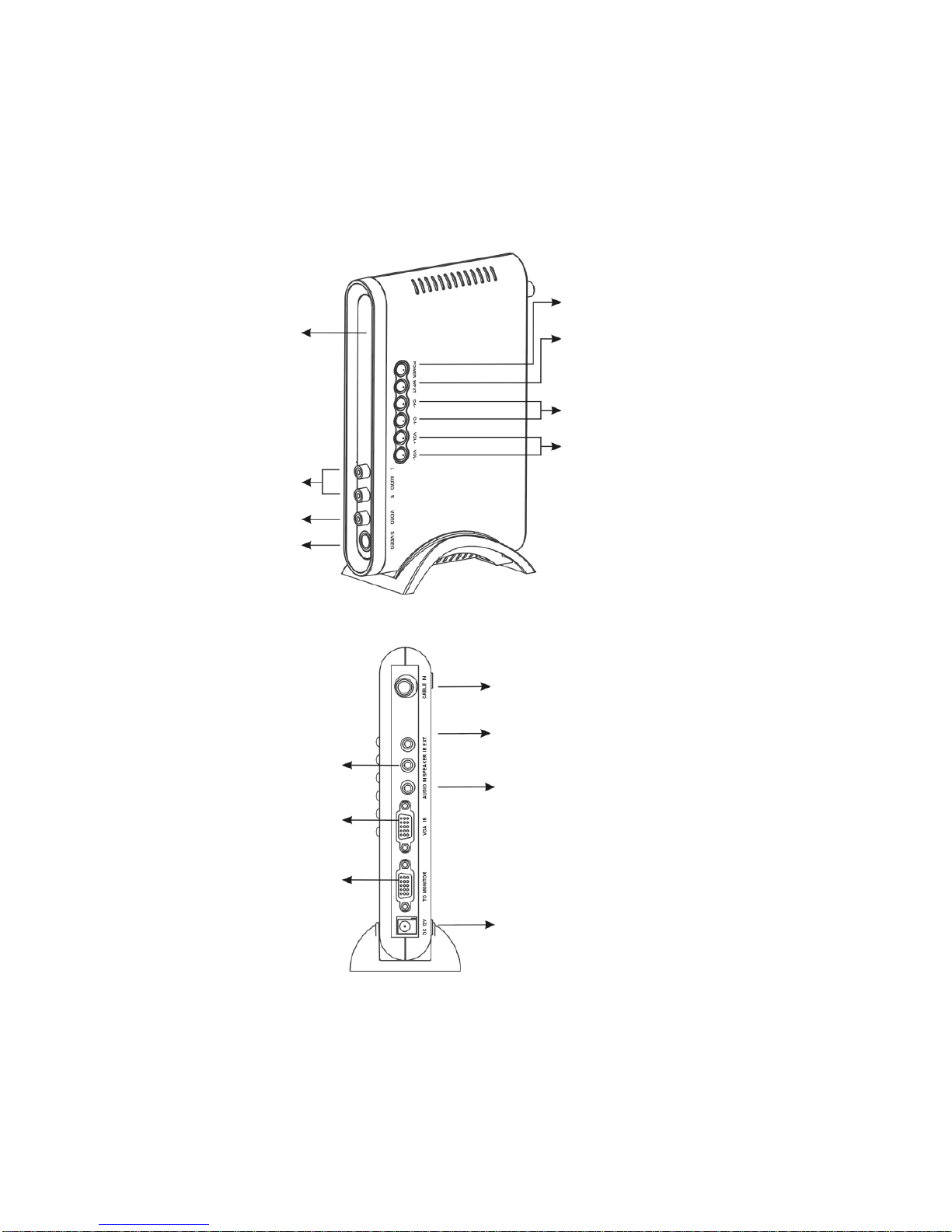
Connect the Antenna or CATV cable to the “CABLE IN” of the back
panel of the AVT-3400.
Connect the HD-15 VGA Cable from the CRT or LCD display to the
HD-15 VGA connector labeled to “TO MONITOR” on the back panel of
the AVT-3400. Connect the supplied VGA cable from the Monitor Out
port on your computer to the VGA In port on the AVT-3400.
NOTE: Fasten the HD-15 screws. It is very important to fasten the
screws. Loose connections can cause distortion of the Picture.
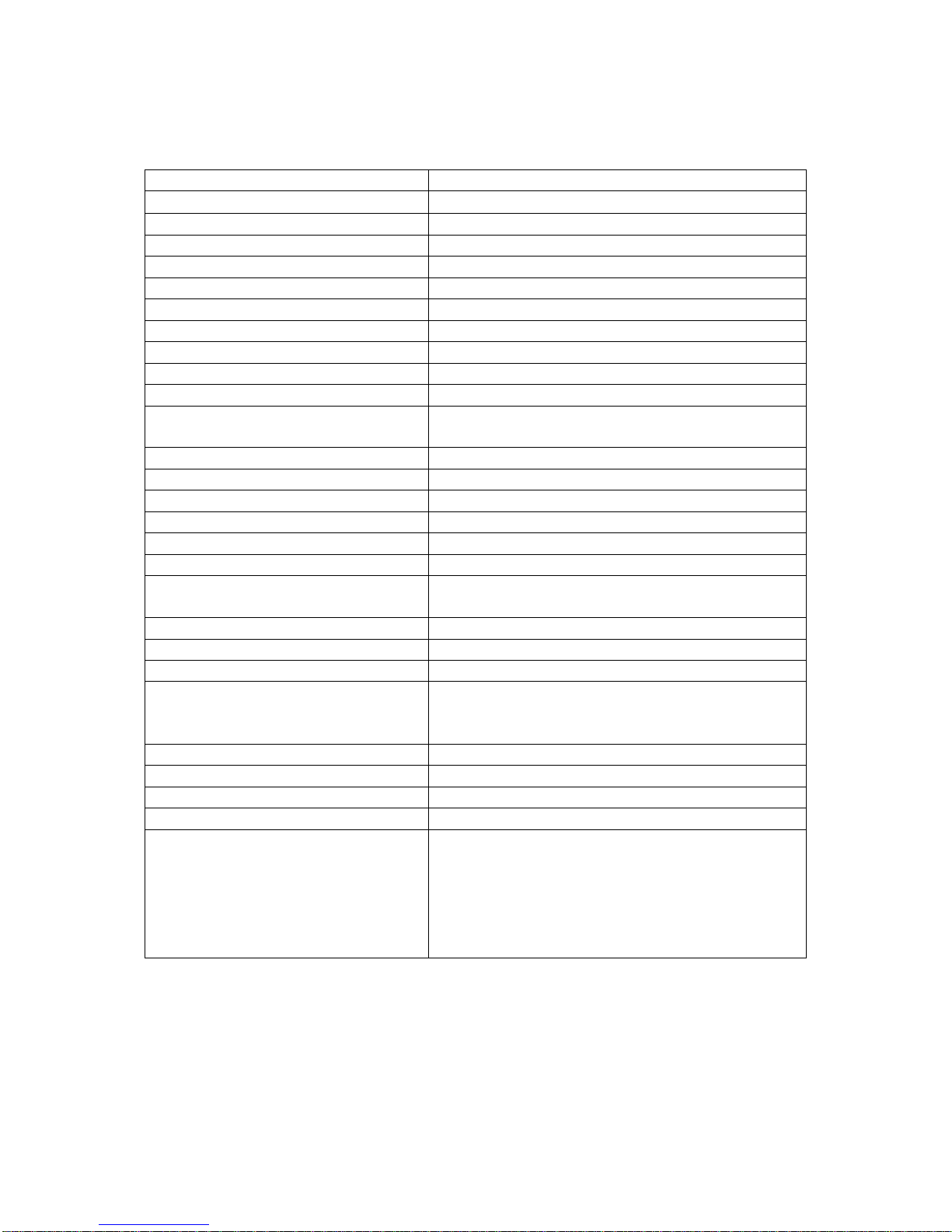
Take the 3.5mm connector from your Multimedia speaker and connect
it to “SPEAKER” on the back panel of AVT-3400.
Take the AC/DC adaptor from the shipping carton and connect the
Adaptor first to the +12 VDC input on the AVT-3400 and then to the AC
socket.
Turn on the Power to the AVT-3400 and to the CRT or LCD.
Press the Input button on the AVT-3400 to select between TV and PC
mode.
You now have the ability to route both television and computer video through the
AVT-3400.
4.3 Connecting the AVT-3400 to DVDs, VCRs, Camcorders or Games
Once you have the basic connections made as explained above, you can add
additional connectivity to external devices such as DVDs, VCRs, Camcorders or
Video Games.
Sources with RCA Type Connectors:
Using the supplied RCA cable, connect the video and audio outputs
from the device to the video and stereo audio inputs of the AVT-3400.
Turn on the power to the external device and the AVT-3400.
Using the Input button on the AVT-3400, select CVBS as the input
type.
Press the Play or Start button on the external device and an image
should appear on the previously attached monitor.
Sources using S-Video Type Connectors
Using the supplied S-Video and RCA cables, connect the video and
audio outputs from the device to the S-Video and stereo audio inputs
of the AVT-3400.
Turn on the power to the external device and the AVT-3400.