Ava RENTAL Series User manual

User Manuel
CR OR 500x500
RENTAL SERIES
User Manuel
Chapter 1
1. Features
Wellcome to Ava LED manual s helpful for you. Ths manual s ntended to provde
you wth an nstallaton nstructon. If you encounter any problems durng usage, or
f you have any suggestons, please contact us accordng to the contact nformaton
n the manual, We wll try our best to solve ths problem. We sncerely apprecate your
suggestons and mprove as soon as possble. all photos are smlar and exemplary,
The data wrtten n the catalog may derent by + - 10%
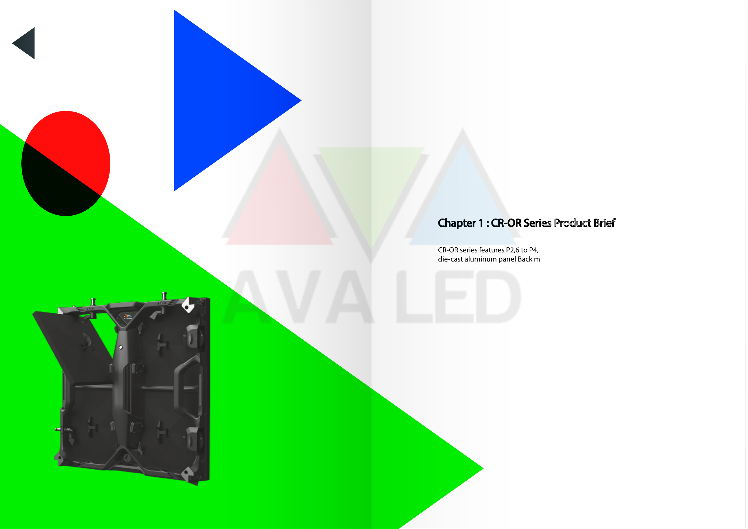
Chapter 1 : CR-OR Seres Product Bref
CR-OR seres features P2,6 to P4,81 ptch. Ultra-thn hgh-precson
de-cast alumnum panel Back mantenance. Hgh qualty.

• Super Slm & Lghtweght Desgn AV IR seres has a panel depth of only 85 mm
and less than 7 kg/panel makng t the lghtest n ts class and deal for hangng applcatons.
• Smple & Precse Installaton Support
Snap Lockng system wth Magnetsm Locatng System help one-person to nstall and
dsassemble wthn few seconds.
• Supports Varous Installaton Form-Factor
Hangng/Stackng/Floor Installaton
• Smple Product Structure
Smple Cabnet Structure
• Back Servce
2. Dmenson
Front Vew Back Panel
Chapter 2
size : 500mm
size : 500mm
size : 1.000mm
size : 70mm
7KG
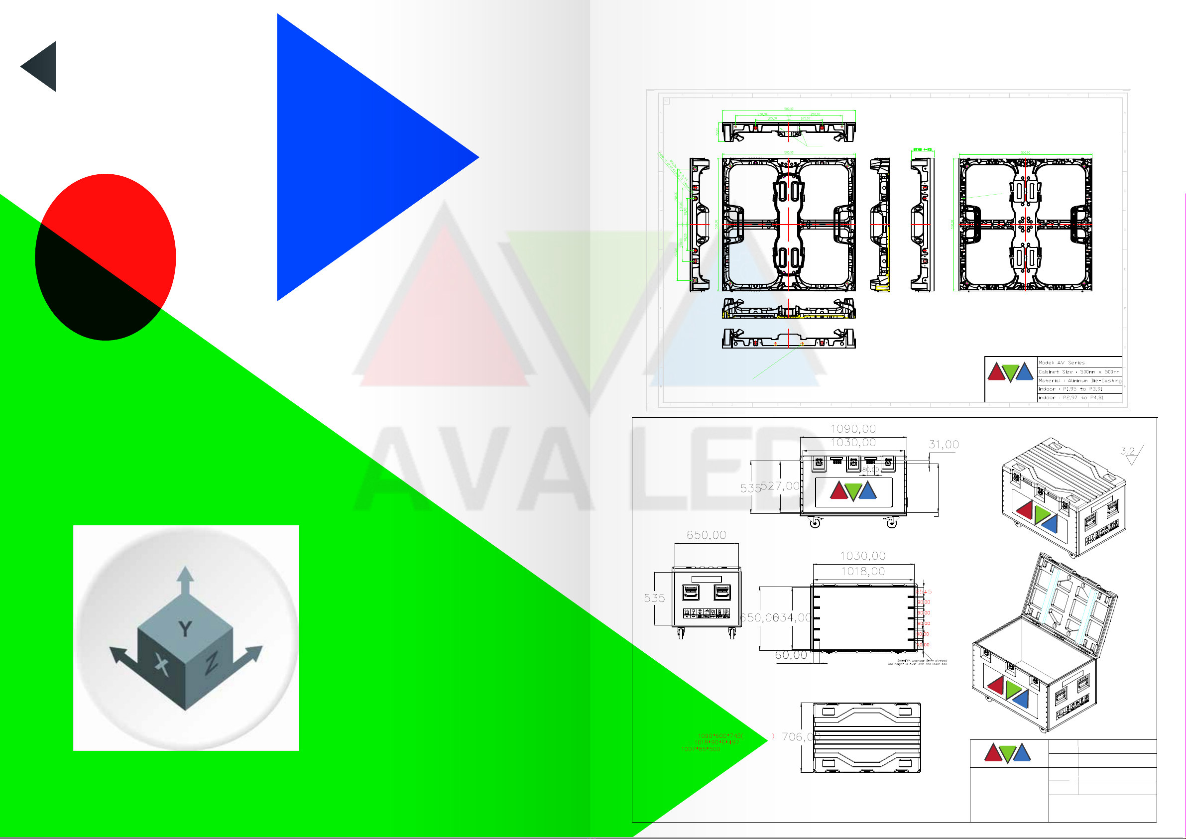
3. Dmenson
Chapter 3
!"#$%&'()*++,-.%,/%'*01,'*2
3,+4++*5678%4++*5678%9(7*%:;<=>?
3,+7()4@,(-%4++*5678
A7(@@*2%2*&@9%$55
AVA LED
!"
#$%&&'()*&'+*,,*-',*'.*,,*&
/0),**-'12&3-42*- 5 62,7'673384
92&3-42*-'2-4293'
/0.2-3,'42:3 5
;<<=;<<&&'>?@+4'A';<<=><<<&&';'@+4
4B2884')3CD2)3&3-,
>E F1'@804,2+'(82G7,'+043H'(2)3@)**(H'0-,2A+*88242*-H'630)A)3424,0-,H
@04439'I0)2*D4'JKLF',34,4E
?E M*,3N'O73'.30)2-G'+0@0+2,P'*(',73'42-G83'67338'*(',73'0I20,2*-
.*='24'&*)3',70-'>;<QRH'0-9',73',*)CD3'0(,3)'2-4,0880,2*-'24'G)30,3)',70-'#<<QR
SE T*D)'#'UV@02)'.)0B3W'.8D3'&D,3'673384'0)3'2-4,08839'0,',73'.*,,*&E'VL3I3-'0-,2A42G-4'*-'.*,7'42934WE
#E RD0)0-,33',73'2--3)'3&@,P'42:3E
;E X-4@3+2(239',*83)0-+3'42:3'Y';ZZE
[\[']^1
/[L^A_><<<
`)0-9
Z*938
a32G7, ?$'BGE
b)*9D+,4 >?@+4';<<=;<<&&'/0.2-3,
_'@+4';<<=><<<&&'/0.2-3,
4.1 Safety
Gudelnes
Chapter - 4
Ths chapter contans nformaton to prevent personal njury when nstallng the
dsplay and precautons to prevent damage to the dsplay. Before nstallng the
CR OR Seres, please ensure that you understand and follow the safety gudelnes,
safety nstructons and warnngs n ths secton.
In ths manual, the“CR OR Seres”contans the followng products from the
company: for OUTDOOR Use: CR-OR 2 ‘’P2,6’’to CR-OR 4 ‘’P4,81’’
4.1 Safety Guidelines
Personal Protection:
• Warnng: Make sure that you understand and follow all safety gudelnes, safety
nstructons, warnngs and precautons n ths manual.
• Warnng: Pay attenton to the hangng load of the ykts.
• Warnng: When nstallng the cabnet, wear a helmet to avod the rsk of personal njury.
• Warnng: Pay attenton to your fngers when nstallng the cabnets.
For Installer:
• The dsplay nstaller must be a traned, qualfed, and experenced techncan.
• The oor to be nstalled must be at and smooth.
• Console should be used n the nstallaton area
Security Tips:
• CR OR seres are n lne wth nternatonal safety standards and nformaton
technology equpment safety standards, certfed wth CE and ts parts
and components meet safety standards. Please pay attenton to safety warnng
sgns when usng to avod dangerous stuatons such as electrc shock.
SAFETY
FIRST
Warning:
• Please read the nstallaton nstructon carefully before nstallng the dsplay to
avod the rsk of njury to the user;
• Spare parts are used to replace broken parts, such as power lnes, data lnes,
Sendng boxes, etc. Parts for other manufacturer’s products are not allowed to
be used on the CR OR Seres;
• Please follow the assembly nstructons when nstallng the cabnet. If you
encounter any problems durng the nstallaton, please contact AVA LED n tme.
Product Care
• The cabnet should be kept dry and clean. It s recommended that users conduct
safety nspectons and vsual nspecton on all products regularly; checkng
whether the cables and LED lamps are damaged or not. The damaged part
needs to be repared or replaced n tme.
This manual suits for next models
2
Table of contents


