Avalon Instruments Merlino User manual

Personal Remote Observatory
“Merlino”
INSTRUCTION MANUAL
Rev. 1.0.0 May 2021
All the pictures and c ntents here included are pr perty f AVALON INSTRUMENTS. The c ntent may b t be
repr duced, published, c pied r transmitted in any way, including the internet, with ut the written permissi n f
AVALON INSTRUMENTS

2
CONTENTS
1. Merlino Observatory Description 3
2. Merlino Control System 6
2.1 User Interface Description 6
2.2 Macro Editor Description and Use 12
2.3 emperature Control and imer description and use. 15
2.3.1 emperature Control 15
2.3.2 imer functions 15
2.4 “Start Position” (HOMING) function description 18
2.5 “Polar Alignment” (POLAR) Function Description 21
2.6 Using the Monitoring Camera 22

3
1. Merlino Observatory Descripon
Merlino is the Personal Remote Observatory of Avalon-Instruments. It is designed to be totally
"user friendly", and it is current state of the art in providing you with a vastly more comfortable
and efficient use of your telescope, allowing the photographic using from remote darker sky
locations, when time is limited or weather conditions are uncertain.
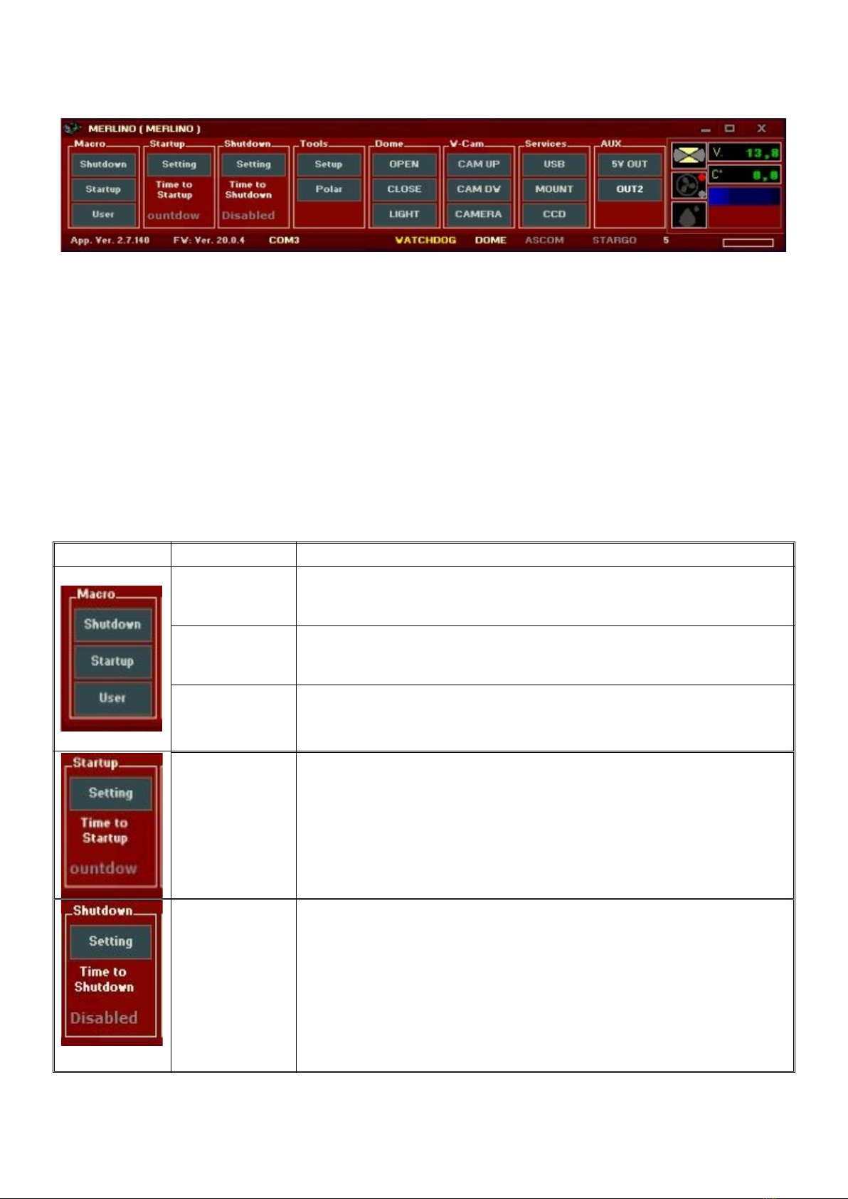
he main benefits of our design is its compactness and simplicity of use. Located inside is a PC
and a dedicated electronic board that manages an entire series of sensors for complete control
of your system, in terms of both functionality and safety. he system is controlled by a custom
made software interface that allows the Merlino to be used in a mode very similar to a typical
mobile setup. In fact, many commonly known software applications are integrated into the
system, further increasing easy of use.
hanks to its compact size, Merlino can be used in your terrace, your garden or nearly any
available space. he Merlino is entirely powered by a 12 volt, which allows it to promptly close
the session and automatically recover in case of blackout. his feature enables Merlino to be
installed in locations where there are no local power supplies, by using a solar panel energy
setup.
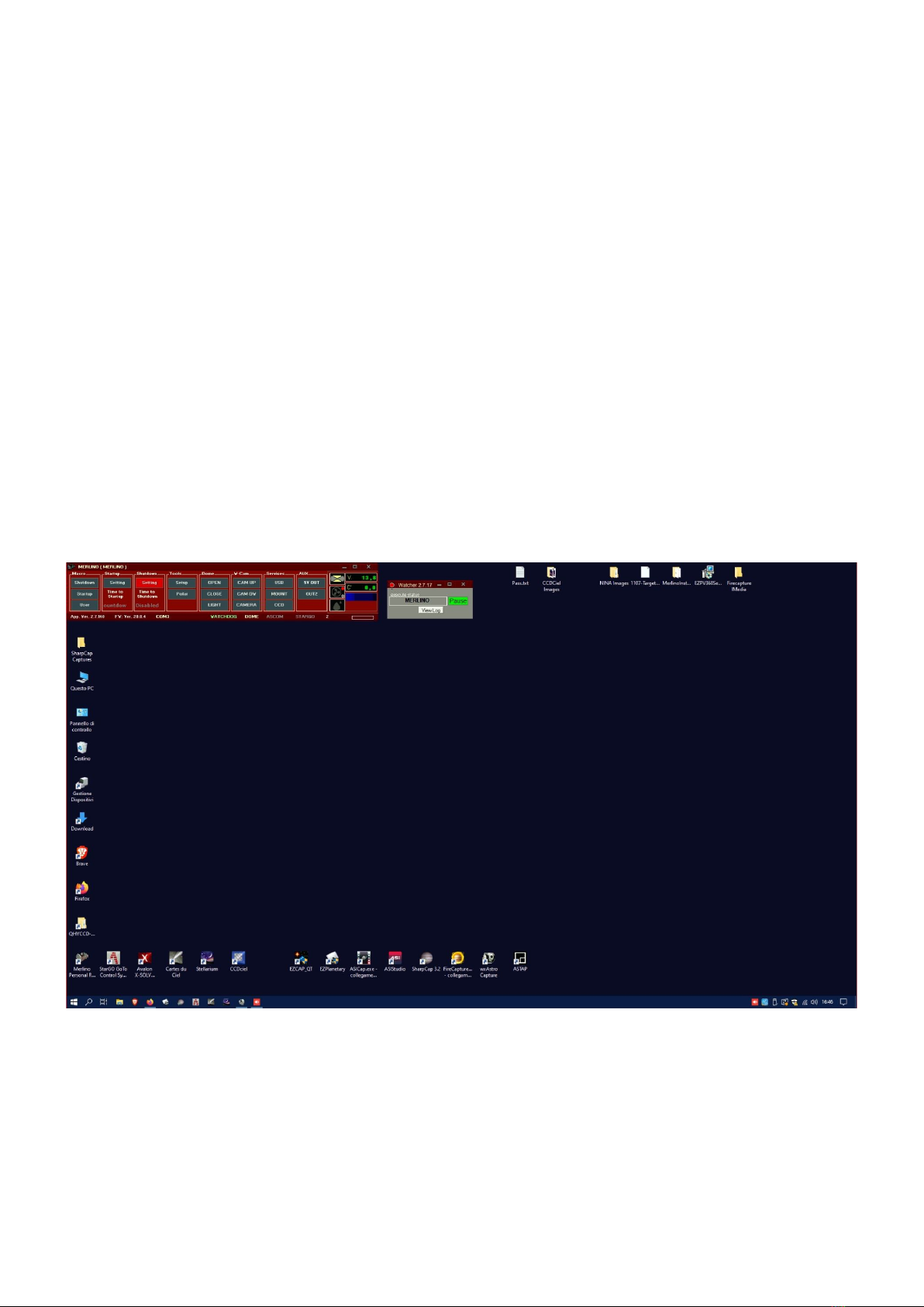
Merlino is remotely controlled via Internet. he internet connection is customer responsibility
because its availability types and reliability is strictly linked to the local internet situation. We
advise, for sake of simplicity, speed and dependability, to use a simple 4G or 3G pen drive to be
connected directly on the PC USB port (shown as an example on the figure at page 5. Other
solutions, if available, are possible, such as the direct connection to an existing ethernet
network or to an ADSL modem. In extreme cases, when Internet is not available at all, it is
possible to use Satellite modems.
he Merlino project was developed around Avalon Instruments mounts, that solves most of the
problems related to the management of a remote Observatory thanks to its special
characteristics:
1 Installation of Merlino in a terrace or backyard does not require any permits. It is shipped
already mounted inside a pallet, complete with all its features.
2he structure of the Avalon Instruments single arm mounts allows you to avoid the
annoying problem of the Meridian-Flip, thus making it possible to perform an entire
imaging session without interruption and without pointing limits near the meridian.
3 Moving mass is greatly reduced (requiring perhaps only small counterweights to balance
it), therefore reducing interior room required for slewing, as the telescope rotates virtually
on its own axis.
4he Avalon Instruments mount requires extremely little maintenance, while maintaining
consistent & excellent performance over time, thanks to the exclusive Fast Reverse
technology, designed by Avalon Instruments and using special high precision toothed
belts and pulleys, providing high reliability and durability
5Polar alignment is adjustable by the use of two stepper motors, painstakingly adapted to
allow fine polar alignment adjustments even via remote control (Optional Kit).
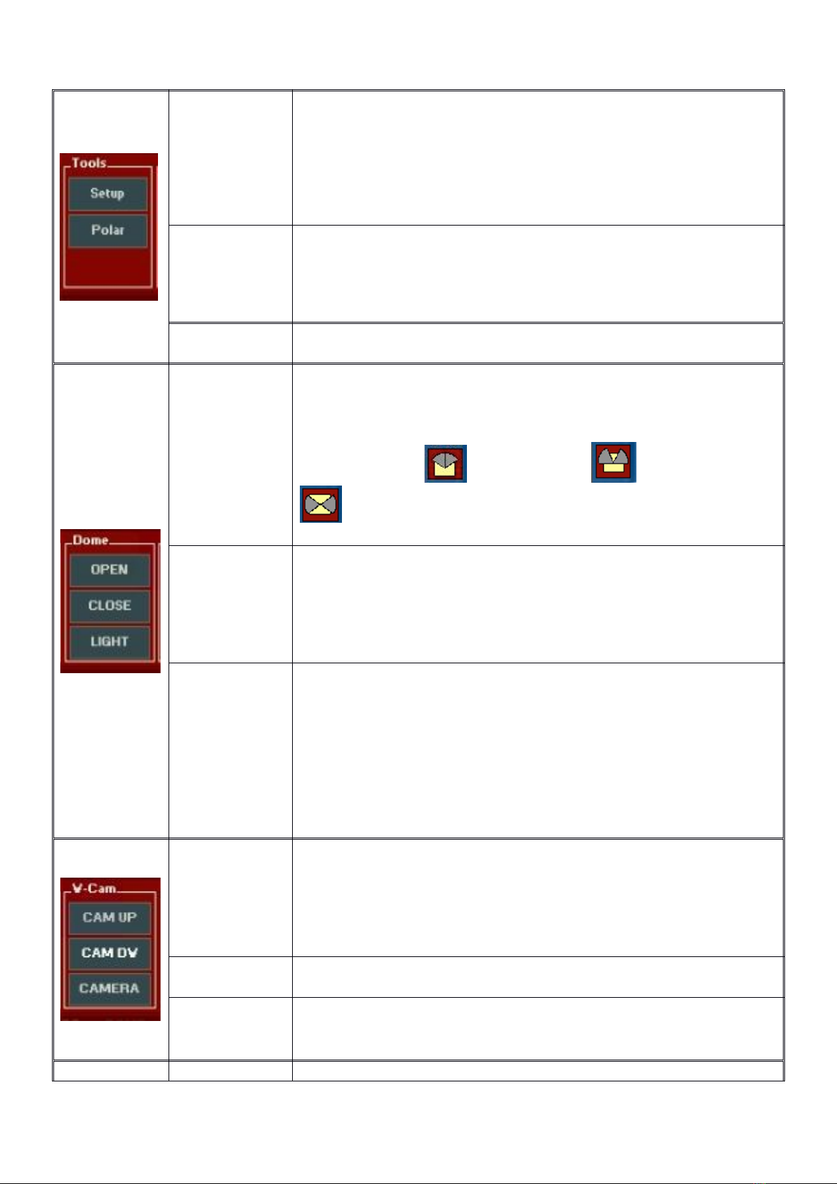
he Merlino enables you to schedule photo sessions using macros created directly by the user,
using the macro editor provided as standard equipments.

4
his allows you to automate both the beginning (startup) and closing (shutdown) of various
operations. he Merlino is able to autonomously shut down the system in case of unexpected
events or problems, thanks to the included rain sensor, thus ensuring the safety and security of
your system. It can be programmed to send you an alert via SMS. An optional alarm system
GSM allows the alert in case of an attempted at forced entry.
he following table provides the Merlino observatory specifications:
Monitored
Parameters
emperature
Rain
Battery voltage
Internet connection
otal management control software
Standard Features
inox steel bearing structure (see attachments), resin coated outside.
Motorised open/close remote controlled mechanical shutter
PC with Windows software (in English language) for the Merlino functions control
(no keyboard, no monitor)
Electronic I/O control board (diagram attached below)
Motorized webcam for internal inspection and visual sky (rain) monitoring
Rain detector.
Software management system for P.R.O. Merlino and mount
Insulated, internally wired electrical system
Power supply with 12VDC & battery charger
Instruction manual in English
Optional
Accessories
Low profile pier to support the mount
Motorized system for Polar Alignment (drivers are already included)
Remote electric Focuser, several models available

5
2. Merlino Control System
2.1 User Interface Descripon
he observatory control hardware (Merlino Control Center – MCC) is completely commanded
by the Merlino.exe software, developed inside of Avalon Instruments.
Merlino can be launched by a double click on its icon like a normal Windows program, if it
resides on the PC desktop or with a simple click if its icon is placed on the Windows
applications bar. In order to optimize the observatory remote control, it is advised to launch
Merlino.exe contextually to the start of Windows and always leave it opened and active. Its re-
launch will only become necessary in case of unexpected program crash. Remember that, in
case of launch, the program requires the administrator privileges in order to correctly work.
At the operating system start, besides Merlino.exe, also the monitoring program Watcher.exe
that has the task to monitor the correct operation of the Merlino.exe and the MyWlan.exe (if
needed) application will be contextually launched. he latter controls the Internet connection.
herefore the aspect of the desktop after the access will be similar to that shown in Figure 1.
Fig. 1 – PC Desktop after a fresh computer Start
his figure shows the Merlino.exe main interface on top left and the interface of the other two
support applications on top right.
he Merlino.exe GUI is reported in the following Figure 2.

6
Fig. 2 - Merlino.exe GUI
he interface is subdivided in several functions, grouped in homogenous way, that allow the
execution of all the possible operations on the observatory. On the right side are placed the
important pieces of information related to the power supply battery voltage, the environmental
temperature inside the observatory cabinet, besides the icons that describes to the state of
closing or opening of the observatory and the rain information.
he keys inside the function matrix represent the switches of activation of the single Merlino
hardware operations. If the keys are of lighted red color it means that the associated functions
are active (ON), if they are of dark red color their states are OFF. Some keys (as the keys
OPEN and CLOSE) activate and change their color only while they are pressed and return dark
to their release, indicating that their function is active only when they are pressed (they act as
push buttons). he other keys, once pressed, change status like simple ON/OFF switches.
he table that follows describes in detail the single commands, subdivided by functions.
Funzi ne Operazi ne Descrizi ne dell’ perazi ne
Shutd wn
he Shutdown key starts the macro that sequentially executes
the deactivation of all the peripheral and the applications in
execution in order to put the observatory in safety conditions.
Startup
his key starts the execution of the Startup macro for the
execution of all the operations necessary to put the observatory
in a fully operating status.
User
It opens the windows to customize the mentioned macros
adding or delating operation lines as required by the user. he
macros will be explained in detail in section 2.2.
Startup
SETTING
his is the key to calculate the time to observatory startup.
It can be usefull, if a software for the automatization of the
photographic shooting is used, to determine when startup the
observatory.
Even this function is described in section 2,3.
Shutd wn
SETTING
his is the key for the calculation of the photographic
session duration.
he pressure of Shutdown “SE ING” provokes the
appearance of a setup window through which it is possible
to define the timing of the operations before the automatic
shutdown of the observatory starts.
he use of such function is described in detail in the
section 2.3.

7
HOMING
he key HOMING is a very important as it will allow to bring the
telescope in the “Home” starting position with extreme
precision, making the objects search during the photographic
session very precise. Its use will be described in detail in
section 2.4.
POLAR
he key POLAR opens the windows related to the telescope
movement in the horizontal (Azimuth) and vertical (Height)
directions, in order to optimize the mount polar alignment. he
use of the “POLAR ALIGNMEN ” function will be described in
section 2.5.
Setup his key allows the access to a setup panel allowing to insert
limiting temperatures
OPEN
Such button activate the observatory roof opening system
motor. he roof opens until the button is pressed. It stops to
open when the button is released or when roof reaches the
complete opening.
he roof closing , partial opening and full opening
conditions are graphically indicated by the appropriate
icon. he opening of the roof is inhibited in case of rain.
CLOSE
his is the inverse of the previous function and it is activated in
the same way holding pressed the button in order to close the
observatory until complete closing of the roof occurs. he
indications of position of this are the same already described.
he system of Closing/Opening is protect by safety clutches.
LIGHT
Switch of the lighting system inside the observatory. It is of On/
Off type and is initially in Off position with the internal light
turned off. Pressing it once it turn on the internal lights.
Pressing it a second time the lights are turned off. In the course
of a photographic session the lights should remain turned off in
order to avoid reflected parasites lights in the telescope. It is
useful switch the lights on in order to monitor the observatory
status or the telescope position and during the realignement
operations.
CAM UP
It is a button that moves the monitoring CCD towards the high
until is held pressed. his allows to move its FOV at will. he
maximum reacheable position is the vertical one, which is
useful for the observation of the sky to estimate of the
cloudiness conditions.
CAM DW It has the inverse function. It moves the monitoring CCD toward
the bottom and the maximum reachable position is horizontal.
CAMERA By clicking on this button, the internal camera will switch on and
start to show to the user the observaory internal view.

8
USB
his switch activates all the observatory USB devices (Mount,
main CCD, guiding CCD, internal Webcam, Allsky cam, etc). It
must be in ON position (closed) for monitoring CCD that is USB
driven
StarGO
StarGO is the key that closes the mount electric power supply
circuit. It is of On/Off type and initially it is in Off position.
Pressing it, a window of warning is opened asking to confirm
the action. Pressing OK in such window the mount is powered
and the button assumes the red color. Pressing it a second time
the power circuit is opened and the mount is turned off. he
button returns dark. Such button launches also the software of
the StarGO mount management.
CCD
CCD is the key that closes the mount electric power supply
circuit. It is of On/Off type and initially it is in Off position.
Pressing it, a window of warning is opened asking to confirm
the action. Pressing OK in such window the mount is powered
and the button assumes the red color. Pressing it a second time
the power circuit is opened and the CCD is turned off.
5V OUT Auxiliary switch to turn On/Off additional components
OUT2 Auxiliary switch to turn On/Off additional components
As already mentioned, some of the described commands demand a confirmation before they
are executed. he confirmation assumes the aspect of the classic window in which to accept or
reject the execution:
MOUNT
CCD

9
USB
Beneath of the described function frames a series of relative information to the state of the
Merlino software is supplied.
In particular the first three pieces of information are relative to the state of the installed software,
that is: the version of the application, the version of the Firmware and the COM port to which
Merlino is connected. In case of missing connection, instead of the indication the used port an
error condition is given.
he three successive indications are relative to the state of the Watchdog (redundant safety
control), of Avalon ASCOM device driver and, the last, the status of the StarGO software. When
they are colored in yellow they are active and the relative software is operating.
Figure 3 shows the part of the main Merlino panel containing some environmental and
functional information:
Fig. 3 Aux and enviromental informations
he three icons on the left indicate respectively:
the observatory conditions as previously described
he activation of the electronic panel cooling fan
the activation of the rain alarm (the two droplets turn blue) and the consequent activation
of the protection function, causing the immediate roof closure and the prevention of
successive re-openings if the rain conditions persist.
he rain intervals and its intensity are shown in the last blueish rectangle to the bottom right.
Clicking on this rectangle the Rainfall Monitor window with more detailed information will
appear:

10
On the right of figure 3, the first two windows indicate the service battery voltage and the
temperature inside the electronic cabinet. Clicking over the C° simbol the measurement unit will
change to F° (and vice versa).

11
2.2 Macro Editor Descripon and Use
he USER button, as mentioned in the previous section, allows the access to the command
editor to prepare command sequences. Pressing the button the MACRO window opens
showing the last macro developed (in this case a demo) as reported in the below left figure. he
buttons Start and Stop allow the launch or to end the execution of the macro. Pressing the Edit
button the MACRO window extends in order to show the column of the editing commands, as it
is seen in the figure to the right:
he check box columns to the left of the command list indicates if the execution must be
executed or not. his feature allows to skip some commands in particular case, for example
during testing.
he leftmost colums delay contains the extimated time needed (in seconds) to complete the
command execution. his value is very important for those commands requiring to be
completed before the next one is started, especially for the commands that, for their nature,
require a longer time to be completed, such as mount parking and roof opening/closing. By
choosing a right value the risk to perform a command before the previos is completed is
avoided.
o modify a command line it is sufficient to click it and then press EDI button to the left (or
double clicking on the command line itself) he Command Editor window will pop up containing
all available commands among which to select the needed one, using the lateral sliding bar.
o add further commands to the macro list is sufficient to press the ADD key and choose the
various commad up to the macro completion.

12
o move up and down the existing command of the macro list is sufficient to select the
command and using the two up and down arrows available in the editor window.
he complete list of the available commands in the system is the following:
WEB CAMERA MOVE UP (CAM UP)
WEB CAM MOVE DOWN (Cam DOWN)
USER RELAY 3 ON
USER RELAY 3 OFF
USER RELAY 2 ON (OUT 2)
USER RELAY 2 OFF (OUT 2)
USER RELAY 1 ON (5V OUT)
USER RELAY 1 OFF (5V OUT)
TURN ON USB PERIPHERALS (USB)
TURN ON MOUNT (MOUNT)
TURN ON INTERNAL LIGHT (In .Ligh )
TURN ON FLAT PANEL (FLAT)
TURN ON DEW HEATER (DEW)
TURN ON CCD (CCD)
TURN OFF MOUNT (MOUNT)
TURN OFF INTERNAL LIGHT (In .Ligh )
TURN OFF FLAT PANEL (FLAT)
TURN OFF DEW HEATER (DEW)
TURN OFF CCD (CCD)
START WEBCAM (CAMERA)
STARGO COMMAND
SET PARKIMETER IN MINUTES
RUN MACRO
RUN
REMOVES SOLAR FILTER
RELOCATING SOLAR FILTER
PROGRAM START
OPEN PARKTIMER (TIMER)
OPEN OBSERVATORY (OPEN)
MAKE A PAUSE
KILL PROGRAM
EXTERNAL CONTROLS
END PROCEDURE
CLOSE WEBCAM (CAMERA)
CLOSE THIS PROGRAM
CLOSE PARK TIMER
CLOSE OBSERVATORY (CLOSE)
CHECKED OBSERVATORY CLOSE

13
Note that two of the listed commands (S AR PROGRAM and KILL PROGRAM) require the
access to an external program. When one of these commands is used in the macro, a classical
Windows choosing window is opened to allow to choose the needed program.
As an example, we will build a macro to monitor the observatory using the available monitoring
CCD without activating the other observatory components. he following is the operation
sequence to perform:
Roof opening
USB activation
Start the default monitoring CCD program
60 seconds pause to observe the sky
End the default monitoring CCD program
USB deactivation
Roof closure.
By inserting the commands to execute these operation we will obtaing the following:
Such figure shows the Macro window during the execution of the commands. Note that the
commands already executed and those under execution are totally or partially colored in green.
he bypassed commands (check the box unselected) remain of the original color. he image
has been taken to the end of CLOSE WEBCAM command execution.
he following table describes the function of all the editing buttons on the right of the MACRO
editing window:
Save Save the current macro. It calls the file saving Windows function..
DEL Delete the currently highlighted command
ADD Add a new command line. It calls the opening of the command list windows allowing the
selection of the wanted command.
EDI Modify the selected command. It calls the opening of the command list windows
allowing the selection of the command to replace the existing one.
Run his Execute the current macro.

14
2.3 emperature Control and imer descripon and use.
2.3.1 emperature Control
Merlino observatory is provided of a cooling fan to keep the temperature inside the electronic
control cabinet below set limits. Optionally, for the use in cold countries, an optional electrical
heater may be provided to increase the internal temperature when needed. Both the cooling fan
end the heater are managed by the control panel via the Setup window, which is activable
pressing the Setup key in the ool panel of the main GUI:
he High and Low emperature setpoint are inserted on the right and the Cooling and / or
heating functions may be activated by checking the checkboxes on the left.
he checking of the two function’s operability is possible to click on the “ ” keys near the
respective check boxes.
Hide key will close the Setup window.
2.3.2 imer funcons
he timer functions have a fundamental function in the management of a remote observatory.
hey allow to define the moment of observatory opening or closing by automatically executing
the Startup and Shutdown macros. Merlino software supplies the two functions of closing and
opening using independent software keys.
At the software start, for safety reasons, the Shutdown imer is automatically activated with
predetermined amount of second at the closure, usually an hour or 3600 seconds, in order to
permit a consistent period of operations (including the formulation of a more suitable operation
time) before the safety closing. his timer is extremely useful because it automatically executes
the Shutdown of the system also in case of loss of the Internet connection.
herefore, quickly after the Startup, it is advisable to set up the operation time sufficient for
carrying out the intended activities in order to avoid an unintentional closing of the observatory.
In order to do this it is necessary to press the SE ING key in the Shutdown frame. Such
operation will cause, on the left of the Merlino software interface, the opening of a black window
for the calculation of the times, as follows:

15
he use of such window is intuitive: insert the number of the exposures and their individual
duration in the opportune fields. he total time, expressed in second, will be calculated and will
appear in the otal Seconds field. It is advisable to increase this value of some hundred
seconds in order to take into consideration the dead times between the images and those
between the other needed operations to be sure to not execute the Shutdown before the
session is finished. he Hide key hides the calculation window while the Start/Stop starts the
timer with the calculated time.
he passing of the time in second, between the set up time and the programmed shutdown is
shown in yellow in the Shutdown frame:
he observatory shutdown can be automatically caused, as well as the reaching of the
time limit also by the occurring of some events making useless to continue the
observatory operations such as the sky clouding and the consequent failure of the
autoguide system.
Analogously the Startup timer is activated by pressing SE ING key of Startup frame and also
in such case it will opened, to the left of the Merlino interface, a black window to setup the start
time. he Startup timer is useful for the programming of a session starting at a determined date
and time.
he information to introduce in such window are somewhat different from those used in
precedence. he date shall in fact be inserted (YYYY– MM – DD) as well the hour (H – M).
Moreover, in last the two fields, the session duration can also be inserted.
With Hide the window is closed and with Start–S OP the timer for the Startup is primed. he
hours, minutes and seconds to the observatory startup execution will appear in yellow in the
Startup frame.

16
.

17
2.4 “Start Posion” (HOMING) funcon descripon
In order to obtain a better pointing precision it is necessary that the alignment operations,
described in detail in the StarGO manual, are executed beginning from a Home position as
much as possible close to the ideal position, i.e. with the telescope axis aiming exactly to the
North Pole. Even if this operation is easily executable operating the telescope locally, just
aligning the axis reference notches to those printed in the mount, it becomes more difficult when
it is executed in remote.
Being this the first operation that is carried out just after the observatory startup, it will be start
with the telescope parked (i.e. in Park position) as defined during the observatory setup
operations.
he pressure of the HOMING button in the ools frame will start the homonymous operation
and, if not already on, a warning window will be opened which asks the connection of the
peripherals interested to the operation to carry out.
Pressing Ok a second warning window will open asking the startup of the ASCOM driver (if not
already running).

18
Pressing the UNPARK key on the StarGO application the mount will be unparked and the
moving commands will appear and become active in the StarGO.

19
2.5 “Polar Alignment” (POLAR) Funcon Descripon
hanks to the optional Motorized Polar Alignment kit available on the M-zero OBS, M-uno and
M-tre mounts, it is also possible to carry out a remote and precise Polar Alignment.
he motors can be easily controlled with the special Polar Alignment tool that comes with the
StarGo software.
he tool can be enabled by clicking on the corresponding radio button available in the AUX tab.
hrough these two windows it will be possible to move the mount in the two axes towards ES /
WES or HIGH/LOW direction in continuous using the appropriate keys. he key S OP will
stop the movement. In case is needed to move the mount of a predetermined amount (0.1, 1
and 10) of arcmin in the two directions, the appropriate keys can be used. Finally it is also
possible to carry out goto movement using the GO O keys and the arcmin value inserted in the
fields on the left of the keys.

20
he Polar Alignment tool, if used in combination with Precise Polar Alignment external devices,
using they’re software to calculate the alt-azimuthal offset of the polar axis from the celestial
North Pole, allow an easy and precise remote Polar Alignment operation.
Once the device will notice the Alt/Az error, it will be really easy to the user to compensate it
“manually” with the Polar Alignment tool commands.
After the correction will be performed, another plate solve can be taken until the errors become
accettable.
Furthermore, thanks to the Realign Absolute Position feature, in case of Parking at the end of
the session, this offset can be stored in the system memory and will be saved for the next use
even after a system shut down and power off.
Table of contents
Popular Science Education Product manuals by other brands

PASCO
PASCO Spark SLS user guide

Utopia 360
Utopia 360 EDUCATION 4D+ Space Exploration user manual

laerdal
laerdal Neonatal Intubation Trainer Directions for use

Life form
Life form LF03699U instruction manual

Elecrow
Elecrow CrowBot BOLT Assembly instruction

Thames & Kosmos
Thames & Kosmos Glow-in-the-Dark Science Lab manual