Avantco Snow Blower 1100 User manual

Snow Blower 2013 1
Avant Tecno Oy 2013 Copyright all rights reserved
Please read this manual carefully before using the equipment, and follow all
instructions.
Keep this manual for later reference.
Operator’s
Operator’sOperator’s
Operator’s
manual for Attachment
manual for Attachmentmanual for Attachment
manual for Attachment
S
Sn
no
ow
w
B
Bl
lo
ow
we
er
r
1
11
10
00
0
S
Sn
no
ow
w
B
Bl
lo
ow
we
er
r
1
14
40
00
0
Product number: for 200-series loaders: A35940
For 300-700-series loaders: A35870
A35847

Snow Blower 2013 1
Avant Tecno Oy 2013 Copyright all rights reserved

Snow Blower 2013 1
Avant Tecno Oy 2013 Copyright all rights reserved
CONTENTS
1. Foreword...............................................................................................................................4
2. Designed purpose of use ......................................................................................................5
3. Safety instructions for using the snow blower........................................................................5
4. Technical specifications ........................................................................................................8
4.1. Safety labels and main components of the Snow Blower................................................................
8
5. Assembly of the snow blower..............................................................................................10
5.1. Attaching the snow blower to the loader.......................................................................................
10
5.2. Connecting and disconnecting hydraulic fittings...........................................................................
11
5.3. Electrical connection ...................................................................................................................
13
5.4. Uncoupling and storage of the snow blower.................................................................................
13
6. Instructions for use..............................................................................................................14
6.1. Checks before use ......................................................................................................................
14
6.2. Operating the snow blower..........................................................................................................
15
6.2.1.Discharge chute rotation..........................................................................................................
16
6.2.2.Scraper plate and skids...........................................................................................................
16
6.2.3.Removing a blockage..............................................................................................................
17
7. Maintenance and servicing..................................................................................................17
7.1. Checking hydraulic components..................................................................................................
18
7.2. Cleaning the snow blower............................................................................................................
18
7.3. Feed auger and thrower fan ........................................................................................................
19
7.4. Discharge chute rotation..............................................................................................................
19
8. Warranty terms....................................................................................................................19
Appendix: EC Declaration of Conformity

4(12)
1. Foreword
Avant Tecno Oy would like to thank you for your purchase of this AVANT attachment. It has been designed
and manufactured on the basis of years of experience and product development. By familiarising yourself
with this manual and following the instructions, you ascertain your safety and ensure the reliable operation
and long service life of the equipment. Read the instructions carefully before starting to use the equipment or
performing maintenance.
The purpose of this manual is to help you to:
■operate the equipment in a safe and efficient manner
■observe and prevent any hazardous situations
■keep the equipment intact and ensure a long service life
The following warning symbols are used throughout this manual to indicate factors that must be taken into
account to reduce the risk of personal injury or damage to property:
Notice:
This notice symbol indicates information about the correct operation and
maintenance of the equipment.
Failure to observe the instructions accompanying the symbol can lead to
equipment breakdown or other property damage.
With these instructions, even an inexperienced user can use the attachment and loader safely. The manual
includes important instructions for experienced AVANT operators as well. Ensure that all persons using the
loader have received proper guidance and familiarised themselves with the manual of the loader and
attachment and all safety instructions before using the equipment. Using the equipment for other purposes or
use in any other way than described in this manual is prohibited. Keep this manual at hand throughout the
service life of the equipment. If you sell or transfer the equipment, be sure to hand over this manual to the
new owner. If the manual is lost or damaged, you can request a new one from the retailer or manufacturer.
Original instructions.
In addition to the safety instructions included in this manual, you must observe all occupational safety
regulations, local laws and other regulations concerning the use of the equipment. Particularly the
regulations concerning the use of the equipment on public road areas must be observed. We reserve the
right to change the contents of the manual without notification.
Warning:
This safety symbol refers to important safety information in this manual. It
warns of an immediate hazard that could cause serious personal injury or
property damage.
Read the warning text accompanying the symbol carefully and ensure that
other operators are also familiar with the warnings, since personal safety is at
stake.

5(12)
2. Designed purpose of use
The AVANT Snow Blowers are attachments designed and manufactured for use with AVANT multi purpose
loader models that are listed in Table 1. The Snow Blower is especially suitable for use when it is preferred
to spread snow evenly to the sides of the area instead of piling it up. The two-phase snow blower is suitable
also for professional use, and it is equipped with a powerful hydraulic system with two separate hydraulic
motors, guaranteeing efficient operation even when handling wet and heavy snow.
As standard, the blower chute can be turned electrically by 260 degrees directly from the driver’s seat. The
wide adjustment range of the manual throwing height control makes it possible to control the ejection of
snow precisely as needed, either as to pile snow directly to the side of the drive path, or to spread evenly far
away. As an option, electric throwing height adjustment is also available, which can be operated only with
the electric attachment control switch pack, which is available as an option for 400-700 series loaders. In
heavy snow conditions the optional snow wall cutter extensions help to achieve neat and precise snow
removal and they can also be used to increase the working width.
The attachments have been designed to require as little maintenance as possible. The operator can perform
regular maintenance tasks. However, all repair work can’t be performed by the operator, and demanding
repair and maintenance operations must be left for professional service technicians. All maintenance work
must be done using proper safety equipment. Spare parts must be similar to original specifications, which
can be ensured by using only original Avant spare parts.
Familiarise yourself with the manual's instructions regarding service and maintenance. Please contact your
AVANT retailer if you have additional questions about the operation or maintenance of the equipment, or if
you require spare parts or maintenance services.
Table 1 – Snow Blower 1100 A35870 / A35940 and 1400 A35847 compatibility with Avant loaders
Snow Blower 1100
A35870 A35940 Snow Blower 1400
A35847
745, 750, R35, 635,
640 -•
••
•
630 (•)
(•)(•)
(•) (•)
(•)(•)
(•)
R28, 528, 525LPG,
419, 420, 220 •
••
•-
218, 320 - -
3. Safety instructions for using the snow blower
Please bear in mind that safety is the result of several factors. The loader-attachment combination is highly
powerful, and improper or careless use may cause serious personal injury or property damage. Due to this,
you should carefully familiarise yourself with the manuals of both the loader and the attachment before
starting operation. Do not use the attachment if you have not familiarised yourself with its operation and the
related hazards.
When using with models marked with
(
((
(•)
))
), full performance may not be
achieved. For compatibility with a
model not shown in table, contact your
Avant retailer.

6(12)
Misuse, careless use, or using an attachment that is in bad condition, may cause
serious injuries. Familiarise yourself with the controls of the loader and coupling and
safe operation of the attachment at a safe area. Become familiar especially with how
to stop the equipment in a safe manner. Read the following safety precautions
carefully.
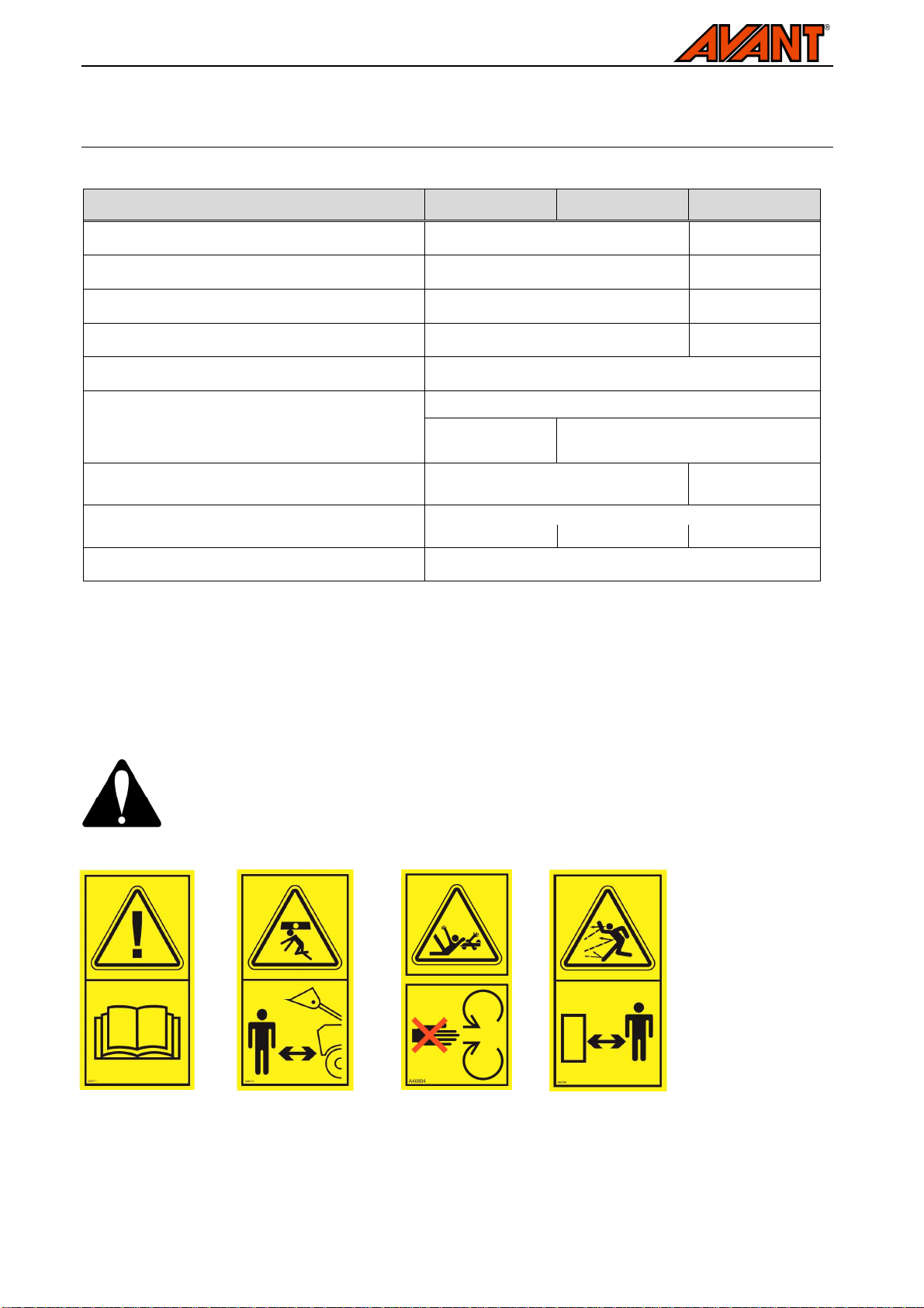
Read all safety instructions carefully before handling the attachment
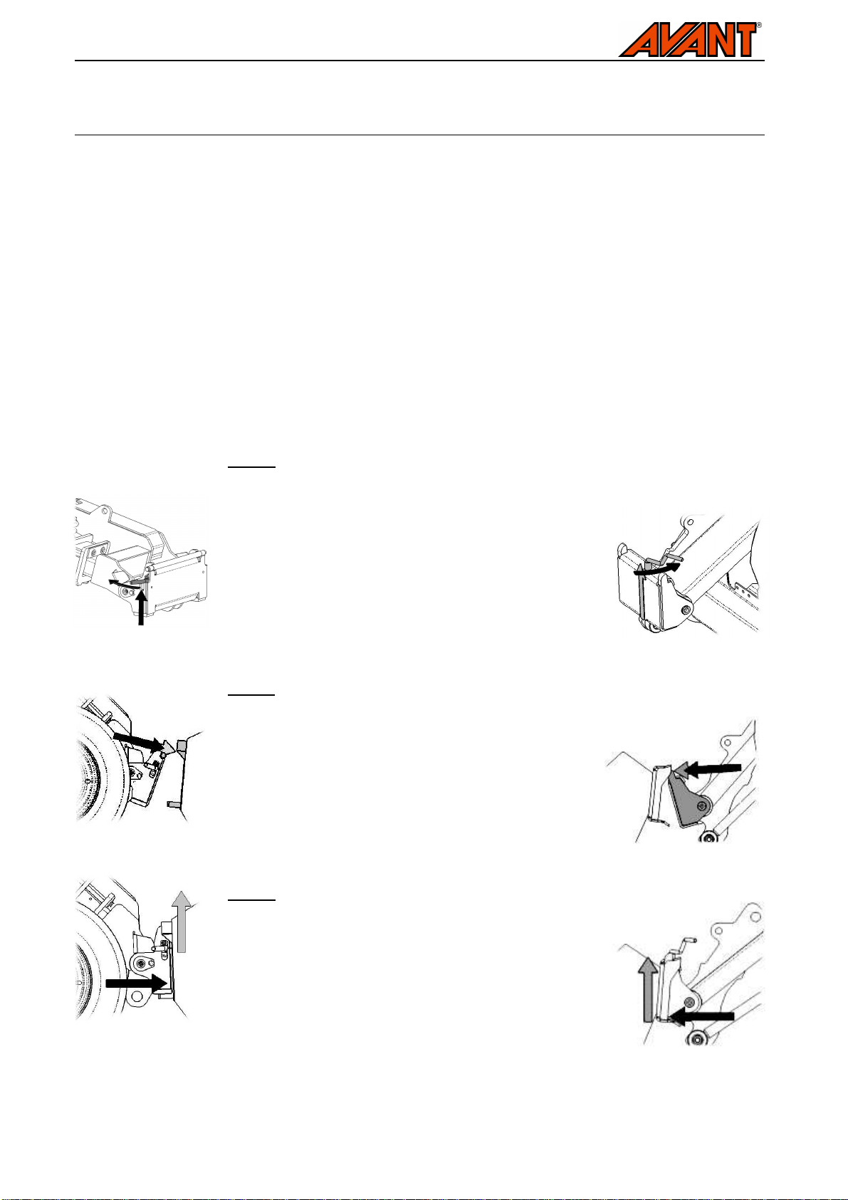
•When attaching the attachment to the loader, ensure that the locking pins of
the loader's quick attach plate are positively in the lower position and that
they have locked the attachment to the loader.
•The Snow Blower is to be used by one operator at a time. Do not go near a
running attachment or allow others to approach the area where the machine is in
operation.
•Never leave the driver’s seat when the snow blower is running or when the
auxiliary hydraulics control lever of the loader is locked on and keep a safety
distance of at least two metres between activated snow blower and any person
in vicinity. Keep hands and feet away from moving parts. Beware of entanglement
and severing hazards and possible debris thrown by the blower.
•Lower the attachment firmly on the ground before leaving the driver’s seat. Make
sure that the attachment is properly supported during maintenance or
inspections. Do not leave the driver’s seat when the loader boom is lifted. Going
under a raised attachment or loader boom is dangerous, as the boom may lower
due to loss of stability, mechanical fault or by other person operating the controls
of the loader. Follow safe stopping procedure before any maintenance or
adjustments. Before clearing blockages, the attachment must always be stopped
following safe stopping procedure, to prevent unintended starting of the blower
once the blockage has been cleared.
•Pay attention to the surroundings and any other persons and machines moving in
the vicinity. Pay attention to the contours of the terrain as well as other hazards,
such as loose rocks, or branches and trees that reach the driver's area.
•Keep in mind that the blower will throw snow and any other objects entering the
blower at high speed. Do not operate the snow blower, if the discharge chute is
directed towards other persons or fragile objects. Make sure that the rotation of
discharge chute works smoothly, and that the discharge chute protector and
throwing height deflectors are securely fastened. Lock the manual throwing
height adjustment securely.
•Make sure to use only an attachment that is in good condition. Perform daily
inspections and read the instructions regarding service and maintenance. Never
operate the attachment if the hydraulic systems of both the attachment and the
loader are not completely intact. Check the condition of the blower rotor regularly.
•Do not modify the attachment in a manner that would affect its safety.
•Make sure that the loader is equipped with necessary safety equipment, and that
they are in order. Seat belt must be used. If there are specific risks at the
operating area, appropriate safety equipment must be used.
•Also read the safety instructions of the loader from the operator’s manual of the
loader. Get familiar with the controls of the loader and how to drive it safely, and
also note the effect slippery surfaces to the handling charasteristics of the loader.

7(12)
Note that the blower may throw sand or other
objects found in the operating area up to 30
metres away at high speed. Always keep a
safety distance of at least two metres between
the snow blower and other persons. Do not
allow others at the danger areas of the blower
and stop the snow blower immediately, if there
are others in the direction of snow throwing.
Near the snow blower the hazards of entanglement and severing are present. The
snow blower must be stopped following the safe stopping procedure before going
near it. Never put your hand inside the discharge chute or the auger; always use a
brush or other suitable medium. Removing the discharge chute guard is allowed only
when removing blockages. The guard must be securely locked in its place
immediately after clearing the blockage.
Safe stopping of the equipment, before going near the snow blower
Always stop the snow blower following safe stopping procedure before going near
the attachment. Never go under a raised loader boom or the attachment. Note that
the loader boom can move down even if the engine of the loader is turned off. Safe
stopping procedure:
•Stop the attachment and the loader.
•Lower the boom and the attachment on the ground.
•Shut down the loader engine and lock the parking brake.
•Release residual pressure from the hydraulic system.
•Prevent starting of the machine, remove key from ignition.
Remember to wear proper protective clothing:
•The noise level in the driver's seat exceeds 85 dB(A). Wear hearing protection while
working with the loader.
•The use of safety boots is recommended while working with the loader.
•Wear protective gloves. When handling hydraulic hoses or components, wear also
safety goggles.

8(12)
4. Technical specifications
Table 2 – Snow blower specifications
Product number: A35940 A35847 A35870
Working width: 1100 mm 1400 mm
Working width with optional snow wall cutters: 1200 mm 1500 mm
Total width: 1281 mm 1 581 mm
Weight: 225 kg 255 kg
Electric discharge chute rotation: Standard equipment, 260º
snow wall cutter extensions
A35925
Available options: -Electric throwing height adjustment:
A34845
Maximum input of hydraulic energy: 40 l/min,
22,5 MPa 70 l/min,
22,5 MPa
See Table 1
Suitable AVANT loader: 200-series 400-600 600-700
Dimensions: Page 2
4.1. Safety labels and main components of the Snow Blower
Listed below are the labels and markings, which must be visible on the equipment. Replace the warning
labels, if they have become unclear or if they have detached completely. New labels are available via your
retailer or contact information provided on the cover.
The warning labels contain important safety information and they help to identify and
remember the hazards related to the equipment. Replace damaged or missing
warning labels with new ones.
A46771 A46772 A46804 A46799

9(12)
Table 3 – Decal warning messages and locations
Decal Explanation
A46771 Read instructions before use.
A46772 Do not go under a raised attachment
or loader boom; stay away from
raised equipment.
A46804 Entanglement hazard, keep clear of
rotating parts. Stop the attachment
before leaving the driver’s seat. Keep
a safe distance to other persons.
A46806 Hazard of thrown objects. Keep the
discharge chute directed towards
safe direction and stop the
attachment, if there are people in
direction of the snow ejection.
Identification plate of the attachment
1 Frame with quick coupling plate
2 Multiconnector parking stand
3 Adjustable skids
4 Standing support, fixed
5 Chute rotating actuator and gear rim
6 Throwing height adjustment, manual version
7 Snow wall cutter extensions (optional)
8 Hydraulic motor protector
9 Discharge chute guard
10 Adjustable scraper edge
Identification plate of the attachment
Table 4 - Main components of the snow blower

10(12)
5. Asse bly of the snow blower
The attachment is ready for use as delivered. Attach the attachment and its hydraulic hoses to the loader as
instructed below.
5.1. ttaching the snow blower to the loader
Mounting the attachment to the loader is quick and easy, but it must be done carefully. An attachment that
has not been locked may come off from the loader and cause hazardous situations. The attachment is
mounted to the loader boom by using the quick attach plate and the counterpart on the attachment. In the
worst case, the attachment may slide onto the driver along a raised boom. For this reason, the attachment
must under no circumstances be raised to a height of over one metre when it has not been locked. To
prevent hazardous situations, always follow the attachment mounting instructions provided in the following
pages. Also remember the safety instructions in Section 3 and the instructions provided in the operator’s
manual of the loader.
Step 1:
•Lift the quick attach plate locking pin / locking pins up
and turn them backwards into the slot so that they are
locked in the upper position.
•If your loader is equipped with a hydraulic attachment
locking system, see additional instructions about the
use of the locking system from the relevant manuals.
•Ensure that the hydraulic hoses or the electric harness
are not in the way during installation.
Step 2:
•Turn the quick attach plate hydraulically to an obliquely
forward position.
•Drive the loader onto the attachment. If your loader is
equipped with a telescopic boom, you can utilise this.
Align the upper pins of the loader’s quick coupling plate
so that they are under the corresponding brackets of
the attachment.
Step 3:
•Lift the boom slightly – pull the boom control lever
backward to raise the attachment off the ground.
•Turn the boom control lever left to turn the bottom
section of the quick attach plate onto the attachment.
•Lock the locking pins manually or lock the hydraulic
locking.
•Always check the locking of pin / pins.
300-700 series loaders: 200 series loaders:

11(12)
An attachment that has not been completely locked to the
loader may fall on the boom or operator, or under the
loader during driving, causing loss of control of the
loader. Before moving or lifting the attachment, make
sure that the locking pins are in the lower position and
come through the fasteners on both sides. Never move or
lift an attachment that has not been locked.
Do not use the automatic locking of the locking pins at a
height of over one metre. If the locking pins do not return
to the normal position when the front plate is tilted, do not
raise the attachment any more. Lower the attachment on
the ground and secure the locking manually.
5.2. Connecting and disconnecting hydraulic fittings
On 400-700 series loaders hydraulic hoses are connected using the multiconnector system. If you want to
change the type of the hydraulic couplings, contact your Avant dealer or service point for instructions or
installation services. On 200-series loaders only conventional quick couplings are available.
Never connect or disconnect quick couplings or other hydraulic components while the
system is under pressure or if the control lever of the auxiliary hydraulics control lever
is locked on. Connecting or disconnecting the hydraulic couplings while the system is
pressurized may lead to unintended movements of the attachment, or ejection of high-
pressure fluid, which can cause serious burns or other injuries.
Keep the fittings as clean as possible; use the protective caps for the quick couplings on both the attachment
and the loader. Dirt, ice, etc. may make using the fittings significantly more difficult. Never leave the hoses
hanging on the ground; place them on top of the equipment.
Connecting the multiconnector system:
Align the pins of the attachment connector with corresponding holes of the
loader connector. The multiconnector will not connect if the attachment
connector is upside down. Connect and lock the multiconnector by turning
the lever towards the loader.
The lever should move easily all the way to its locking position. If the lever
does not slide smoothly, check the alignment and position of the connector
and clean the connectors. Also shut down the loader and release the
residual hydraulic pressure.
To disconnect the multiconnector system, turn off the auxiliary hydraulics of
the loader, and unlock the multiconnector. To unlock, push the knob on the
side of the connector, and turn the lever to disconnect.

12(12)
Conventional quick couplings (alternative couplings for some loader models):
Before connecting or disconnecting the standard quick couplings, the residual pressure must be released as
shown below. The conventional quick couplings will not connect, if there is pressure in the hydraulic system.
To connect and disconnect the standard couplings, move the collar at the
end of the female fitting. The hoses should be connected so that the
fitting equipped with a coloured cap is connected to the corresponding
fitting of the loader. Note that the protective caps on the loader and the
attachment can be fastened to each other during operation to reduce the
accumulation of dirt. When disconnecting the standard quick couplings a
small amount of oil may drip from the couplings. Wear protective gloves
and have some cloth at hand to keep the equipment clean.
Make sure that all three quick coupling fittings are properly connected, otherwise the
hydraulic motors of the attachment may get damaged.
In a 200-series machine, the hose can be connected by pushing the
fitting in the counterpart. When connecting and disconnecting the 200-
series hydraulics quick couplings, you should pay attention to their
locking. There is a small groove in the collar of all female fittings, and a
small ball near the collar. When connecting or disconnecting, the groove
and ball must be aligned. The locking prevents the female and male
fittings from being disconnected from each other by accident when the
attachment moves. The collar may also turn accidentally to the locking
position, making it impossible to connect or disconnect the couplings.
Releasing residual hydraulic pressure:
To make sure that there will not be residual pressure in the hydraulic system of the attachment, shut down
the loader engine and move the auxiliary hydraulics control lever of the loader to it’s extreme positions
before disconnecting the couplings. If the fittings will not connect to the loader, the residual pressure must be
released. The residual pressure must be released before handling the rotating components of the
attachment and before storage of the attachment.

13(12)
5.3. Electrical connection
The electric discharge chute rotation can be controlled with the electric harness provided with the snow
blower. If the blower is also equipped with electric throwing height adjustment, the attachment control switch
pack is also necessary (400-700 series loaders).
■A cable harness with a 2-way switch is delivered
with the blower, and it can be used to control the
electric chute rotation. Select the location of the
switch in the cab so that it is easily accessible but
will not be used inadvertently.
■To control the discharge chute on 400-700 series
loaders, the optional attachment control switch
pack can be used. In this case the electric
connector of the attachment is plugged into the
socket on the loader boom, and the separate
cable harness is not needed. The discharge chute
rotation is controlled by switch number 2 and the
throwing height with switch 3.
Instructions about the power outlet of the loader can be found in the operator’s manual of the loader. Route
the selected cable in a way that it cannot get stuck or squeezed or stretch when moving the equipment.
5.4. Uncoupling and storage of the snow blower
Uncouple and store the snow blower on level surface so, that it will stand firmly on its two side skids and the
fixed standing support under the blower. Avoid storing the attachment directly against the ground, place a
pallet or blocks of wood under it, for example. The best storage place for the attachment is an area that is
protected from rain and direct sunlight. Remove most of the snow from the chute, throwing rotor, and the
frame of the blower, so that melting and re-freezing snow will not cause the blower to get stuck. Ensure the
stability of the blower during its storage. Climbing on the snow blower is prohibited. Service the blower
before longer storage periods, read instructions concerning maintenance and service from Chapter 7.
When uncoupling the attachment from the loader, always disconnect the hydraulic
fittings first before unlocking the quick attach plate, to prevent hose damage and any oil
spills. Reinstall the protective caps on the fittings to prevent dirt from entering the
hydraulic system.
Connected to electric
outlet of the loader
Discharge chute rotation

14(12)
6. Instructions for use
Check the attachment and the operating area once more before starting work. Quick inspection of the
equipment before starting to use it is part of ensuring safety and the best performance of the equipment.
Practise the use of the blower at an open and safe area. If you are unfamiliar with the loader model in use, it
is recommended to practice its use without any attachments.
Beware of severing and entanglement hazards
near the blower, never leave the driver’s seat if the
blower is switched on, or if it can start
unexpectedly. Always stop the blower and the
loader following the safe stopping procedure
before going near the attachment. Always use
suitable tool to clear blockages, never put your
hands inside the discharge chute. The discharge
chute guard can be used to clear the chute, lock
the guard in its place immediately after clearing a
blockage.
Keep in mind that regardless of the protective
housing, the snow blower may throw ice, sand,
stones, pieces of wood or other material up to
even 30 metres away. Stop the attachment if other
persons are closer than 10 metres from the blower
at any direction. Keep the chute directed to safe
direction away from people and fragile surfaces.
6.1. Checks before use
■Check the general condition of the attachment and the loader, and check for possible
hydraulic oil leaks. The attachment must not be used, if there is a fault in the hydraulic
system of the loader or the attachment. Refer to Chapter 7 for maintenance instructions.
■Check the condition of the auger and the throwing rotor, and that they can rotate freely.
Check that there is no string or other foreign material coiled around them.
■Check that the discharge chute rotation works smoothly as intended, and that the rotation is
not blocked. Set the throwing height to correct setting and direct the chute to safe direction.
■Check the setting of the side skids and edge plate. See Chapter 6.2.2.
■Before starting work, remove larger obstacles from the working area that may damage the
blower. Remember correct working methods and avoid leaving the driver’s seat
unnecessarily.
■Drive carefully on uneven terrain and note the effect of heavy load at the front of the loader
to the stability and handling of the loader.
■Ensure that the loader and the attachment are used in a safe and intended manner. Operate
the controls of the loader only when sitting on the driver's seat. Do not allow children to
operate the machine.

15(12)
Check that the discharge chute guard is locked in its place before operating the snow
blower. Using the blower without the guard in its place is prohibited. Ensure that the
chute is directed towards safe direction before starting the blower. Operate the manual
throwing height adjustment only when the blower is stopped.
Overheating of hydraulic oil decreases power and affects the service life of the hydraulic
components of both the attachment and the loader. Clean the loader oil cooler core
regularly; refer to the loader manual for more instructions. Poorly performing cooler may
cause the hydraulic oil to overheat also in winter conditions.
6.2. Operating the snow blower
Start the blower by turning the auxiliary hydraulics control lever toward its locking position when using low
engine rpm on the loader. During operation, use high engine rpm and use slow drive speed that is adjusted
according to operating conditions. Depending on the model of the blower and the loader, one or two auxiliary
hydraulic pumps may be used. Note the maximum allowed hydraulic oil flow of the attachment stated in
Chapter 4, the value must not be exceeded.
Set the blower lightly on the ground in upright position
or tilted slightly forward, when the edge plate will collect
less sand. Note that the blower is intended to run on its
side skids. Do not press the blower so hard against the
ground, that it would affect the controllability of the
loader as the front wheels get less weight. If your loader
is equipped with boom floating system, it should be
switched on. Keep the telescopic boom retracted during
use for the best visibility and stability of the loader.
Breakage prevention valve:
The blower is equipped with a safety function that will stop the auger when the force needed to rotate it
becomes excessively high. The purpose of the feature is to prevent damaging the auger when i.e. a foreign
object enters the blower. The blower will start immediately after the blockage is cleared. If the blower stops
during use, stop the blower following the safe stopping procedure and check the equipment. Adjusting the
hydraulic system of the blower is prohibited, and the safety feature will not affect the normal operation of the
snow blower. Contact service to check the operation of the safeguard system.

16(12)
6.2.1. Discharge chute rotation
The electric discharge chute can be used when the ignition
key of the loader is turned to switch on the electric outlet of
the loader. The chute will rotate 260°; turning directly
towards the loader is blocked. Make sure that the chute is
directed to safe direction at all times. If using the electric
switch harness supplied with the attachment, keep the switch
within reach or in your hand so that you can redirect the
chute quickly, if necessary. Do not keep the rotation
activated for long periods, if the chute is already turned
against its blocks, or if the chute is stuck for other reasons.
The height adjustment of the chute tip may be manual or
electric. Tighten the manual adjustment securely.
6.2.2. Scraper plate and skids
Adjust the scraper plate and side skids shown in the
adjacent figures, so that the blower runs smoothly on the
surface without the frame touching the ground.
The side skids can be adjusted by loosening their bolts
without removing them completely. Set both skids to same
height.
The scraper plate under the blower can be adjusted as
needed, but it shouldn’t be adjusted to constant contact with
the ground. On uneven surfaces keep the blower tilted
slightly forward, so that the scraper will leave bigger ground
clearance.

17(12)
6.2.3. Removing a blockage
Clogging of the feed auger is in most cases caused by drive speed. If the auger can’t throw the snow fast
enough, drive speed must be reduced. Clogging of the discharge chute is affected by the type of snow in
addition to engine rpm. Do not hit the blower against the ground to clear blockages, as the blower may get
damaged. If the blower gets blocked or stops unexpectedly, stop the attachment following safe stopping
procedure and check the discharge chute.
If the discharge chute clogs up, do not put your hand inside the blower to remove the
blockage. The protective guard can be used as a tool to clear the chute, or for
example a brush handle or some other suitable tool. Going near the blower is safe
only after it has been stopped following the safe stopping procedure. Turn off the
auxiliary hydraulics and shut down the loader engine before going near the snow
blower.
The discharge chute guard can be used as a tool to clear
any blockage of the blower. Lock the protector carefully to its
place immediately after use. Ensure that the locking pin of
the guard has positively locked the guard to the blower.
7. Maintenance and servicing
Continuous maintenance of the snow blower includes regular cleaning and lubrication of the equipment as
well as monitoring the condition of the feed auger and fan.
Ensure that the snow blower is properly supported during all maintenance work.
Ensure the support also when the snow blower is mounted to the loader; note that the
loader boom may move even if the engine is not running.

18(12)
7.1. Checking hydraulic components
Check the condition of the hydraulic hoses and components when the engine has been turned off and the
pressure has been relieved. Repair all leaks immediately after detecting them; a small leak can quickly grow
into a big one. Do not use the equipment, if you have discovered a leak in the hydraulic system of the
attachment or the loader. Leaking hydraulic fluid may penetrate skin and cause serious injuries. Seek
medical attention immediately in case hydraulic fluid penetrates the skin. Wash any part of body that has
been in contact with hydraulic oil carefully with water and soap. Hydraulic fluid is also harmful to the
environment and any leak to the environment must be prevented. Operate the attachment only with type of
hydraulic oil that is accepted for use in Avant loaders.
Never handle hydraulic components when the
hydraulic system is pressurized, since a fitting
may break or become loose and the released
oil may cause serious injuries. Do not use the
equipment, if you have discovered a fault in the
hydraulic system.
Check hoses visually for cracks or abrasions. Monitor the wearing of the hoses and stop the use, if the
surface layer of any hose has worn off. Check the routing of the hoses, adjust the hose clamps to avoid
abrasion to the hoses. The hoses have limited service life, which is marked on the hoses. After the date
marked on the hoses, they should be replaced with new ones. If there are signs of leaks, to check a
component, hold up a piece of cardboard in the area where a leak is suspected.
Finding any of these faults means that the hydraulic hose or component must be replaced. Spare parts are
available from your nearest AVANT retailer or service point. Leave the repair work to professional service
technicians, if you don’t have adequate knowledge and experience about hydraulic assemblies and how to
perform the repairing safely.
7.2. Cleaning the snow blower
Right after use, raise the snow blower slightly off the ground and use it for a moment on high rpm to remove
any remaining snow from the blower. Do not hit the blower against the ground. If ice builds up heavily
preventing the normal use of the blower, defrost the attachment in a warm area, using chemicals may cause
damage to the hydraulic hoses. You may use a pressure washer and a mild detergent to wash the snow
blower. Avoid spraying directly at the electric or hydraulic components or using solvents when washing. In
addition, mind the labels on the attachment. Lubricate the lubrication point on the snow blower after washing.
Wiping the snow blower clean after use will help to reduce building up of ice and snow on the machine
Clean the attachment before long storage periods, touch up the paint where needed and grease the
lubrication point to prevent rust damage. Oil the rotation rim of the discharge chute slightly. Store the snow
blower on blocks of wood, for example, not directly on the ground. Ensure the support during storage.

19(12)
Lubrication:
The snow blower has a lubrication point in the bearing on the free end of
the feed auger. Add lubricant regularly.
Lubricant must be added approximately every 7 to 10
operating hours. Clean the end of the nipple before
greasing. Only add the grease amount of a couple of
grease press pushes at a time.
7.3. Feed auger and thrower fan
The rotor of the feed auger and thrower fan must be in balance. Abnormal vibration and noise are signs of
imbalance. In case of vibrations, clean and defrost the parts from ice and packed snow. Unbalanced
components may lead to the failure of the hydraulic motors or bearings. If the parts are damaged or the
vibration continues after cleaning the parts, contact your nearest AVANT service.
7.4. Discharge chute rotation
The gear rim of the discharge chute can be oiled slightly without opening the structure. The discharge chute
actuator is a maintenance-free electric motor. The bearings of the discharge chute are permanently
lubricated and normally do not require maintenance. The electric components of the chute rotation and the
chute tip adjustment do not contain user serviceable parts.
8. Warranty ter s
Avant Tecno Oy grants a warranty of one year (12 months) from the date of purchase for the attachment it
manufactures.
The warranty covers repair costs as follows:
•Work costs are covered, if the repair is not performed at the factory.
•The factory replaces any defective components or consumables.
The factory may reimburse the price of components purchased by the customer in special cases that have been agreed in
advance.
The warranty does not cover:
•Normal maintenance work or parts and consumables required for it.
•Damages caused by unusual operating conditions or ways of use, negligence, structural changes made without the
consent of Avant Tecno Oy, use of non-original parts or lack of maintenance.
•Consequences of a defect, such as interruption of work or other possible additional damages.
•Travel and/or freight costs caused by the repair.

Snow Blower 2013 1
Avant Tecno Oy 2013 Copyright all rights reserved
EY-vaatimustenmukaisuusvakuutus
EG-försäkran om överensstämmelse
EC Declaration of Conformity
EG-Konformitätserklärung
Valmistaja / Tillverkare / Manufacturer / Hersteller: AVANT TECNO OY
Osoite / Adress / Address / Adresse: Ylötie 1
33470 YLÖJÄRVI, FINLAND
Vakuutamme täten, että alla mainitut tuotteet täyttävät konedirektiivin turvallisuus- ja terveysvaatimukset (direktiivi
2006/42/EY muutoksineen). Seuraavia yhdenmukaistettuja standardeja on sovellettu:
SFS-EN ISO 12100-1, SFS-EN ISO 12100-2, SFS-EN 4413, SFS-EN 13021
Vi försäkrar härmed att nedan beskrivna produkter överensstämmer med hälso- och säkerhetskrav i EG-maskindirektiv (EG-
direktiv 2006/42/EG som ändrat). Följande harmoniserade standarder har tillämpats:
SFS-EN ISO 12100-1, SFS-EN ISO 12100-2, SFS-EN 4413, SFS-EN 13021
We hereby declare that the products listed below are in conformity with the provisions of the Machinery Directive (directive
2006/42/EC as amended). The following harmonized standards have been applied:
SFS-EN ISO 12100-1, SFS-EN ISO 12100-2, SFS-EN 4413, SFS-EN 13021
Wir erklären hiermit, dass die nachstehend aufgeführte Maschine konform ist mit den Bestimmungen der EG-
Maschinenrichtlinie (EG-Richtlinie 2006/42/EG mit Änderungen). Die folgende harmonisierte Normen wurden angewandt:
SFS-EN ISO 12100-1, SFS-EN ISO 12100-2, SFS-EN 4413, SFS-EN 13021
Kuvaus: Avant-kuormainten kanssa käytettävä hydraulitoiminen lumilinko
Beskrivning: Hydraulisk snöfräs; arbetsredskap för Avant lastare
Description: Hydraulic snow blower; attachment for Avant loaders
Beschreibung: Hydraulische Schneefräse; Anbaugerät für Avant Radlader
Mallit / Modeller / Models / Modellen:
Avant 220 419, 420, 520, R28,
528, 525LPG, 630 630, 635, R35, 640,
745, 750
Lumilinko
Snöfräs
Snow blower
Schneefräse
1100
A35940 1100
A35870 A35940 1400
A35847
Allekirjoitus / Namnteckning / Signature / Unterschrift: ____________________16.10.2013 Ylöjärvi, Finland
Risto Käkelä,
Toimitusjohtaja / Verkställande direktör /
Managing Director / Geschäftsführer
This manual suits for next models
4
Table of contents
Other Avantco Snow Blower manuals