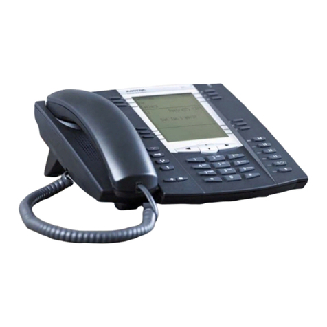
Avaya Compact DECT User manual

Compact DECT
Installation Manual
38DHB0002UKFH – Issue 5 (27t
h
October 2003)

Page 2 - Contents
Page 2 Compact DECT
Contents 38DHB0002UKFH – Issue 5 (27th October 2003)
Introduction.............................................3
General ............................................................ 3
Compact DECT in Detail.................................. 4
The Compact DECT System............................ 5
Compact DECT Base Station (CDBS) ............... 5
Repeater............................................................. 5
20DT Handset .................................................... 5
Single Chargers.................................................. 5
Site Surveys ............................................6
Introduction ...................................................... 6
Base Station Coverage: In Theory............................. 7
Base Station Coverage: In Practice ........................... 7
Using the Site Survey Kit ........................................ 8
The Survey Base Station.................................... 8
Subscribing to the Survey Base Station ............. 9
Performing the Survey...................................... 10
Preparing for Installation.............................11
Unpacking ......................................................... 11
Tools Required ................................................... 11
Additional Parts Required...................................... 11
PBX Restrictions................................................. 12
Environmental requirements .................................. 12
Power Supply Requirements.................................. 12
Cabling & Trunking Requirements ........................... 12
EMC Requirements ............................................. 12
Base Station Installation .............................13
Mounting the Base Station..................................... 13
Power Fail Circuits............................................ 14
Registering Handsets........................................... 15
Subscribing Handsets .......................................... 16
Auto Subscribing Handsets.................................... 17
Removing a Subscription ...................................... 17
Subscribing GAP Compatible DECT Handsets........... 18
System Testing & Handover .................................. 18
Repeater Installation...................................19
Introduction........................................................ 19
Locating Repeater Base Stations ............................ 20
Installing a Repeater ............................................ 20
Mounting the Repeater(s)................................. 20
Attaching an Directional Aerial ......................... 21
The Repeater Setup Program ................................ 21
Installing the Repeater Setup Program ............ 21
Connecting a Repeater for Programming ........ 21
Configuring a Repeater .................................... 22
Using Windows CCFP Administration........... 23
The CCFP Administration Program ......................... 23
Programming Connection .................................23
Installing CCFP Admin ......................................... 23
Starting CCFP Admin - Direct Connection................. 24
Changing the Communications Configuration ............ 24
Starting CCFP Admin - Modem Connection............... 25
MSF Status ....................................................... 26
Status Message.................................................. 26
Uploading Flash Software ..................................... 26
Saving and Loading Files...................................... 27
Printing the Setting .............................................. 27
Exiting CCFP Administration.................................. 27
CCFP Options Menus ................................. 28
Introduction ....................................................... 28
Preferences ....................................................... 28
Advanced Options.............................................28
PC/CCFP Version. ............................................29
Diagnostics........................................................29
Debug .............................................................. 30
INDeX Integration ................................. 31
Overview........................................................ 31
Mobile Twin Numbers .................................... 31
DECT Integration ........................................... 32
IP Office Integration ............................. 33
DECT Integration ................................................ 33
Installation Overview.........................................34
DECT Configuration Software ................................ 35
DECT Software Installation...............................35
IP Office Licences .............................................35
IP Office User Configuration .............................35
DECT Handset as a Slave of a Desktop Phone36
Call Waiting Indication ......................................38
Voicemail Pick-up .............................................39
System Diagnostics and Testing.................. 40
Base Stations Signal Checks ................................. 40
Handset Software Version..................................... 40
Battery Condition ................................................ 40
MSF Messages .......................................... 41
Overview........................................................... 41
Composing Messages.......................................... 42
Sending Messages.............................................. 42
Message Groups ................................................ 43
Compact DECT Cables ............................... 44
Compact DECT Base Station to PC Programming Cable44
Compact DECT Base Station to Modem Programming
Cable ............................................................... 44
Index........................................................ 45
Contents
Introduction - Page 3
Compact DECT - Installation Manual Page 3
38DHB0002UKFH – Issue 5 (27th October 2003) General
Introduction
General
This manual covers the installation, maintenance and programming of an
Compact DECT system. It is intended for use by installers and maintainers
who have successfully completed an appropriate Compact DECT training
course.
The Compact DECT is a cordless telephone system designed to work with
most PABX switch systems. It provides the PABX with integrated support for
cordless handsets.
Communications Platform
Up to eight analogue extension ports
Compact DECT
Base Station Compact DECT
Repeater(s)
Max of six
Plug top
PSU
PC Cable
(not supplied)
Twisted Pair Cable
(not supplied)
Up to 8 Handsets
With max. of 6
Simultaneous calls
Plug orientation
Viewed from bottom
RJ11 RJ45
A
ccess fo
r
Power PC twisted pair cable
a b a b a b a b a b a b a b a b
V24 (INDeX) Cable
LAN (IP Office) Cable
(not supplied)
Required for DECT
Integration
A Compact DECT Base Station (CDBS) can support up to six simultaneous
calls and up to eight 20DT handsets. Each handset requires a dedicated two-
wire link between the CDBS and the Coms. Platform.
Compact DECT conforms to the DECT Generic Access Profile (GAP)
requirements. This allows other GAP handsets to be used on the system. It
also allows the Compact DECT handsets to be used on other GAP
compatible DECT systems.
Approvals:
–Electric: TBR 6 (DECT RF).
–Access Profile: TBR22 (GAP) Layer 1.
–EMC: ETS 300 329 (CE Labelling).

Page 4 - Introduction
Page 4 Compact DECT - Installation Manual
Compact DECT in Detail 38DHB0002UKFH – Issue 5 (27th October 2003)
Compact DECT in Detail
The Compact DECT (Digital Enhanced Cordless Telecommunications*) uses
cellular radio methods to handle multiple handsets on the same system at the
same time. It is designed for high density local area usage.
The Compact DECT system uses the frequency band of 1.88 to 1.9GHz. It
employs FDMA (Frequency Division Multiple Access) to divide each band
into ten separate carrier frequencies. TDMA (Time Division Multiple Access )
further sub-divides each carrier frequency into 24 time slots. 12 slots are
used for send and 12 for receive, i.e. two slots are required per conversation
on the carrier frequency, this is called TDD (Time Division Duplex).
The above method gives 120 call channels available to a DECT system (10 x
24 channels, 2 channels per call).
During a conversation, a handset continuously compares the speech quality
obtained in its time slot to that in the same time slot on another carrier
frequency. If the current signal falls below acceptable limits and the other
band is better, the handset will change over to that band.
The Compact DECT systems use DCS/DCA (Dynamic Channel
Selection/Allocation) to resolve availability of channels between handsets
and base stations. These processes allow a high density of handsets (on the
same or different DECT systems) to operate in the same area (provided
sufficient base station channels are available).
Speech within DECT is digitised using ADPCM (Adaptive Differential Pulse
Code Modulation). Traditional PCM digitises speech by sampling at time
intervals and assigning a value to the amplitude at each time interval. This
sequence of amplitude values is then sent as a digital signal. In ADPCM
information is only sent when their is a difference in amplitude. This requires
more processing electronics but allows lower signal rates to be used for the
same speech quality.
*Originally DECT stood for "Digital European Cordless Telephony" but this
was changed as use of the standard spread beyond the European market.

Introduction - Page 5
Compact DECT - Installation Manual Page 5
38DHB0002UKFH – Issue 5 (27th October 2003) The Compact DECT System
The Compact DECT System
This sections gives a brief overview of the elements within the Compact
DECT system.
Compact DECT Base Station (CDBS)
A CDBS unit supports up to six simultaneous handset calls. Using standard
telephony cable (not supplied) a CDBS can be placed up to 1Km from the
Communications Platform. The CDBS is designed for wall mounting and is
supplied with a plug top PSU fitted with 2 mtrs of cable.
– Size: 165mm wide x 165 high x 50mm deep.
– Power: Power from a 230V, 50Hz plug top PSU, (9VDC, 0.6A).
Repeater
A Repeater works in conjunction with a CDBS to extend that CDBS's area of
coverage. Two versions are available; a standard repeater and one that can
have an optional directional aerial fitted to increase the distance from the
associated CDBS (up to 1km line of sight).
Each Repeater is programmed to associate with a particular CDBS using a
Repeater Setup program. The Repeater can handle up to two simultaneous
calls. These calls are 'borrowed' from the CDBS. Hence, each call routed via
the Repeater reduces the number of calls that the CDBS can handle.
The Repeater does not need any wiring connection to the CDBS. The
Repeater is designed for wall mounting and is supplied with a plug top PSU
fitted with 2 mtrs of cable.
Size: 100mm wide x 100 high x 40mm deep (inc. wall mounting bracket).
Power: Power from a 230V, 50Hz plug top PSU, (9VDC, 300mA).
20DT Handset
Each handset is supplied with a battery.
– Weight: 121g ±10g (including battery).
– Size: 143mm x 48mm x 26mm.
– Power: Fully charged battery; 10 hours speech, 90 hours standby.
Full battery recharge, 3.5 hours in handset charging slot.
Note: A label, located beneath the battery pack, provides both the handset
registration number and the software level (at time of manufacture).
Alternatively, on latter models, you do not have to remove the back
cover. Simply key *999*84* and press 9. Handsets are supplied with
the battery disconnected. Ensure that the battery is connected before
use.
Single Chargers
The single chargers are designed as a free-standing desk units.
The single chargers are supplied with a mains power supply unit appropriate
to the ordering country.

Page 6 - Site Surveys
Page 6 Compact DECT - Installation Manual
Introduction 38DHB0002UKFH – Issue 5 (27th October 2003)
Site Surveys
Introduction
A site survey is performed using a separately supplied Site Survey Kit.
A site survey is the most crucial part of any Compact DECT installation.
It is the stage at which future success or failure of the installation will
probably occur.
Most issues of customer satisfaction will stem from the site survey and the
resultant positioning of the base station and the Repeater(s) (see page 20).
From the customer's point of view, two keys factors must be assessed:
– The area of coverage required:
– The number of simultaneous users within different areas:
A CDBS can support 6 simultaneous calls. Where Repeaters are used,
they support two simultaneous calls, but these are 'borrowed' from the
CDBS. Hence, each call routed via Repeaters reduces the number of calls
that the CDBS can handle.
During the site survey, you will be attempting to determine three factors to
achieve the customers requirements:
– The best positioning of the CDBS
– The number of Repeaters required.
– The best positioning of the repeaters.
To fulfill this you need to obtain the following details:
– Building Measurements:
Accurate building plans are an essential aid to both the site survey and
also for later fault analysis.
– Signal Strength: (RSSI - Radio Signal Strength Indication)
From potential base station positions, what is the range of the base station
signal at sufficient signal strength for reliable operation.
– Speech Quality: (Q52)
Interference, weak signals and reflected signals lead to errors in the digital
signal that cannot be corrected. From potential base station position, what
is the range before the bit error rate becomes unacceptable.

Site Surveys - Page 7
Compact DECT - Installation Manual Page 7
38DHB0002UKFH – Issue 5 (27th October 2003) Base Station Coverage: In Theory
Base Station Coverage: In Theory
Given ideal open field conditions, the range between a handset and base
station can be up to 600 metres. Within a building, with signal strength being
absorbed and reflected signals giving increased error rates, the effective
range (R) is more realistically between 50 metres and 150 metres.
A single base station's area of coverage is ΠxR2.
Base Station
R
Be aware that the following is assumed:
– The building structure is even and so the CDBS has the same range in
all directions.
– That a CDBS does not only operate in 2-dimensions. In reality the signal
forms a sphere rather than a circle.
Base Station Coverage: In Practice
In practice, no rules can be given for base station coverage. Coverage is
affected by too many factors that are unique to each site. We can only guide
you as to those things that are likely to affect base station coverage.
Obvious causes of signals problems:
Metal surfaces.
Concrete thickness greater than one metre.
Beware of:
Windows with reflective film or specialised glass: (e.g. Pilkington 'K')
These produce increased signal reflection and reduced signal pass-
through.
Wire Meshes and Grills with apertures of less than 4cm:
These block signals as effectively as continuous metal sheet.
Fire Doors:
These block the signals. In multi-occupancy building such as hotels the
high number of fire-doors may be a problem.
Stair Wells:
In modern office buildings, stair wells frequently combine concrete building
supports, fire doors and the intervening floor material, making them a
special problem.
Screened Rooms:
Typically found in offices involved with TV, video and radio production, but
also possible in computer centers.
Opportunities to be aware of:
In multi-storey buildings, if the building construction allows, a base station on
one floor can also serve the floor above or below.

Page 8 - Site Surveys
Page 8 Compact DECT - Installation Manual
Using the Site Survey Kit 38DHB0002UKFH – Issue 5 (27th October 2003)
Using the Site Survey Kit
Guidance on where to start the survey and order in which to do a survey is
difficult, each case is unique and much relies on experience. Ensure that
conditions are as near to normal as possible, i.e. if possible do the survey on
a normal working day when the building is in use. Check which areas you
can enter and when.
The Survey Base Station
The Survey Base Station is a DECT Base Station is able to transmit without
requiring connection to a Coms. Platform. It is supplied with a suitable mains
power supply unit. As well as providing an RSSI/Q52 signal it can accept
audio input via a 3.5mm audio-jack input for a manual audio quality check.
Power Supply Input:
9VDC 150mA.
Subscribe
Button
Audio Input
– Power Socket:
The Survey Base Station is supplied with a suitable power supply
terminated with an RJ11 connector. The connector uses Pin 6 (-ve) and
Pin 5 (+ve) to provide a 9V dc, 150mA supply.
– Audio In Socket:
Standard 3.5 mono jack socket input.
– Subscribe Button:
If pressed and held for 3 seconds, puts the Survey Base Station in
subscribe mode for the following minute. The base stations system ID is
printed on its back. Its account number is 1234 (on older versions this may
be 12345678).
Site surveys may also be carried out using an Compact DECT Base Station.
In which case an extension cable should be used to provide a movable
power source. The survey process is the same except handset subscription
(see Subscribing Handsets on page 16).

Site Surveys - Page 9
Compact DECT - Installation Manual Page 9
38DHB0002UKFH – Issue 5 (27th October 2003) Using the Site Survey Kit
Subscribing to the Survey Base Station
Up to eight handsets can be subscribed to the Survey Base Station. All these
handsets can display the RSSI signal quality simultaneously but only one can
receive the audio input at any time. Normally only one handset is subscribed
to the Survey Base Station.
1. Connect the Survey Base Station to it's power supply and switch on.
2. Turn the handset on. Assign it a number between 1 and 8 by dialling
*99972*xwhere xis the number between 1 and 8 (each handset must
have a discrete number). Then press 9.
3. Press MENU and the >key until LOGIN appears and then press 9.
SELECT LOGIN appears. Before subscribing to system, you are
recommended to remove all other subscriptions (steps 4-6).
4. Press >until SUBSCRIPTION REMOVE appears and then press 9.
5. Enter the password (default 0000) and press 9to display
SUBSCRIPTION REMOVE? Press 9to display any previously entered
System ID (appears below SYSTEM X, where X = 1 to 4). Press 9to
remove.
6. You are returned to SUBSCRIPTION CREATE. Press >until
SUBSCRIPTION REMOVE appears. Repeat from step 4 for all
previously entered System IDs.
7. When completed, press MENU twice and then press >until LOGIN
appears. Press 9to display SELECT LOGIN and press 9again to
display SYSTEM X, where X = 1 to 4). Use >to select required system
number and press 9.
8. Press >to display SUBSCRIPTION CREATE and the press 9to begin
subscription. The handset is searches for a system to which it can
subscribe. Press and hold the subscribe button on the Survey Base
Station for 3 seconds. The Survey Base Station will then stay in
subscribe mode for one minute.
9. Use the <and >buttons to display the ID numbers of available DECT
systems found by the handset. Look for the ID number of the Survey
Base Station (printed on the back of the Survey Base Station) and then
press 9.
10. Use the <and >to select which system number you want the Survey
Base Station assigned to and then, at the AC: prompt, enter 1234 (or on
older systems 12345678) and press 9.
11. SUBSCRIPTION WAIT appears. When successfully subscribed, the
handset bleeps. Should SUBSCRIPTION FAILED appear, repeat from
step 8.

Page 10 - Site Surveys
Page 10 Compact DECT - Installation Manual
Using the Site Survey Kit 38DHB0002UKFH – Issue 5 (27th October 2003)
Performing the Survey
Position the Survey Base Station in the potential position for a base station
installation. Connect the power supply. If possible, also connect an audio
source via either the telephone line or audio jack sockets.
1. With a subscribed handset on-hook, dial *99981* and press ENTER.
2. The handset display shows the signal quality.
RPN: 01 <Base station number.
Q52: 52 <Speech quality.
RSSI: 64 <Signal strength.
3. Take the handset off-hook as this will ensure more realistic figures.
– If you have connected an audio source you will hear it whilst off-hook.
Use this facility to check the audio quality (only one handset can be
off-hook and receive the audio source at any time).
4. Check the boundaries of the Survey Base Stations coverage where Q52
is greater than 52 and RSSI is greater than 64. Mark this area on the
building plans for all areas that the CDBS might have to serve.
5. Where Repeaters are to be used, repeat the above process (see page 19
for CDBS/Repeater overlap).
6. To return the handset to normal operation, press and hold <until you
hear a short bleep.

Preparing for Installation - Page 11
Compact DECT - Installation Manual Page 11
38DHB0002UKFH – Issue 5 (27th October 2003) Unpacking
Preparing for Installation
Unpacking
1. Do not start unpacking until the equipment is at the site of installation.
2. Before unpacking check for any signs of damage that has occurred
during transit. If any damage exists bring it to the attention of the
carrier.
3. Check all cartons against the packing slip. Report any errors or
omissions to the dealer who supplied the equipment.
4. Whilst unpacking the equipment, retain all the packaging material.
Fault returns are only accepted if repackaged in the original packaging.
5. Visually inspect each item and check that all the necessary
documentation and accessory items have been included. Report any
errors or omissions to the dealer who supplied the equipment.
6. Ensure you read and understand any documentation included with any
item.
Tools Required
General:
– 0.5mm flat blade screwdriver.
– No.1 Phillips Crosspoint.
– Cutter/knife for cable ties.
– Cable ties - 3mm x 50mm.
– Drill and masonry drill bits
– Tape measure (up to 500mm).
– Spirit level.
– Digital voltmeter (DVM).
Programming:
– Windows 3.x/95/2000 or NT PC with serial port supporting 19.2K baud
minimum.
Additional Parts Required
The following items are required in addition to those supplied by Avaya.
Compact DECT Base Station:
– Single-twisted pair cable (Type CW1308) from Coms. Platform/MDF to
CDBS.
– 1 x DCU Programming/Integration cable as required (see page 44)
Compact DECT Repeater:
– No additional parts are required.

Page 12 - Preparing for Installation
Page 12 Compact DECT - Installation Manual
PBX Restrictions 38DHB0002UKFH – Issue 5 (27th October 2003)
PBX Restrictions
– Collective Ringing Groups:
Including a large number of Compact DECT handsets in a collective
ringing group can cause unpredictable results.
– Power Fail Circuits:
Compact DECT DAB circuits are not approved for direct connection to
PSTN analogue trunks. This is not a problem when connected via a PBX
except if a PBX directly connects some analogue extensions to analogue
trunks during PBX power failures. See Power Fail Circuits on page 14.
Environmental requirements
The planned locations for all parts of the system must meet the following
requirements:
– Check that the area is a well ventilated area, having a temperature range
of 0°C to +40°C and a humidity range of 10% to 90% non-condensing.
– Check there are no flammable materials in the area.
– Check there is no possibility of flooding.
– Check that no other machinery or equipment needs to be moved first.
– Check that it is not an excessively dusty atmosphere.
– Check that the area is unlikely to suffer rapid changes in temperature and
humidity.
– Check for the proximity of strong magnetic fields, sources of radio
frequency and other electrical interference.
– Check there are no corrosive chemicals or gasses.
– Check there is no excessive vibration or potential of excessive vibration,
especially on the cabinet mounting surface.
Power Supply Requirements
Both the Compact DECT Base Station and Repeater(s) are designed to
operate from a standard 230V (±10%), 50Hz single-phase main supply. The
Base Station is rated at 5.4VA and each Repeater is rated at 2.7VA for power
consumption.
The use of a UPS to support the system during mains power failure is highly
recommended. This equipment also provides mains conditioning for the
system. Contact Avaya for details of preferred and tested suppliers and
models.
Cabling & Trunking Requirements
All cables and wires should be run through protective trunking or ducts
wherever possible.
Unless otherwise stated, all devices connect using standard telephone cable
(type CW1308). This can be single or multiple pair cable.
EMC Requirements
The Compact DECT system is EMC approved and carries CE mark approval.
For a particular installation to be EMC compliant, it must meet the following
requirements at all times:
– Only EMC approved equipment must be used.
– You must install all units with their covers in place.

Base Station Installation - Page 13
Compact DECT - Installation Manual Page 13
38DHB0002UKFH – Issue 5 (27th October 2003) Mounting the Base Station
Base Station Installation
Mounting the Base Station
The Compact DECT Base Station (CDBS) is supplied with a plug top PSU
fitted with 2mtrs of cable that terminates in a modular plug. Screws and
fixings, for wall mounting the CDBS, are also supplied. A CDBS can be
placed up to 1Km from the MDF.
Correct positioning of the Base Station is vital to the performance of
the whole system. Before installing the CDBS, ensure that you have
accurate plans for its location (see Site Surveys on page 6).
To mount the CDBS, perform the following:
1. Check the proposed position of the CDBS and ensure that:
– A mains power supply is within 2 metres.
– The distance between the Coms. Platform and the CDBS is within
1Km.
– There is a minimum of 200mm's clearance on all sides of the CDBS.
2. Turn the CDBS over onto it's back and remove the top cover by releasing
the four retaining tags clips (one in each corner).
Cable entry break
Wall mounting
securing screw holes
PCB securing screw hole
PCB retaining lugs ( 2 off) PSU and PC connectors entry points
Top cover securing clips holes (4 off)
Cable Clamp
Use over
appropriate
retaining pillars
3. Remove the PCB by removing the securing screw and sliding the PCB
up and out from the retaining lugs. Put the PCB in a secure place.
4. Use the CDBS base as a template to mark the required holes. Ensure
that the CDBS is level. Drill and insert the wall fixings for the No.6 round-
head screws for all three holes. Insert the top two screws only, leaving
the heads 5mm from the wall surface. Do not secure the CDBS to the
wall (using another No. 6 screw in the third hole) until all cabling has
been completed.
5. Break-out the appropriate cable entry point and run a sufficient length (to
reach retaining block with a minimum of 5cm spare) of twisted pair cable
into the CDBS base. Secure cable, using clear plastic cable clamp and
screws provided, to appropriate retaining pillars.
6. Mount the CDBS onto the screw heads, using the key-slots at the back of
the base station, and secure with a No. 6 screw in the third hole.

Page 14 - Base Station Installation
Page 14 Compact DECT - Installation Manual
Mounting the Base Station 38DHB0002UKFH – Issue 5 (27th October 2003)
7. Replace the PCB and secure with the securing screw.
8. Remove minimum of 5cm outer sheath from cable. Connect the twisted
pairs (see below) to the fast connector block as follows:
– Strip 5mm from the ends of the eight (max.) twisted pairs.
– Starting at channel 1, socket 'a'; push the 0.5mm screwdriver into
hole 1 to release the internal spring on the fast connector and
simultaneously insert the stripped end of the a-side of the first pair
into hole 3. Release the screwdriver and test connection by gently
tugging on wire.
– Repeat for with the b-side wire of the first pair; e.g. channel 1, socket
'b' using hole 3.
– Repeat for the next seven twisted pairs.
PCB securing screw
PSU and PC connector sockets
Fast retaining bloc
k
for twisted pairs
1 2 3 4 5 6 7 8
a b a b a b a b a b a b a b a b
Hol e 1
Hol e 2
Hol e 3
Bootstrap pins
Bootstrap shorting
strap in normal
positi on
Ring and trip channels
Not Use
d
9. Feed the surplus twisted pair cable back out of the CDBS housing.
10 Ensure that the bootstrap shorting strap is in the 'normal' position and clip
the front cover back on.
11. Connect the other ends of the twisted pair cables to the Coms. Platform
analogue ports.
12. Connect the CDBS to the PC, either directly or via a modem.
See page 44 for cable details.
13. Push the PSU modular plug into it's socket on the CDBS and connect the
plug top PSU to the mains power supply.
14. The lamp in centre of the front of the CDBS will light green.
Other lamp statuses are:
- Red followed by green = flash programming mode or fault
- Fast blinking red = empty system with master handset subscription not
allowed
- Fast blinking green = empty system with master handset subscription
allowed
- Slow blinking red = in operation with maximum active connections
(busy)
- Slow blinking green = in operation with active connections (busy).
Power Fail Circuits
Compact DECT DAB channels are not approved for direct connection to the
PSTN (this is not due to any technical restrictions). As a result, DAB
channels must not be connected to analogue PBX extensions which connect
directly to analogue trunks during PBX power failures.

Base Station Installation - Page 15
Compact DECT - Installation Manual Page 15
38DHB0002UKFH – Issue 5 (27th October 2003) Registering Handsets
Registering Handsets
The Registration page of CCFP Administration displays all the settings for
handsets (see The CCFP Administration Program on page 23). The top section of
the screen shows all the available channels and the handset settings. The
lower part of the screen shows the settings for an individual channel. This
menu also provides options to Delete or Move users.
Editing User Settings:
1. In the Choose User (At Location) section select the IWU and Channel.
2. In the Current User Data section select:
– Serial No.:
The handset serial number.
– This is found on a label covered by the handset battery. It consists
of a 5 digit handset type and then a 7 digit handset number
separated by a space.
– For other GAP compatible DECT handsets it is possible to
discover the serial number (see page 18).
– AC No.:
An option account code of up to 7 digits. If set then the account code
is entered by the handset as part of the subscription process.
– User Name*:
Up to 10 characters. Shown on the DECT handset called by the user.
– Local No.:
The handsets extension number on the attached PBX (must be the
same number as the 2-wire/SLT user's number).
– Standby Text*:
Up to 10 characters. Shown when idle but in range of a base station.
– Presentation Text*:
Up to 10 characters. Shown on the DECT handset calling the user.
A B
'A' calls 'B'
'A' ll 'B'
B's Presentation Tex
t
A's User Name
*Though overridden by Compact DECT Integration, it is still sensible to set
these options.

Page 16 - Base Station Installation
Page 16 Compact DECT - Installation Manual
Subscribing Handsets 38DHB0002UKFH – Issue 5 (27th October 2003)
Subscribing Handsets
Once a handsets details have been entered into the Registration screen of
CCFP Administration, the handset can be subscribed to the system.
Enabling Subscription
1. Run CCFP Administration (see page 23).
2. Check that the handset details have been correctly entered on the CCFP
Registration screen (see page 15).
3. Select Options and then Preferences. Click on the Advanced Options
tab. Click on Allow Subscription (a tick mark appears when allowed).
4. Use the appropriate process below to subscribe the handset.
5. After subscribing the handset(s), switch Allow Subscription off (no tick
mark).
To subscribe a 20DT Handset
It is recommended to only subscribe one handset at a time and that all
previously subscribed System IDs are removed prior to subscribing for the
first time (see page 17).
1. Press MENU and then >until LOGIN appears, then press 9. SELECT
LOGIN appears
2. Press >until SUBSCRIPTION CREATE appears, then press 9.
3. SEARCH ID appears. Press >until required system ID number appears.
(The system ID is printed on the back of the Compact DECT Base
Station).
The handset displays the ID's of any systems in range. If there are
several systems locally, use <and >to display the different ID numbers
found.
4 When the required system ID is displayed, press 9
5. Press >until CREATE SYSTEM 1 appears, press >until required
SYSTEM number appears.
6. When the required SYSTEM number appears.
7. AC: _ _ _ _ _ _ also appears.
If required enter an Account Code and/or press 9.
8. SUBSCRIPTION WAIT appears. If for some reason your handset cannot
subscribe it displays FAILED. Press to try again from step 2 above or
press MENU to stop.
9. When successfully subscribed, your handset bleeps and your extension
number is displayed.

Base Station Installation - Page 17
Compact DECT - Installation Manual Page 17
38DHB0002UKFH – Issue 5 (27th October 2003) Auto Subscribing Handsets
Auto Subscribing Handsets
When moving between two locations, both equipped with IP Office and
Compact DECT systems, you can set a handset to automatically subscribe to
the other DECT system provided that the handset at been registered on both
systems (see page 15).
To set auto subscription on a 20DT Handset
1. Press MENU and then >until LOGIN appears, then press 9. SELECT
LOGIN appears
2. Press 9CURRENT SYSTEM and the ID of that system appears.
3. Press >to select AUTO LOGIN and then press 9to finish.
Removing a Subscription
If necessary, you can remove a subscription from the handset. Do not do
this lightly as you may not be able to re-subscribe without assistance from
your System Maintainer.
1. Press MENU and then >until LOGIN appears, then press 9.
2. SELECT LOGIN appears.
3. Press >until required SUBSCRIPTION REMOVE appears, then press 9.
4. Enter your password and press 9.
5. SUBSCRIPTION REMOVE appears, press 9and then press >until the
system you wish to remove appears
6. Press 9again to remove the system.
– If the system removed was the one currently in use, you need to
LOGIN again (see page 16).
7. Press MENU to finish.

Page 18 - Base Station Installation
Page 18 Compact DECT - Installation Manual
Subscribing GAP Compatible DECT Handsets 38DHB0002UKFH – Issue 5 (27th October 2003)
Subscribing GAP Compatible DECT Handsets
GAP compatible DECT handsets can be subscribed to the Compact DECT
system. To do this you will require the original handset manufacturers
instructions for subscribing that handset.
A difficulty may arise in determining the serial number of the handset so that
it can registered on the Compact DECT systems prior to subscription.
To determine a handsets serial number
1. Set the Compact DECT system to allow subscription (see Subscribing
Handsets on page 16).
2. Go to the CCFP programs Status page and set the Status Level to
Level 2 (see MSF Status on page 26).
3. From the non-Compact DECT handset attempt to subscribe to the
Compact DECT system using the handset manufacturer's instructions.
The subscription will fail as the handset is not registered in the Compact
DECT database but during the attempt its serial number will be displayed
in the Receive Status display.
4. Note the serial number and add the handset to the registered handsets
(see Registering Handsets on page 15). You should now be able to
subscribe the handset.
System Testing & Handover
After completing installation, including any Repeaters (see page 19) and
handset subscription, perform the following checks:
– Make test calls from all handsets.
– With a call connected, move through the areas that should be covered by
the Base Station. Check that no unexpected 'black spots' exist.
– With a call connected, move through the areas that should be covered by
the Repeaters. Check that no unexpected 'black spots' exist.
Ensure that the customer is satisfied with the installation. Make sure they are
aware of the following:
– Reporting Faults:
Make the customer aware of the details required when reporting any
faults. Since this a cordless system, details of the handset user's location
at the time of a fault is crucial. Maintaining a record of the location of
faults may reveal black spots or high usage areas.
– Hearing Aids:
Make the customer aware that all cordless and mobile telephone
systems can cause background noise on some hearing aids.
– Safety Areas:
Make sure the customer is aware of their responsibility to indicate to
handset users any areas where handsets should not be used and should
be switched off for reasons of safety. The 20DT handsets are not
classified as 'intrinsically safe electrical equipment' (a special
classification for electrical equipment for use in hazardous areas).

Repeater Installation - Page 19
Compact DECT - Installation Manual Page 19
38DHB0002UKFH – Issue 5 (27th October 2003) Introduction
Repeater Installation
Introduction
The Compact DECT Repeater allows you to extend the range of coverage of
a Compact DECT Base Station (CDBS) without requiring more wiring to the
system. The only physical connection required for each Repeater is a mains
supply. Two versions of the Repeater are available; a standard Repeater and
a Repeater that can have an optional directional aerial fitted (see below).
Up to six Repeaters can be added to an existing CDBS as shown below.
Repeater jump
Repeater 3
Repeater 1
Repeater 2 Repeater 4 Repeater 5 Repeater 6
Note: When programming for Repeater Jumps, you must start with
Repeater 4 to CDBS, followed by Repeater 5 to 4 and finally
Repeater 6 to 5.
E.g. Repeater 4 acts as a base station for Repeater 5, which in
turn acts as a base station to Repeater 6.
The range at which a Repeater can work will typically be between 50 and
150m within a building. Each Repeater works in conjunction with an existing
parent DECT Base Station. These calls are 'borrowed' from the CDBS.
Hence, each call using a Repeater reduces by one the capacity of its parent
CDBS (capacity of 6 calls). A Repeater jump link can only handle two
simultaneous call at any one time.
The use of a directional aerial allows the Repeater to be placed up to 1000m
from its parent base station (subject to intervening structures) as follows.
Base Station
Repeater
Repeater
Repeater
Repeater
External
Antenna
Up to 1Km line of sight

Page 20 - Repeater Installation
Page 20 Compact DECT - Installation Manual
Locating Repeater Base Stations 38DHB0002UKFH – Issue 5 (27th October 2003)
Locating Repeater Base Stations
Repeater base stations are subject to the same positioning requirements as
a CDBS (see Site Surveys on page 6). Currently the only method for doing a
site survey for a Repeater is in conjunction with an installed CDBS.
As for a CDBS, the correct performance and functioning of a Repeater
requires an accurate site survey. Make sure you include sufficient
overlap between CDBS and Repeater(s).
Installing a Repeater
To install a Repeater, it must be wall mounted and configured. Use the
procedures below to mount and configure a Repeater.
Mounting the Repeater(s)
Each Repeater is supplied with a plug top PSU fitted with 2mtrs of cable that
terminates in a modular plug. Screws and wall plugs for mounting the CDBS
are also supplied.
To mount a Repeater, perform the following:
1. Check the proposed position of the Repeater and ensure that:
– A mains power supply is within 2 metres.
– There is a minimum of 200mm clearance on all sides of the
Repeater.
2. Use the Repeater Wall Mounting Bracket (see figure below) as a
template to mark the required holes. Ensure that the Repeater is level.
Drill and insert the wall fixings for the No.6 round-head screws.
3. Run the PSU modular plug through the access hole before fixing the
bracket to the wall with the two No. 6 round head screws.
4. Push the PSU modular plug in to it's socket on the Repeater.
5. Slide the Repeater onto the mounting bracket (a firm push is required to
slide the Repeater lugs over the pins on the wall mounting bracket).
6. Connect the plug top PSU to the mains power supply.
7. The lamp in centre of the front of the Repeater will light as follows:
- a steady red when in idle state
- will flash red when Repeater is not synchronized with CDBS
- two short flashes whenever a connection is made via Repeater.
Wall mountin
g
securing screw slot
s
PSU plug entry point
Top
–
viewed from front
Table of contents
Other Avaya VoIP manuals

Avaya
Avaya Tandberg 150 MXP User manual

Avaya
Avaya Aura Communication Manager Technical manual

Avaya
Avaya Compact Business Center User manual

Avaya
Avaya PARTNER Phone User manual

Avaya
Avaya Communication Manager Service manual

Avaya
Avaya IP Office Phone Manager User manual

Avaya
Avaya EC500 User manual

Avaya
Avaya Communication Manager Service manual

Avaya
Avaya Power Over Ethernet Instruction Manual