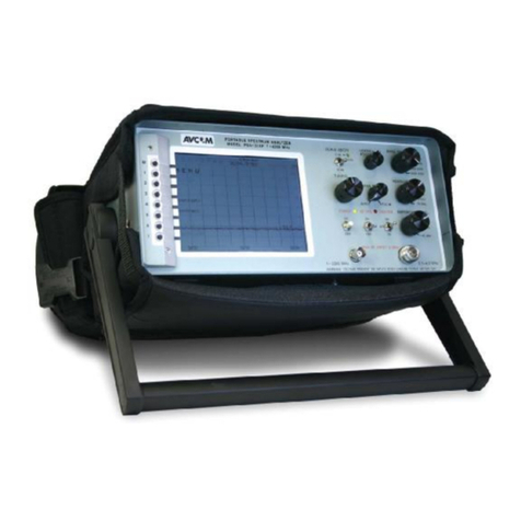
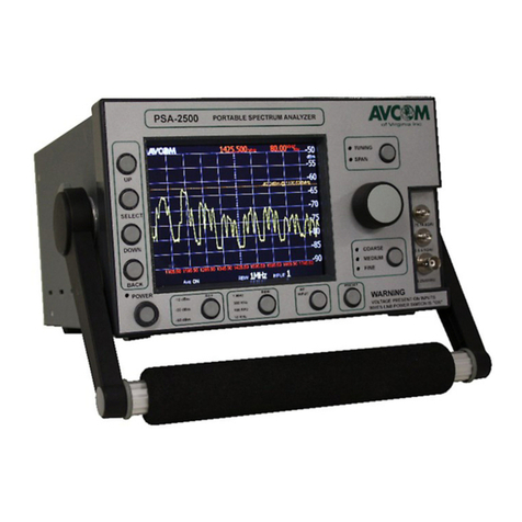
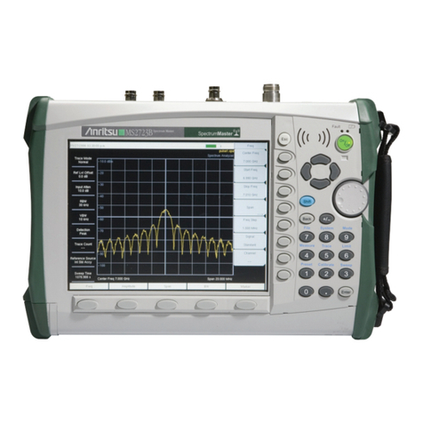
AVCOM SNG-2500C User manual

SNG-2500C User’s Guide
Avcom of Virginia SNG-2500C User’s Guide
7730 Whitepine Road Revision 001
Richmond, VA 23237
USA

. . . . .
Revision 001 SNG-2500C User’s Guide ii
. . . . . . . . . . . . . . . . . . . . . . . . . . . . . . . . . . . . . . . . . . . . . . . . . . . .
GENERAL SAFETY
If one or more components of your earth station are connected to 120 volt AC line current, it
is important that you ground all components of your system, particularly the antenna, to
reduce the possibility of dangerous electrical shock. When using instruments such as the
SNG-2500C, power hand tools, and any other appliance connected to an electrical outlet,
exercise great care to ensure that the device is grounded effectively to avoid electrical
shock. Do not use while standing in water, on damp earth, or while in personal contact with
a conducting surface such as a metal ladder or chair.
Also:
• Use a properly grounded electrical outlet or extension cord.
• Do not cut the grounding pin from the line cord plug.
• Ensure the antenna and other components of your earth station are properly grounded.
• Do not open the case - the warranty will be voided by doing so. No user-servicable parts
are inside.
. . . . . . . . . . . . . . . . . . . . . . . . . . . . . . . . . . . . . . . . . . . . . . . . . . . .
IMPORTANT CAUTIONS
• Do not couple the input of the SNG-2500C to high power RF sources such as walkie
talkies, CB radios, transmitters, etc. Signal levels in excess of +15 dBm can damage the
sensitive mixers in the instrument resulting in otherwise unnecessary expense and
repairs. Use only the external DC power supply included with the unit.
• Handle with care. The SNG-2500C Spectrum Analyzer is a precision instrument
designed for normal operating and handling conditions. It should be protected from
abuse such as dropping, throwing, and other rough handling. When being transported in
a vehicle, or shipped, the SNG-2500C must be cushioned and protected against shock
and vibration.

. . . . .
Revision 001 SNG-2500C User’s Guide 1
general safety .............................................................................................................. 1-ii
important cautions ....................................................................................................... 1-ii
1 Overview .......................................................................................................1-1
Improved Performance & Specifications .................................................................... 1-2
Versatile Graphical User Interface .............................................................................. 1-2
Features ....................................................................................................................... 1-2
2 Hardware .......................................................................................................2-1
The Front Panel ........................................................................................................... 2-1
The Back Panel ........................................................................................................... 2-3
3 Using the SNG-2500C ..................................................................................3-1
The Display Screen ..................................................................................................... 3-1
The Tools Menu .......................................................................................................... 3-2
Persistence .................................................................................................................................... 3-3
Waterfall ....................................................................................................................................... 3-5
The LO Offsets Menu ................................................................................................. 3-6
The LNB Power Menu (Optional) .............................................................................. 3-6
The Presets Menu ........................................................................................................ 3-7
The Saved Waveforms Menu ...................................................................................... 3-8
The Display Settings Menu ......................................................................................... 3-9
Video Flip ..................................................................................................................................... 3-9
Ride Peak Line ............................................................................................................................ 3-10
The System Settings Menu ....................................................................................... 3-10
4 Specifications ...............................................................................................4-1
Technical Specifications ............................................................................................. 4-1

Revision 001 SNG-2500C User’s Guide 1-1
. . . . .
. . . . . . . . . . . . . . . . . . . . . . . . . . . . . . . . . . .
O
VERVIEW
1
he SNG-2500C is Avcom’s answer to the discontinued
Tektronix 1705A with a feature set that gives the Satellite
Technician a very useful tool for finding and peaking on
satellites. The SNG-2500C is not only a spectrum analyzer, but also
a carrier monitor (that can simultaneously monitor up to six RF
inputs), with features such as carrier masking and screen shot capture
and recording. When used with the Avcom Graphical User Interface
(GUI), the SNG-2500C also offers Satellite ID and Automated Data
Acquisition (DAQ) with tolerance comparison and integrated e-mail
alerts. The SNG-2500C also offers L.O. Frequency Offset which
enables you to display the frequency in L-Band, C-Band, X-Band,
Ku-Band, or any custom band needed.
T

. . . . .
OVERVIEW
Improved Performance & Specifications
Revision 001 SNG-2500C User’s Guide 1-2
IMPROVED PERFORMANCE &
. . . . . . . . . . . . . . . . . . . . . . . . . . . . . . . . . . . . . . . . . . . . . . . . . . . .
SPECIFICATIONS
The new SNG-2500C was designed with excellent frequency and
amplitude accuracy as well as a wide variety of resolution bandwidth
selections ranging from 10kHz to 1MHz. These features enable you
to view and monitor small TT&C and data carriers found in many
satellite communications markets today. The front panel provides
independent control of Frequency & Span (with settings for Fine,
Medium and Coarse), enabling you to dial into the carrier and
control the display as needed.
. . . . . . . . . . . . . . . . . . . . . . . . . . . . . . . . . . . . . . . . . . . . . . . . . . . .
VERSATILE GRAPHICAL USER INTERFACE
The SNG-2500C can be monitored and controlled both locally from
the front panel with the color LCD or remotely using the Avcom
Graphical User Interface (GUI). Connecting via either the serial port
or Ethernet port, the remote GUI enables remote monitoring and
control from anywhere in the world via the Internet. If the SNG-
2500C is used in a SNG truck with a high speed cellular broadband
card, an inexperienced operator can get assistance (in the form of
remote monitoring and control) from anywhere in the world.
. . . . . . . . . . . . . . . . . . . . . . . . . . . . . . . . . . . . . . . . . . . . . . . . . . . .
FEATURES
• High Resolution Full VGA Color Display
• Fits into Tektronix 1700 Series Dual Mount tub designed for satellite news
gathering market
• Dual Wideband Switched Inputs; 4 and 6 inputs available
• DSP Technology enables refresh rates up to 13/sec
• Digital Tuning for Excellent Frequency Accuracy
• 4 Resolution Bandwidth Selections
• Ethernet & Serial Communications for Full Remote Control Capability
• User Friendly and Intuitive GUI

Revision 001 SNG-2500C User’s Guide 2-1
. . . . .
. . . . . . . . . . . . . . . . . . . . . . . . . . . . . . . . . . .
H
ARDWARE
2
his chapter explains how to use the controls on the front panel
and the connectors on the back panel.
. . . . . . . . . . . . . . . . . . . . . . . . . . . . . . . . . . . . . . . . . . . . . . . . . . . .
THE FRONT PANEL
Take a few moments to familiarize yourself with the front panel of
the SNG-2500C:
T
<TUNING/SPAN>
Button and Indicator
Lights
<ROTARY
ENCODER>
<SENSITIVITY>
Button and Indicator
Lights
<PRESET> Button
<POWER>
Button and
Indicator Light <REFERENCE
LEVEL> Button and
Indicator Lights
<RBW> Button and Indicator Lights
<RF INPUT>
Button and
Indicator Lights
Menu Buttons:
<UP> Button
<SELECT> Button
<DOWN> Button
<BACK> Button

. . . . .
HARDWARE
The Front Panel
Revision 001 SNG-2500C User’s Guide 2-2
The following table explains each of the front panel controls:
Control Description
. . . . . . . . . . . . . . . . . . . . . . . . . . . . . . . . . . . . . . . . . . . . . . . . . . . .
<UP> Button Scrolls the highlighting up through whatever menu is
currently displayed. If it is already at the top, the
highlighting wraps to the bottom of the menu. This button
is also used for toggling various menu options.
<SELECT> Button Selects the menu option that is currently highlighted. If no
menu is displayed, press the <SELECT> Button to display a
menu.
<DOWN> Button Scrolls the highlighting down through whatever menu is
currently displayed. If it is already at the bottom, the
highlighting wraps to the top of the menu. This button is
also used for toggling various menu options.
<BACK> Button Returns to the previously displayed menu. You can think
of the <BACK> Button as the opposite of the <SELECT>
Button.
<POWER> Button
and indicator
light
Press the <POWER> Button to apply power to the SNG-
2500C. Press it again to remove power. (If you can not
power the SNG-2500C down, hold the <POWER> button in
for 10 seconds and it will shut down.) The red indicator
light is lit whenever the SNG-2500C has power.
<REFERENCE
LEVEL> Button
and indicator
lights
Press the <REFERENCE LEVEL> Button to change the
reference level. The indicator lights show the new
reference level. If the reference level is too high, your
signal could be too strong to measure. If the reference level
is too low, your signal might not be visible at all.
<RBW>
(Resolution
Bandwidth)
Button and
indicator lights
Press the <RBW> Button to change the resolution
bandwidth. The indicator lights show the new RBW. Using
the proper resolution bandwidth makes it easier for you to
see smaller or larger signals.
<RF INPUT>
Button and
indicator lights
Press the <RF INPUT> Button to change to a different RF
input. The indicator lights show which RF input is being
monitored.
<PRESET> Button When you have discovered the best settings for a particular
signal, you can save those settings as a preset. By saving
the settings for each signal that you monitor, you can create
a library of presets. Press the <PRESET> button to cycle
through the presets.

. . . . .
HARDWARE
The Back Panel
Revision 001 SNG-2500C User’s Guide 2-3
. . . . . . . . . . . . . . . . . . . . . . . . . . . . . . . . . . . . . . . . . . . . . . . . . . . .
THE BACK PANEL
There are no controls on the back panel, but connections for power,
signal, and remote control are made here.
<SENSITIVITY>
Button
The <SENSITIVITY> Button controls the resolution of the
<ROTARY ENCODER>. A coarse resolution enables you to make
big changes quickly, while a finer resolution enables you to
make small adjustments precisely. The indicator lights
show which resolution is in effect.
<ROTAR Y ENCODER>Rotate the <ROTAR Y ENCODER>to change the frequency or the
span of frequencies being monitored. The function of the
<ROTARY ENCODER>is determined by the <RBW> Button and
the <TUNING/SPAN> Button.
<TUNING/SPAN>
Button
The <TUNING/SPAN> button determines whether the
<ROTARY ENCODER>changes the frequency or the span of
frequencies being monitored. The indicator lights show
which function is in effect.
Control Description
. . . . . . . . . . . . . . . . . . . . . . . . . . . . . . . . . . . . . . . . . . . . . . . . . . . .
Ethernet Port
RS-232 Port
(also known as a
Serial Port)
Power Input
RF Inputs

. . . . .
HARDWARE
The Back Panel
Revision 001 SNG-2500C User’s Guide 2-4
Connector Description
RF Input The signal to be monitored and/or analyzed comes in here.
Your system might have more than one RF Input. In that
case, you can switch between them from the front panel.
Ethernet Port Use this port to connect to the internet. A computer located
anywhere in the world can then use the Avcom Graphical
User Interface (GUI) to monitor and control the SNG-2500C.
You can also use this port to connect to a computer that is
physically close to you.
RS-232
(Serial) Port
Use this port to connect to a computer that is physically close
to you. The computer can then use the Avcom Graphical User
Interface (GUI) to monitor and control the SNG-2500C.
Power Input Connect the 15 volt DC, 3 amp capacity power supply
provided by Avcom to this port. The unit will not perform
correctly with a substitute.

Revision 001 SNG-2500C User’s Guide 3-1
. . . . .
. . . . . . . . . . . . . . . . . . . . . . . . . . . . . . . . . . .
U
SING
THE
SNG-2500C
3
o avoid the need for a large and complicated front panel, the
SNG-2500C uses a system of menus and sub-menus to
provide access to most of its features. You can navigate this
menu system by using the column of buttons above the <POWER>
button. Each of these buttons is described in detail in Chapter 1.
. . . . . . . . . . . . . . . . . . . . . . . . . . . . . . . . . . . . . . . . . . . . . . . . . . . .
THE DISPLAY SCREEN
Below is an example of what the screen might look like:
T
Frequency at
center of display
LO Offset feature
is on
Span, in MHz. This is the “scale”
of the Y axis.
Signal Strength (X axis)
Frequency (Y axis)
Persistence,
Waterfall, and
Averaging are
all on
LNB voltage is 13 volts,
and LNB 22KHz is off
(Your system may not
have this option.)
Current settings are stored in Preset 1
Signal is from RF Input 1
Resolution Bandwidth is 1MHz

. . . . .
USING THE SNG-2500C
The Tools Menu
Revision 001 SNG-2500C User’s Guide 3-2
Here is an example of what a menu looks like:
This chapter assumes that you know how to get into each menu and
make selections, and now you need to know what each menu option
does.
. . . . . . . . . . . . . . . . . . . . . . . . . . . . . . . . . . . . . . . . . . . . . . . . . . . .
THE TOOLS MENU
The Tools Menu contains tools that enable you to customize the
appearance of the waveform on the screen.
Tool Description
Average Averaging is a noise reduction feature that smooths out the
appearance of the waveform. Instead of displaying the exact
values of the signal strength, which are constantly changing,
it displays an average of the most recent values. You can
specify how many values are averaged. The higher you set
this parameter, the smoother the display will be.
Persistence Persistence is a feature that enables you to see where a
waveform has been in the recent past. For example, if a signal
drops sharply, you could see the drop for a period of time
after it has returned to normal. By changing the Mode, you
can customize this feature to show minimum levels,
maximum levels, or both. You can also specify the time
(measured in frames) the persistent waveform is displayed.
Main Menu (“Tools” is
selected)
Function of <SELECT>
button
Function of <UP> and
<DOWN> buttons

. . . . .
USING THE SNG-2500C
The Tools Menu
Revision 001 SNG-2500C User’s Guide 3-3
Persistence
The screen captures below illustrate the concept of persistence.
In the first example, the minimum level is being shown. The green
area below the waveform is the lowest level the waveform has
reached.
Waterfall Waterfall is another feature that enables you to see where a
waveform has been in the recent past. It does this by scrolling
the old waveforms up and to the right, creating a three-
dimensional view of how the waveform has changed over
time.
2dB / Div
Scale
This feature provides a close-up view of the waveform by
changing the scale shown on the right side of the display. In
2dB mode, each horizontal line on the display represents a
change of 2dB instead of the usual 5dB.
Tool Description

. . . . .
USING THE SNG-2500C
The Tools Menu
Revision 001 SNG-2500C User’s Guide 3-4
In the next example, the maximum level is being shown. The red area
above the waveform is the highest level the waveform has reached.
In the final example, both the minimum and maximum levels are
being shown. The green area below the waveform is the lowest level
the waveform has reached, and the red area above the waveform is
the highest level the waveform has reached.

. . . . .
USING THE SNG-2500C
The Tools Menu
Revision 001 SNG-2500C User’s Guide 3-5
Waterfall
Below is an example of the waterfall display:
The 2D waterfall option shows the waterfall display as it would
appear if you were looking down from above:

. . . . .
USING THE SNG-2500C
The LO Offsets Menu
Revision 001 SNG-2500C User’s Guide 3-6
. . . . . . . . . . . . . . . . . . . . . . . . . . . . . . . . . . . . . . . . . . . . . . . . . . . .
THE LO OFFSETS MENU
The LO Offsets Menu enables you to select several options for the
LO (Local Oscillator) offsets.
. . . . . . . . . . . . . . . . . . . . . . . . . . . . . . . . . . . . . . . . . . . . . . . . . . . .
THE LNB POWER MENU (OPTIONAL)
The LNB Power Menu enables you to configure the power settings
for the LNB inputs. (LNB may be on any input, if your system was
ordered that way.) The menu below is repeated for each LNB input
in your system.
Option Description
Turn on -5.150GHz
Turn off -5.150GHz
By pressing the <SELECT> button, you can toggle the
LO Offset on and off. The frequency shown on the
display changes accordingly.
Select Offset Selecting this option displays the Select Offset Menu.
The offset you select from this menu is toggled on and
off by the first menu option. For example, if you select
the offset “User1 LO=7.500GHz”, the first option in
the LO Offsets Menu will become “Turn on
7.500GHz”.
Change User1 LO
Change User2 LO
If none of the offsets listed in the Select Offset Menu
are suitable, you can define two custom offsets. Select
either “Change User1 LO” or “Change User2 LO”,
then use the <UP> and <DOWN> buttons to change the
offset frequency as needed.
Option Description
LNB Input 1
LNB Input 2
Press the <SELECT> button to switch the LNB input on or off.
LNB Voltage Press the <SELECT> button to toggle between 13 and 18 volts.
LNB 22KHz Press the <SELECT> button to toggle between on and off.

. . . . .
USING THE SNG-2500C
The Presets Menu
Revision 001 SNG-2500C User’s Guide 3-7
. . . . . . . . . . . . . . . . . . . . . . . . . . . . . . . . . . . . . . . . . . . . . . . . . . . .
THE PRESETS MENU
When you have the display looking the way you want it, you can
save the settings to a preset location in memory. If you need to
change the settings to monitor a different signal, you can change
them back by recalling the preset. The settings saved by this function
are:
• Center Frequency
• Span
•LOOffset
• LNB (if present)
• RF Input
•RBW
• Reference Level
Option Description
Save Preset Press the <SELECT> button to save the current settings as
Preset 1. If you do not want to erase the settings in Preset 1,
press the <UP> or <DOWN> buttons until you find a preset that
is acceptable.
Set Max
Presets
Use the <UP> and <DOWN> buttons to change the maximum
number of presets. If you set this parameter to match the
number of presets that you use, you never have to scroll past
any unused presets.
Delete Single Use this option to delete the settings stored in a preset
location.
Delete All Use this option to delete the settings stored in all preset
locations.

. . . . .
USING THE SNG-2500C
The Saved Waveforms Menu
Revision 001 SNG-2500C User’s Guide 3-8
. . . . . . . . . . . . . . . . . . . . . . . . . . . . . . . . . . . . . . . . . . . . . . . . . . . .
THE SAVED WAVEFORMS MENU
The options on the Saved Waveforms Menu enable you to freeze a
waveform on the screen and simultaneously save it to a memory
location for later display. There are fifty memory locations available
for this purpose.
Here is an example of a saved waveform. The blue line is the saved
waveform, and the black line is the waveform currently being
monitored.
Use this
option... To...
Save To freeze a waveform on the screen and simultaneously save it
to a memory location.
Load From recall a waveform from a memory location and display it.
Clear Screen clear a frozen waveform from the screen.
Delete Single delete a waveform from memory.
Delete All delete all waveforms from memory.

. . . . .
USING THE SNG-2500C
The Display Settings Menu
Revision 001 SNG-2500C User’s Guide 3-9
. . . . . . . . . . . . . . . . . . . . . . . . . . . . . . . . . . . . . . . . . . . . . . . . . . . .
THE DISPLAY SETTINGS MENU
The options on the Display Settings Menu enable you to adjust the
appearance of the display to your liking.
Video Flip
Below is an example of how the screen looks before and after the
Video Flip function.
Use this
option... To...
Brightness select one of five levels of screen brightness.
Video Flip invert the screen colors.
Ride Peak Line display a line showing the peak level (the strongest signal
currently visible). This line changes continuously as the
peak level changes. You can also show or hide the legend
for the peak line. The legend moves with the peak line and
shows the signal strength and frequency of the peak.
Disp Ref Level show or hide the signal strength numbers on the right side of
the display.
Display Graph show or hide the vertical and horizontal lines behind the
waveform.
Display
Date/Time
show or hide the date and time in the lower left corner of the
display.

. . . . .
USING THE SNG-2500C
The System Settings Menu
Revision 001 SNG-2500C User’s Guide 3-10
Ride Peak Line
Below is an example of the Ride Peak Line feature.
. . . . . . . . . . . . . . . . . . . . . . . . . . . . . . . . . . . . . . . . . . . . . . . . . . . .
THE SYSTEM SETTINGS MENU
The options on the System Settings Menu enable you to change the
system settings.
Option Description
Bit Resolution Bit Resolution toggles between 8-bit or 12-bit amplitude
resolution.
Unit dB / dBmV This option toggles between dBm and dBmV.
Set Date / Time Use this option to set the system date and time.
Rotary Encoder
Function
The Rotary Encoder Function determines what happens
when you press the <ROTAR Y ENCODER>. It is disabled by
default, but you can program it to duplicate the function of
the <TUNING/SPAN> Button or the <SENSITIVITY> Button.
Auto Hide Menu When this option is off, a menu displayed on the screen
remains on the screen until you exit from the menu system
by pressing the <BACK> button. When this option is on, the
menu disappears after a few seconds. To bring it back,
press any of the Menu Buttons.
System Info This option displays information about the system.

Revision 001 SNG-2500C User’s Guide 4-1
. . . . .
. . . . . . . . . . . . . . . . . . . . . . . . . . . . . . . . . . .
S
PECIFICATIONS
4
pecifications are based on Avcom control system and
graphical user interface and may vary depending on the
control system used. Please contact Avcom for specifications
based on the selected platform. Specifications are subject to change.
. . . . . . . . . . . . . . . . . . . . . . . . . . . . . . . . . . . . . . . . . . . . . . . . . . . .
TECHNICAL SPECIFICATIONS
Frequency Coverage: 5 - 2500 MHz
Span Width: 0 - 1300 MHz
Resolution Bandwidth: 10kHz, 100kHz, 300kHz, 1MHz
RF Sensitivity: Greater than - 85 dBm Typical
Reference Levels: Selectable - 10, -30 & - 50 dBm
Scale: 5 dB/Div & 2dB/Div
Dynamic Range: 40 dB on Application Window
Amplitude Accuracy: +/- 1 dB typical
Frequency Accuracy: +/- 1kHz typical
Input Connector: “BNC” Type (others available)
Size: Width, Height, Depth 8.0” X 4.75” X 16.5”
Weight: 5 Lbs.
Power Requirements: +15 Volts DC, 3 Amps
Display: Full VGA Color LCD
Input Option: 2 standard, 4 or 6 optional
Connector Option: BNC is standard; F, N, SMA, TNC are
optional
S
This manual suits for next models
1
Table of contents
Other AVCOM Measuring Instrument manuals
Popular Measuring Instrument manuals by other brands
Panasonic
Panasonic PV-V4524S Service manual

Sibelmed
Sibelmed DATOSPIR MICRO B Quick reference guide
Hioki
Hioki CM3286-01 quick start guide

Excelitas Technologies
Excelitas Technologies X-Cite XR2100 user guide
Farmcomp
Farmcomp wile 55 operating instructions
Hanna Instruments
Hanna Instruments HI 8734 instruction manual

PCB Piezotronics
PCB Piezotronics 357E92 Installation and operating manual

Fluke Calibration
Fluke Calibration 525B user manual

Wetekom
Wetekom SW-204BL instruction manual
Bartington
Bartington Mag-01 Operation manual

OWL
OWL OWLTrek WTO-M85 Operation guide

Apera Instruments
Apera Instruments WS100 instruction manual
