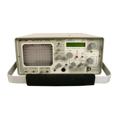
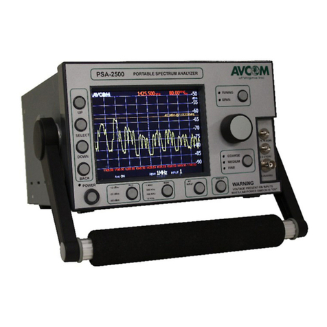
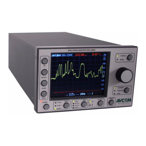
AVCOM PSA-37XP User manual

1
PSA-37XP
Portable SpectrumAnalyzerfor:
AVCOMof Virginia, Inc.
7730 WhitepineRoad
Richmond,VA 23237USA
804-794-2500
www.avcomofva.com
Owner’s Manual

2
AVCOM Publication No. PSA37XP
Revision 5
April2007
TABLE OF CONTENTS
Inputs, Outputs, andControls............................ 4
MenuQuick Reference ...................................... 8
Initial Menu .......................................................... 10
Start-UpMenu ..................................................... 11
OperationMenu................................................... 18
Preliminary Operation......................................... 24
BandAid Operation ............................................ 25
MFC Operation .................................................... 26
Specifications...................................................... 28
Battery Information............................................. 29
FrequencyAllocationCharts ............................. 31
FrequencyReference Definitions ...................... 32
Warranty .............................................................. 33
AVCOMof Virginia, Inc.
7730 Whitepine Road
Richmond, VA 23237
Phone (804) 794-2500
Fax(804) 794-8284
www.avcomofva.com.com
PSA-37XP(owners manual)

3
PLEASE READ CAREFULLY BEFORE USING THE PSA-37XP
GENERALSAFETY
IFONE OR MORE COMPONENTS OFYOUR EARTH STATION IS CONNECTED TO
120 VOLTAC LINE CURRENT. ITIS IMPORTANTTHATYOU GROUND ALL COMPONENTS
OFYOUR SYSTEM, PARTICULARLY THE ANTENNA, TO REDUCE THE POSSIBILITY
OFDANGEROUS ELECTRICAL SHOCK.
WHEN USING INSTRUMENTS SUCH AS THE PSA-37XP, POWER HAND TOOLS,
AND ANY OTHER APPLIANCE CONNECTED TO AN ELECTRICAL OUTLET, EXERCISE
GREATCARE TO ENSURE THATTHE DEVICE IS GROUNDED EFFECTIVELY TO
AVOID ELECTRICAL SHOCK. DO NOTUSE WHILE STANDING IN WATER, ON DAMP
EARTH, OR WHILE IN PERSONAL CONTACTWITH A CONDUCTING SURFACE SUCH
AS A METAL LADDER OR CHAIR.
ALSO:
♦ USE PROPERLY GROUNDED ELECTRICALOUTLETOR EXTENSION CORD
♦ DO NOTCUTGROUNDING PIN FROMLINECORD PLUG
♦ USE FUSES OFCORRECTAMPERAGE
♦ DISCONNECTLINE CORDS WHEN WORKING INSIDE RECEIVER OR ON ANTENNA
♦ ENSURE THE ANTENNA AND OTHER COMPONENTS OFYOUR EARTH STATION AREPROP-
ERLY
♦ GROUNDED
♦ DO NOTSERVICE EQUIPMENTALONE—WORK WITH SOMEONE WHO CAN ADMINISTER HELP
AND FIRSTAID
♦ PERSONS WORKING WITH LINE VOLTAGES SHOULD BE TRAINED IN AND CAPABLE OFPER-
FORMING FIRSTAID AND RESUSCITATION TECHNIQUES
IMPORTANTCAUTIONS
1. The PSA-37XP supplies +13/+18 VDC on the RFconnectorsto power most LNA's. It isthe customers'
responsibility toensure thatthe components beingpowered by the PSA-37XP are compatible with +13/
+18 VDC. If indoubt, consult the manufacturer of the component.
2. Do not couple theinput of the PSA-37XP tohigh power RFsources such as walkie-talkies, CB radios,
transmitters, etc. Signallevelsin excess of 0 dBmcan damage the sensitivemixers in the instrument re-
sultingin otherwise unnecessary expense andrepairs.ExternalDC voltage not to exceed 50VDC.
3. HANDLE WITH CARE- The PSA-37XP SpectrumAnalyzer is a precision instrument designed for nor-
maloperating and handling conditions. It should be protected fromabuse such as dropping, throwing, and
other rough handling. When being transportedina vehicle, or shipped, thePSA-37XP must be cushioned
and protected against shock and vibration.

4
INPUTS, OUTPUTS, AND CONTROLS
Front Panel
A. BNC Jack (1—2200 MHz)
The BNC jack is used to receive signalsusinga whip antenna, cable, ora probe. This jack is the
RFInput jack used inconjunction with Band 1(1—1100MHz) and Band 2 (950—2150 MHz) of the
spectrumanalyzer.
WARNING! Voltage is present onthis jack when the LNA/LNB power switch isin either the 13V or 18V
position.
B. N-Type Jack (2.1—4.2 GHz)
The N-Type jack isused for receiving signalswhen operating ineitherBand 3 (2100—3200 MHz)
or Band 4 (3200—4200 MHz) ofthe spectrumanalyzer.
WARNING! Voltage is present onthis jack when the LNA/LNB power switch isin either the 13V or 18V
position.
C. POWER Switch
Use thisbutton to turn the PSA-37XP ON or OFF
D. 22KHz Switch
This switch putsa 22KHz signalon connectors when the LNA/LNB Power is applied
E. LNA/LNB PowerSwitch
This switch can be placedin either the13V or 18V position which willthen provide thecorrect volt-
age to power an externalLNA/LNB.
F. REFERENCE Level
The Reference Levelcontrolestablishes the amplitude calibration for the display. This switch can
A B
C D E F
G H
I J K
L NM
O

5
be positionedin either 0dBm, -20dBmor -40dBm. The –40dBmposition is the most sensitive posi-
tionand signals as weak as -90dBmcan be seen.
G. POWER (CHARGE) Light
¨ SERIAL 1005XXXX AND BEFORE : Thislight willbe lit, and steady, when theunitis opera-
tional. Thelight willblink when the analyzeristurned off, but charging. When the battery
charge islow, thislight willblink rapidly.
¨ SERIAL 1105XXXX TO PRESENT: Thislightwillbe litonly when the battery needs charge.
H. LNA/LNB PowerLight
Thislight willbe on when the LNA/LNB Switch is either in the 13V or 18V position. It willbe off
when the switch isin the off position.
I. TUNING Knob
Tunes the PSA-37XP through the selected band and centers signals of interest on thedisplay
while their frequencyis shown at the top center of the display.
J. SPANWIDTH Knob
Controls thesweep width of the SpectrumAnalyzer. When fullyclockwise, signalsinthe entire
bandwidth ofthe selected band are displayed.Then, ifa smaller area of that spectrumis to be ex-
amined, the area is centered over the verticalcenterline withthe TUNING Knob and the SPAN con-
trolturned counterclockwise to see the signal more closely.
K. RESOLUTION BANDWIDTH Knob
This knob isused tocontrol the resolutionbandwidth of the spectrumanalyzer. ThePSA-37XP
has the following ResolutionBandwidth selections:
3 MHz
1 MHz
300 kHz
75 kHz
L. SCALE dB/Div
Used to select amplitude sensitivity ofeither10 dB/DIV or 2 dB/DIV. The 2 dB position is particu-
larlyhelpfulfor peaking the antenna and feed horn andis not calibrated.
M. VERTICLE POSITION Knob
Controls theverticalposition ofthe trace.
N. BAND SELECTKnob
Selects the frequency rangeof interest tobe displayed on the SpectrumAnalyzer. The PSA-37XP
has the following bandsto choose from:
BAND 1: 1 — 1100 MHz
BAND 2: 950 — 2150 MHz
BAND 3: 2100 — 3200MHz
BAND 4: 3200 — 4200MHz
O. MENU Buttons
These buttons are used to controlthe menu structureof thePSA-37XP.
( Refer to MENU Structure Reference Section )

6
BackPanel
P. METALFoot
This metalfoot can be used to stand the uniton a firmsurface with the LCD Display facingup to-
ward the technician. It is also used as a cord wrap for the AC/DC power cables.
Q. RS-232
The RS-232jack is provided for remote controlof the PSA-37XP and also firmware updates.The
standardbaud rate for communications is 115Kbps. See USER OPTIONS - Serial Port Options.
R. MFC-XXXX
This portis used to connect a Frequency Converter for usein higher frequencyranges. See AC-
CESSORIES
S. BATTERY PANEL
Two thumbscrews are provided for easy removaland attachment of the rear battery paneltoac-
cess the LithiumIon batteries.
T. DC FUSE
Fuse for circuitprotection. The 2Amp 250V fuse must be in place to operate whilepluggedin to
the AC/DC Converter, oron battery power.
U. DC INPUTJACK
15V DC Jack for power input. This unit willrun on either a AC-DC Converterat 15VDC, oron a
12VDC car power adapter. Running the unitwith a 12VDC sourcewillnot be sufficient tocharge
the batteries. Charging of the batteries should be accomplished byplugging the PSA-37XP into
the converter at 15VDC
U
S
T
P
Q
R
V
X
W

7
V. WEB PAGE
You can access more information on the AVCOMproducts on the internet.Please visit
www.avcomofva.com.
W. MFC .1-2.1 GHZOUTPUT
The BNC jack is used for output frequency from 0.1 to 2.1 GHz inhigh frequency ranges.
X. MFC INPUT
This N-typejack is used for receiving signalsin higher frequency ranges.

8
A.MENU Buttons
These buttons are used to controlthe menu structureof thePSA-37XP.
B. MENU Structure
Thisis the actualmenu structure used inconfiguring the unit. As the MENU Buttons are pressed,
the value, or menu structure willchange accordingly.
C. MODELNumber
The valueshowin thisposition is the MODEL Number of the spectrumanalyzer.
D. CENTER Frequency
This value is controlled by theTUNING Knob and represents the frequency at the center division of
the screen.
I
A G
J
D
C E F
H K L
B

9
E. SPAN Width
The valueof thisisdetermined by the SPAN WIDTH Knob and shows the MHz/div chosen.
F. MENU SELECTION Value
This shows the value of the chosen menu selection. In the above reference, it shows the valueof
the screen contrast. As theCONTRAST+ menu button is pressed, the value willincrease.
G. AMPLITUDE
The numbers on the rightside of the screen depictthe amplitude value in dB.
H. MINIMUMFREQUENCY Value
A value inthis position shows the lower frequency value fromthe center line. It is derived fromthe
Center Frequency — (SpanWidth/div X 4 Div)
I. TIME
Thisis the current time.
J. CENTER Frequency
Center Frequency as determined bythe TUNING Knob.
K. DATE
Thisis the current date as set inthe analyzer.
L. MAXIMUMFrequency
A value inthis position shows the upper frequency value fromthe center line. It is derived fromthe
Center Frequency + (Span Width/div X 4 Div)

10
Button Label Description
M MENU Takesyou to the standard menu structure of the ana-
lyzer
1 only atstartup Entersinto amenu structure that isonly available at
the first boot of the spectrumanalyzer.
2 Not Used
3 Contrast + Increasesthe value of screen contrast. Adjustforuser
preference.
4 Contrast — decreasesthe valueofscreen contrast. Adjustfor
user preference.
5 Not Used
6 Display of last software modificationsdate Viewonly
7 Not Used
MENU STRUCTURE REFERENCE
INITIALMENU: This menu is onlyseen on the initialboot of the spectrumanalyzer

11
Button Label Description
M MENU>> -2 Changesto the nexthigher menu inthe structure
1 MENU<< Changesto the nextlower menu inthe structure
2 Not Used
3 Freq lock
ON/off Turnsthe Frequency lock ison or off
4 freq counter TogglesFrequency Counter Display Onor Off
Thisaffectsthe Frequency Counter display onthe top
and bottomof the analyzer screen
5 center_f
trim_UP User calibration of the center frequency
6 center_f
trim_DOWN User calibration of the center frequency
7 mode Used only in conjunction with an AVCOMMFC
See Frequency Extender Operation Section
MENU STRUCTURE REFERENCE
STARUP MENU: 2

12
Button Label Description
M MENU>> -3 Changesto the nexthigher menu inthe structure
1 MENU<< Changesto the nextlower menu inthe structure
2 ride peak Continuallyfindsthe peak value and updatesthe dis-
play toreflectthe newtrace
3 alarm(s)
on/off Turnson the ability to set alarms
4 alarmAB
select^ Selectsbetween the two available alarms
5 alarm
lineUP Adjuststhe alarm line UP
6 alarm
lineDOWN Adjuststhe alarm line DOWN
7 disp
linectrl Display line OFF
Course—Adjuststhe display line by 2 dBsteps
Fine—Adjuststhe display line by 1dB steps
MENU STRUCTURE REFERENCE
STARUP MENU: 3

13
Button Label Description
M MENU>> -4 Changesto the nexthigher menu inthe structure
1 MENU<< Changesto the nextlower menu inthe structure
2 Not Used
3 Not Used
4 showdB+X dB Offset — used to enter a known offset for cable
length attenuation.Non-volatile setting
5 increase X IncreasesdB Offsetby 1dB
6 decreaseX Decrease dB Offset by 1dB
7 Sound ON/off Turnssound On (Default) orOff
MENU STRUCTURE REFERENCE
STARUP MENU: 4

14
Button Label Description
M MENU>> -5 Changesto the nexthigher menu inthe structure
1 MENU<< Changesto the nextlower menu inthe structure
2 frequency
markerson/OFF Displaysa vertical markercreated atthe current cen-
ter frequency setting.
3 select/info User selectablemarkers from0—15 for atotalof 16
markers
4 . .Create Createsa markerinthe selected marker location
5 . .Remove Removesthe marker from the selected marker loca-
tion
6 near
cfremove Removesallmarkersin withinthe first division onei-
ther side ofthe center frequency line
7 Saveinfo Savesthe frequency marker information
MENU STRUCTURE REFERENCE
STARUP MENU: 5

15
Button Label Description
M MENU>> -6 Changesto the nexthigher menu inthe structure
1 MENU<< Changesto the nextlower menu inthe structure
2 Not Used
3 InternalMFCon/OFF To turn ON orOff the internalMFC
4 InternalMFCadjust+ For internal MFC adjust,thisscreen showsup
Onlywhen the internal MFC isON position
5 InternalMFCadjust - For internal MFC adjust,thisscreen showsup
Onlywhen the internal MFC isON position
6 Not Used
7 Extern MFC
No mfc To reset external MFC tofactory default
MENU STRUCTURE REFERENCE
STARUP MENU: 6

16
Button Label Description
M MENU>> -7 Changesto the nexthigher menu inthe structure
1 MENU<< Changesto the nextlower menu inthe structure
2 Not Used
3 03:42:14 Display of actual time
4 timeON/off Turnsthe time display on thescreen either ON or OFF
5 bump HOUR Increasesthe value of the HOUR position
6 bumpMIN Increasesthe value of the MINUTE position
7 bump SEC Increasesthe value of the SECONDposition
MENU STRUCTURE REFERENCE
STARUP MENU: 7

17
Button Label Description
M MENU>> -8 Changesto the nexthigher menu inthe structure
1 MENU<< Changesto the nextlower menu inthe structure
2 Not Used
3 Aug 23, 2004 Display of actual date
4 date ON/off Turnsthe date displayon the screen either ONor OFF
5 bumpMONTH Increasesthe value of the MONTH position
6 bump DAY Increasesthe value of the DAY position
7 bump YEAR Increasesthe value of the YEAR position
MENU STRUCTURE REFERENCE
STARUP MENU: 8

18
Button Label Description
M next
menu m0: Changesto menu 1
1 traceA->B Freezesthe current trace tothe background
2 hide B /viewB Removesbackground trace /Displays last background
trace.
3 hide A /viewA Removesactive trace from the display / Shows the
activetrace on the display.
4 PeakHold
persistent—unlimited—short—untilf3hit Causesthe active display toholdthe peak of the trace
fora set amount of time.
5 disp
lineUP Adjuststhe user controlled marker for dBlevelUP2dB
6 disp
lineDOWN Adjuststhe user controlled marker for dBlevelDOWN
2dB
7 disp
linectrl
off—course—fine
Display line OFF
Course—Adjuststhe display line by 2 dBsteps
Fine—Adjuststhe display line by 1dB steps
MENU STRUCTURE REFERENCE
OPERATION MENU: 0

19
Button Label Description
M next
menu m1: Changesto menu 2
1 mem 01 Non-Volatilememory locationsto savetrace informa-
tion.Used to Recall or Save active screen traces.
2 mem 02
3 mem 03
4 mem 04
5 mem 05
6 next five Up to 50 memory locations
7 saveto 01 Savestrace to current location
MENU STRUCTURE REFERENCE
OPERATION MENU: 1

20
Button Label Description
M next
menu m2: Changesto menu 3
1 showdBm Default display of reading on the right of the analyzer
screen
2 showdBmv Changesright display to dBmvfor specificapplications
3 mode dB
normal/ hidden / adding X/hiding +X Determinesdisplay and value displayed in dBon right
of analyzerscreen
Adding Xand hiding +Xshowthe valueswith XOffset
asentered in STARTUPMENU:4
4 gridsctrl TogglesGrid display ON/OFF
5 disp
lineUP Adjuststhe user controlled marker for dBlevelUP2dB
6 disp
lineDOWN Adjuststhe user controlled marker for dBlevelDOWN
2dB
7 disp
linectrl Display line OFF
Course—Adjuststhe display line by 2 dBsteps
Fine—Adjuststhe display line by 1dB steps
MENU STRUCTURE REFERENCE
OPERATION MENU: 2
Table of contents
Other AVCOM Measuring Instrument manuals
Popular Measuring Instrument manuals by other brands

Agilent Technologies
Agilent Technologies 4155C user guide

Larson Electronics
Larson Electronics XLE-HHLM-VISNIR-360NM.1200NM-V1 owner's manual

General
General PM930SD user manual

S+S Regeltechnik
S+S Regeltechnik RHEASREG KLSW Series Operating Instructions, Mounting & Installation
Berthold
Berthold Duo Series operating manual
Keysight
Keysight N9923A user guide

Network Instruments
Network Instruments GigaStor Portable user guide

Mecon
Mecon RE 250 operating instructions

Cameron
Cameron BARTON 289A user manual

LaserLiner
LaserLiner ClimaHome-Check Plus manual

Kipp & Zonen
Kipp & Zonen LAS MkII ET System instruction manual

Shinwa
Shinwa Digital Angle Meter II instruction manual
