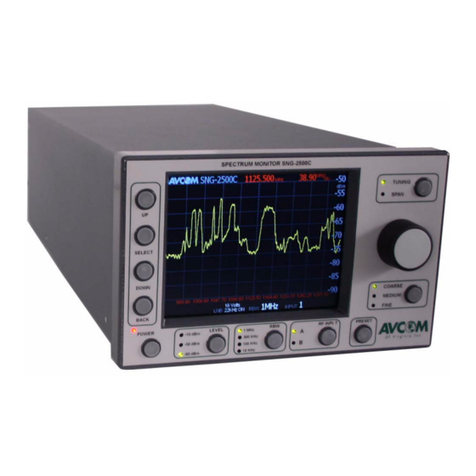
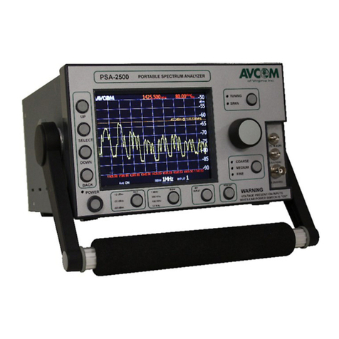
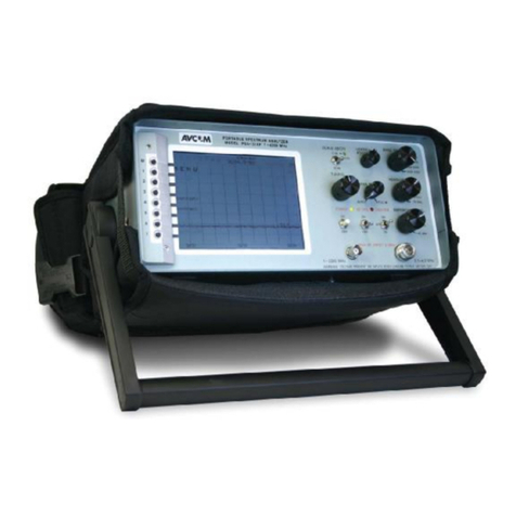
AVCOM PSA-65C Operating instructions

AVCOM®
PSA-65C
PORTABLE SPECTRUM ANALYZER
PreliminaryOperating Instructions
500 Southlake Blvd., Richmond, VA.23236
Phone(804)794-2500 / Fax(804)794-8284

PreliminaryOperating InstructionsforAVCOM's
PSA-65CPORTABLE SPECTRUM ANALYZER
Whetheryouareatechnicianor engineerwhoisthoroughlyversedintheapplications ofa
spectrumanalyzer or someone who has never used one, you will be surprised by the ease of
operationandversatilityofthePSA-65C.Usuallywhenaspectrumanalyzerispurchased,the
customer has a specificapplication inmind however, as you becomemore familiar with the
characteristicsandperformanceofthePSA-65C,thenumberofapplicationswillincrease.The
lightweight,battery orline operated PSA-65CportablespectrumanalyzerfromAVCOMisthe
perfectinstrumentforfieldtestingofRFsystems,classroominstruction,satellitesystemalign-
ment,electroniccountermeasures,cableTVmaintenance,cellularandproductionuse.
TABLEOFCONTENTS
Introduction
Section 1 Accessories &Options
Section 2 Operation
Section 3 SpecificationsandTechnical Data
Section 4 ApplicationNotes
Section 5 Reference Material
Section 6 OtherAVCOM Products

IMPORTANT
READ CAREFULLYBEFORE USING INSTRUMENT
GENERAL SAFETY
Your PSA-65Cisconnected to an AC power source (110, 220 or 240 VAC depending
on model)and itisimportant that all components of your test bench are properlygrounded to
reduce the possibility of electricalshock.
Use properlygrounded electricaloutlet or extension cord.
Do not cut grounding pin fromline cord plug.
Use fuses of correct amperage.
Disconnect AC line cords when working inside electricalappliances or instruments.
Do not service equipment alone - Work with someone who can administer help and
first aid.
Personsworking with line voltagesshouldbe trained inand capableof performingfirst
aid and resusitation techniques.
IMPORTANTCAUTIONS
DonotcoupletheinputofthePSA-65CtohighpowerRFsourcessuchaswalkie-talkies,
CB radios, transmitters, etc. Signal levelsinexcess of +15 dBmcan damage the sensitive
mixers in the instrument resulting in otherwise unnecessary expense and repairs.
HANDLE WITHCARE -The PSA-65CPortableSpectrumAnalyzer isaprecision
instrumentdesignedfornormaloperatingandhandlingconditions. Itshouldbeprotectedfrom
abuseas dropping, throwingor other roughhandling. When being transportedinavehicleor
shipped, the PSA-65Cmust be cushioned and protected against shock and vibration.

SECTION 1
PSA-65CACCESSORIES
A.LPA-1000ALOG PERIODIC ANTENNA 1-1
B. RFP-24 RFPREAMPLIFIER 1-2
C. DCP-20 DC POWER INSERTER 1-2
D. FREQUENCYEXTENDERS 1-4
E. AUXILLARY JACK PIN IDENTIFICATION 1-5
F.AVSAC(Carrying Case) 1-5
G.OVERLAYS 1-6
H. BROADBAND NOISE GENERATOR 1-6
PSA-65COPTIONS
A.FMDEMODULATOR 1-8
B. 10 KHZRESOLUTION BANDWIDTHFILTER 1-8
C. OSCILLOSCOPE INTERFACE 1-9
D. AMDETECTOR 1-10

SECTION 2
PSA-65COPERATION
A.FRONTPANELFUNCTIONS 2-1
B. USER FAMILIARIZATION &PRELIMINARY
CHECKOUT 2-5
C. HORIZONTALPOSITION CONTROL 2-7

SECTION 3
PSA-65CSPECIFICATIONS
&
TECHNICAL DATA
A.PSA-65CSPECIFICATIONS 3-1
B. PSA-65CBLOCK DIAGRAM 3-2
C. SPARE PARTSLIST 3-3
D. BAILHANDLEASSEMBLYSEQUENCE 3-4
E. CORD WRAPPROCEDURE 3-4
F.BATTERY PACK REPLACEMENT
PROCEDURE 3-5
G.PROCEDURES FOR INSTALLING EPROMS 3-6
H. LIMITED WARRANTY 3-7

SECTION 4
PSA-65CAPPLICATIONS

SECTION 5
REFERENCE MATERIAL

SECTION 6
OTHER AVCOMPRODUCTS

21
AVCOM's PSA-65C
1
POWER 9
SPAN
18
REFERENCE
LEVEL
12
TUNING
16
VERT
SENS
15
VERTICAL
POSITION
17
SWEEP
RATE
8
RF INPUT
.1-1250MHz
10
VAR
SPAN
13
FINE
TUNE
2
BATCHG 3
INTENS 4
HORIZ 5
AUDIO
OUT
6
AUDIO
DEMOD
7
AUX 20
AM-FM
SELECTOR
11
ZERO
SPAN
14
MULTI-FUNCTION
LIQUID CRYSTAL
DISPLAY
19
DIGITAL
FREQUENCY
LOCK

22
FRONTPANELFUNCTIONS
1. POWER
POWERSWITCH- ThePOWERswitchhasthreepositions;BATteryoperation,STandBY,
andLINEoperation.
BAT-Turnsinstrumentonandinstrumentispoweredbyinternalrechargeablebatterypack.
NOTE:AnINTERNAL/EXTERNALbatteryswitchandEXTERNALPOWERjackarelocated
onrearpanelofthePSA-65C. Whenplacedto"EXTERNAL"position,anexternal11.5-15
VDCpowersourcecanprovidepowertothePSA-65C. Thisalsochargesinternalbatteries.
STBY -Amber LED isilluminated ifline cord isconnected to AC power source. Instrument is
functionallyoffalthoughpowerispresentinsidechassis. NOTE:Inthisposition,thebattery
charger isoperationaland the internalbattery pack can be re-charged.
LINE-Turns thePSA-65Con. All powerisbeing providedbythe AClinesource.
2. BATCHG/MON
TheBATtery CHarGerisconnected tointernalbattery packwhen thisswitchisinthe"ON"
position. AnamberLEDisilluminatedwhilebatterychargerison.NOTE:Forproperbattery
chargeroperation,thePSA-65CPOWERswitchshouldbeinthe"STBY"position. Thenthe
PSA-65C will be recharged to approx.80%in6hours and 100%when left on charge
overnight.
NOTE: When BATCHG and PSA-65C are on, the lower line of LCD display will indicate
batteryvoltage.
3. INTENS
TheINTENSitycontrolsetstheintensityofthetrace.
4. HORIZPOSITION - (Horizontal Calibration isfactory set, however the unitcan still be
calibrated inthe field by using atuning tool to turn the recessed HORIZPOSITION control
pot).See horizontalcalibrationinuserfamiliarizationsection.
TheHORIZontalPOSITIONcontrolpositionsthesweephorizontallyonthescreen. When
properlyadjusted,asignallocatedatthecenterofthescreenwillremaininthecenterofthe
screeninanySPANposition.
5. AUDIOOUTJACK
DrivesalowimpedanceearphoneorspeakerwhentheAUDIODEMODulatoristurnedon.
Usingthisjackdisconnectstheinternalspeaker.
6. AUDIODEMOD
ThiscontrolactivatestheAUDIODEMODulatorcircuitandcontrolstheoutputlevelofthe
demodulatedaudiooutput. NOTE:AudiocanbeheardanytimetheAM-FMselectorisinthe
AMposition or when the ZERO SPAN toggleswitch isplaced ineither the "AUDIO" or
MOMENtary"positionintheFMmode.

23
7. AUXILARY CONNECTOR
ThisAUXiliarysocketsupportspresentandfutureoptionalaccessoriesforthePSA-65C.
8. RFINPUT
ThisBNC connectoraccepts RFsignalsto signalstobe observed fromless than1MHz to
greaterthan1250MHz.
9. SPAN
TheSPANcontrolsetsthescaleofthehorizontalsweeppresentationfrom1250MHz(125
MHz/div)to2MHz(.2MHz/div). ThiscontrolalsoautomaticallyselectstheoptimumIF
resolutionfilter.
10.VARSPAN
TheVARiableSPANcontrolreducesthewidthofthespectrumbeingdisplayedforcloser
signalexaminationandenhancesamplitudeaccuracy.
11.ZERO SPAN
ZEROSPANinstantlyplacestheanalyzerintothezerospanmodeandactivatestheFMaudio
demodulatorforconvenientsignalmonitoring.
AUDIO-(Upwardpositionandswitchremainsinthispositionuntilmanuallypushedagain).
ThispositionswitchesontheFMdemodulatorcircuituntiltheZEROSPANswitchisreturned
totheNORMalposition.
NORM-ThisisthenormalpositionoftheZEROSPANswitchwhennotmonitoringaudio
signals.
MOMEN-Thisisamomentaryswitchpositionthatinstantlyplacestheanalyzerintothezero
spanmodeandactivatestheFMaudiodemodulatorforconvenientsignalmonitoring.
12.TUNING
Thismulti-turncontroladjuststhecenterfrequencyoftheanalyzersothatsignalsofinterest
appearatthecenterofthedisplay.ThecenterfrequencyisalsodisplayedbytheLCDdisplay.
13.FINE TUNE
FINETUNEallowsforfineadjustmentofthecenterfrequency.Greateradjustmentrangeison
theleftsideofthecontrol(-)andfineradjustmentrangeisontherightsideofthecontrol (+).
14.MULTI-FUNCTIONBACKLITLCDDISPLAY
ThenewmicroprocessorallowsthemultifunctionLCDtoshowcenterfrequencyoftheCRT,
span setting in MHz/Div, and the start and stop frequencies of the sweep. The CENTER
FREQUENCY isdisplayed by either 4or 5digits that permits frequency measurements
accurateto100KHz. NOTE:Foraccuratefrequencymeasurements,thePSA-65Cmustbe
inZEROSPAN.Thestartandstopfrequenciesofthesweeparedisplayedwhentheon-screen
bandwidthislessthan270MHzor27MHz/Div.

24
15.VERTICALPOSITION
Controlsthepositionofthesweep.
TOSET:Withnosignalpresent,the"REFERENCELEVEL"switchsetto0dBm,theSPAN
controlset to 1MHz/div, and the VARSPAN controltuned to the FULL position, adjust the
sweeptobecenteredbetweenthetwosmall"tic"markslocatedbetween-60and-70dBmat
thebottomofthedisplay. Donotreadjustforanyotherreferencelevel.
16.VERTICALSENSITIVITY
Usedtoselectverticalamplitudesensitivityofeither10dBm/divor2dBm/div. Normallythis
switchshouldbeinthe"10dBm/div"position. The2dBm/divismosthelpfulwhenobserving
verysmallsignals. Readjustmentofverticalpositionisnormallyrequired.
17.SWEEP RATE
SWEEPRATEcontrolsthespeedofthehorizontalsweepacrossthe CRTdisplay. For
generalobservation,asweepratejustfastenoughthat"traceflicker"disappearsshould
beused. Foraccurateamplitudemeasurementsthesweeprateshouldbesettotheslowest
rate. Generally,thesweeprateshouldnotbesettothefastestrate(fullyclockwise).
18 REFERENCE LEVELdBm/dBmv
TheReferenceLevelcontrolestablishestheamplitudecalibrationforthedisplay. Whenset
atthe0dBmposition,withthescaleswitchinthe10dB/DIVposition,signalspeakingatthe
2ndlinefromthetop,the-10dBm/+49dBmvline,wouldhaveastrengthoramplitudeof-10
dBm/+49dBmv,signalspeakingatthe-20dBm/+29dBmvlinewouldhaveasignalstrength
of -20 /+29 dBmv, dBmand so on.
WhentheReferenceLevelcontrolissetto-20dBmtheverytoplinerepresentsanamplitude
of-20dBm/+29dBmvandthesecondlinedownwouldbe-20dBmminus10or-30dBm(+29
dBmvminus 10 equals+19 dBmv) subtract 10 for each line downto get the signal level
representedbythatline.
Thesameistrueforthe-40dBmpositionexceptthat-40dBm/+9dBmvsignalswouldbeat
thetopline. Thisisthemostsensitivepositionandsignalsasweakas-90dBmcanbeseen.
19.DIGITALFREQUENCY LOCK
TheDigitalFrequencyLock(DFL)isamicroprocessorfunctionthat preventsanalyzerdrift
andishelpfulwhenmonitoringadiscretesignal.Typicallockrange±100KHz.Lockisnormally
onatstart-up,pushFREQLOCKbuttontoturnoff. AflashinglockLEDindicateslockcircuit
isactive. LEDilluminatedindicatesfrequencyislocked.
20.AM-FMSELECTOR SWITCH
The AM-FMSELECTOR SWITCH activates either the AMor FMdemodulator.

25
PSA-65C USER FAMILIARIZATION
AND
PRELIMINARY CHECKOUT
Itis very important that the spectrum analyzeris not storedinfreezingtemperatures.
Operationcanalsobeaffectedbycoldorfreezingtemperatures. Coldbattery capacity
is lower,perhapsonly30%capacity available.
Whenoperatinginbattery mode, turn off thespectrum analyzerwhenbattery voltage
falls to11.4 volts (as readwithBattery Monitorswitch), notdoingsowill decrease
capacity.
BATTERY PACK CHARGING/CARE
IMPORTANT -Charge batteryaminimumof three hours beforeoperation on battery. 80%or
morechargewilloccuraftersixhoursofcharge.
1. PlacePOWERswitchintoSTBYposition.
2. PlugPSA-65Cintoagroundedoutletofcorrectvoltage.
NOTE:AmberSTBYLED isilluminated.
3. SetINT/EXTswitchonrearpanelto"INT",forINTernal.
4. TurnBATCHGto"ON"position.
NOTE:AmberLED isilluminated.
5. Rechargingtimewillvarydependingonthedischargestateofthebattery. Afullydis-
chargedbatterywillrechargein8hours.
NOTE: Anexternalsetof 12voltbatteries maybe rechargedviatheDC jack. Outputof the
DCjack isabout 1/2 ampat 13to 15 voltswhen the internalcharger isoninthe EXT
position.
BATTERY RECHARGING OR OPERATING FROM AN EXTERNALCHARGING
SOURCE.
1. PlugtheDCAUTOadaptercableintothe DCInputJack.
2. SetINT/EXTswitchonrearpanelto"EXT".
3. Connectiontocaradaptershouldonlybemadewithcarenginerunning.
4. PlugtheDCAUTOadapter cableintothecar's12 voltsocket.
NOTE: Recharging current can be as high as 4ampsat 13 to 15 volts. Keep afewspare 4
ampfusesfortheadapteror analyzerwithyouincase ofneed. Thespectrumana
lyzercanbeoperatedoffany externalDCsource(centerpinpositive)between11.5
and 15 volts DC.

26
INITIALTURN-ON &SETUP
1. TurnPOWERswitchto"LINE"andsettheINTENSitycontroltoapprox.80%offully
clockwiseposition.
2. CentertheVERTICALPOSITIONcontrol.
After30seconds,atraceshouldappearonthescreen.
3. Setuptheanalyzercontrolsasfollows:
REFERENCE LEVEL to 0 dBm
SPANcontrolto125MHz/div.
VARSPANcontroltoFULLposition(Fullyclockwise)
SWEEP Rate to 3o'clock position.
VERTICALSENSITIVITYto10dB/div.
ZEROSPANtoggleswitchtotheNORMalposition.
4. Atthistimeasweepshouldbedisplayedonscreen withalargeverticalspike(zero
frequency)atthefarleftsideofthedisplay. NOTE:ThislargesignalisZEROFREQUENCY
and isnormalfor allspectrumanalyzers. (The first LO frequency isequalto thefirst IF
frequencyatthatpoint).
VERTICALCALIBRATION
1. Verticalcalibrationisveryimportantforaccurateabsoluteamplitudereadings.SetSPAN
Switchto1MHz/DIVandsetREFLEVELSWto0dBm.AdjusttheVERTICALPOSITION
controlsothatthehorizontalbaselineiscenteredbetweenthe"Tic"marksbetween-60
amd-70dBm.Theverticaldeflectionisnowcalibratedwiththetopgridlineofthedisplay
equalinamplitudetothesettingofthe REFERENCELEVELcontrol.
NOTE: Oncecalibrated,donotreadjustVERTPOSwhenusingotherSPANSettingsor
REFERENCE LEVELS.
HORIZONTALCALIBRATION-(HorizontalCalibrationisfactoryset,howevertheunitcanstill
be calibrated inthe field by using atuning tool to turn the recessed HORIZPOSITION
control pot).
1. Positionthe VAR SPANcontrolat FULLand using thetuning control,place asignalin
thecenterinthedisplay.Thesignalcanbeanoff-the-airsignal(setREFLEVELto40dBm
formaximumsensitivityandconnectasimpleantennatoRFINPUT)orthezerofrequency
spike. "Expand" the signalspike by rotating the VAR SPAN controlcounter
clockwise. The signalspike may move to the right or to the left. Adjust the TUNING
controlto keep the signalspike centered inthe display until the VAR SPAN controlis
almostfullycounterclockwise. ThenrotatetheVARSPANcontrolclockwisebackto
FULL.IftheHORIZPOSITIONneedsadjustment,thesignalspikewillbedisplacedtothe
leftortotherightofthecenterofthegraticule. AdjusttheHORPOScontroltoplacethe
signalback inthe center of the screen. You may want to repeat thisprocedure and to
performitatnarrowsweepwidthsformaximumaccuracyofthefrequencyreadout.

27
CONCLUSION
1. NotethepositionoftheVERTICAL,HORIZontal,andINTENSitycontrolssothePSA-65C
canbeputintoservicerapidlythenexttimeitisused.
2. ThiscompletestheUserFamiliarizationandPreliminaryCheckoutofthePSA-65C.

31
PSA-65CSPECIFICATIONS
FREQUENCYCOVERAGE SENSITIVITY
1MHz to 1250 MHz inone sweep. -95dBm
200 KHzto1000 MHzwhen optional10 KHzRes B.W. installed. AMPLITUDEACCURACY
RESOLUTIONBANDWIDTH +2 dB typical
AutomaticallyselectablebySpanControl FREQUENCYDISPLAY
a) 3MHz ResB.W.(set span at 125 MHz/Div) 2x16 digitbacklitLCD
b) 1MHz ResB.W.(set span at 50 MHz/Div)
c) 300 KHz ResB.W.(set span at 10 MHz/Div) DIMENSIONS
d) 150 KHz ResB.W.(set span at 5MHz/Div) 11.5"Wx5.5"H x13.5"D
e) 75 KHz ResB.W.(set span at 1or .2 MHz/Div)
f)Optional10 KHz ResB.W.(set span at .2 MHz/Div) WEIGHT
Extends lower frequency range to approximately 200 KHz 18 Lbs/ 8.18 Kg
Note: ANarrowBand Cavity Oscillator isswept for .2 MHz/ POWER REQUIREMENTS
Divspansothat signalscan be observed with lowoscillator External115 VAC 60Hz /12 VDC
noisecontribution. Internal12VGelCellBattery
220/240Voltmodelsavailable
REFERENCELEVELS
+20, 0, -20, -40 dBm/+69, +49, +29, +9dBmv ACCESSORIES
1.25-2.50GHzFrequency Extender
INPUTCONNECTOR 2.50-3.75GHzFrequency Extender
Type BNC (BNC to Fadapter included) 950-1450MHzFrequencyExtender
TypeN(optional) 3.7-4.2GHz FrequencyExtender
1.7-2.7GHz FrequencyExtender
DISPLAY DCP-20 DC Power Inserter / Block
10horizontalgraticuleDivisions(frequency) x7vertical AVSAC Carrying Case
graticuleDivisions(amplitude). EachverticalDivision LPA-1000 Log PeriodicAntenna
equals 10 dB or 2dB. RFP-24Preamplifier
BNG-1000 BroadbandNoiseGenerator
ADA-10A Analyzer Display Adapter
VDM-2FM VideoDemod/AMVideo Conv.
MTG-1000AMicrowaveTrackingGenerator
OSA-20AOscilloscopeAdapter
OPTIONS
10 KHz Resolution Bandwidth

32
Horizontal
& Vertical
Deflection
Low Pass
Filter
1500 MHz
4 Cavity
Filter
RF
Attenuator
REFERENCE
LEVEL
Yoke CRT
High
Voltage
HORIZ
POSIT.FRONT PANEL
VERT.
POSIT. INTENS
dB/DIV
FRONT PANEL
Cavity
Oscillator
1489.205
Cavity
Oscillator
Calibration
0-1250
MHz
VCO
1.5-2.75GHz
Ramp
Generator
FRONT PANEL
SWEEP VAR
SPAN SPAN
Ctr. Freq.
TUNING
Prescaler Frequency
Counter
LCD
DOWNCONVERTER ASSEMBLY
Log
Amp
Attenuator
PCB
PSA-65C BLOCK DIAGRAM
FM
Demod
FRONT PANEL
Speaker
10.7MHz
Filter
3-4MHzBW
10.7MHz
Flter
10KHzB.W
(Optional)
HORIZONTAL RAMP BLANKING PULSE
10.7MHz
VariableBW
Filter
Audio Vol
ON/OFF AM
Detector

33
BAILHANDLEASSEMBLYSEQUENCE
The bail handlefriction knob must be assembled inthe order shownbelow.The order of
partsare (1)knob,(2) stainlesssteelwasher,(3) teflon washer,(4)bail handle, (5) aluminum
spacerand(6)rubberwasher.
There are two of these assemblies mounted to either side of the chassis. If they are not
attachedinthisway,the handlemaynotfunctionproperlyasapropstand.
CORD WRAPPROCEDURE
1.Wrappowercordinacounterclockwise directionaroundcordguides.Only topandbottom
hooks ofcord guides are tobe used.
2.Tuckplugbehindoutermoststrandsofwrappedcord.
PSA-65C -REARPANELVIEW
ALUMINUM SPACER
RUBBER WASHER TEFLON WASHER
STAINLESS STEEL WASHER
KNOB
WRAP COUNTERCLOCKWISE

34
PSA-65C BATTERY PACK REPLACEMENTPROCEDURE
Read thefollowing instructions intheirentiretybefore attempting battery replacement.
1. Unplug AC cord from unit.
2. Remove battery fuse, set aside to avoidloss.
3. Remove the four screwsfrombattery access cover found on the bottomof the unit.
CAUTION: Care shouldbe used so as not to let both terminalsof abattery touch the
bracket at the sametime. Before removing oldbatteries, their polarity should
be noted.
FOR REMOVAL -ALWAYS DISCONNECTTHE BLACK (NEGATIVE) LEAD FIRST!
WHENINSTALLING-RECONNECTTHE BLACK(NEGATIVE)LEADLAST!
4. Allow batteries to slowly drop out of cavity.
Note: Do not try to pull more than six inches of wire leads frombattery wire exitpoint.
For additionalclearance, the surrounding battery bracket and rear panelscrewscan
beloosenedslightly.
5. Carefullyobserve orientation of battery terminalsand wiring when removing battery set.
6. Disconnect wires by sliding crimpconnectors off battery terminals. Againnote location of
disconnected wires for reference inreassembly.
7. Make sure plasticinsulation sheet inside of cavity isinplace, rewire and install new
batteries facing inthe samedirection as oldbatteries.
TIP: Taping the batteries together, above and below,makes iteasier to handlebatteries.
8. Replace the cover and hardware and tighten all screws.
9. Reinstall the battery fuse.
10. Test for proper battery operation.
Table of contents
Other AVCOM Measuring Instrument manuals
Popular Measuring Instrument manuals by other brands

Sensitech
Sensitech TempTale 4 Instructions for use

THEIS
THEIS DTC 5.1 instruction manual

Kett
Kett KB-270 operating manual

Alpha Moisture Systems
Alpha Moisture Systems SADPminiEx instruction manual
Dante
Dante Inovonics 541 Installation & user guide

Horiba Scientific
Horiba Scientific LAQUA F-73G Setup and lnstruction manual
BLADDERSCAN
BLADDERSCAN BVI 3000 Operation & maintenance manual
PCB Piezotronics
PCB Piezotronics IMI SENSORS ICP 625B11 Installation and operating manual

Vernier
Vernier Conductivity Probe manual
ROM Elektronik
ROM Elektronik ESM-2 manual
Campbell
Campbell 03002 product manual

horiba
horiba HEMAPREP RAB316AEN user manual
