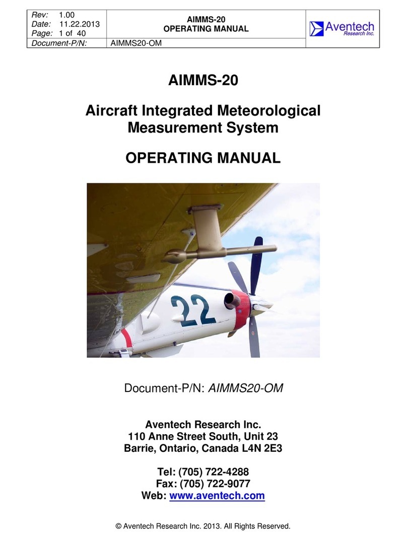
Aventech AIMMS-20 User manual

Rev: 1.00
Date: 11.11.2013
Page: 1 of 48
AIMMS-20
INSTALLATION MANUAL
Document-P/N: AIMMS20-IM
© Aventech Research Inc. 2013. All Rights Reserved.
AIMMS-20
Aircraft Integrated Meteorological
Measurement System
INSTALLATION MANUAL
Document-P/N: AIMMS20-IM
Aventech Research Inc.
110 Anne Street South, Unit 23
Barrie, Ontario, Canada L4N 2E3
Tel: (705) 722-4288
Fax: (705) 722-9077
Web: www.aventech.com

Rev: 1.00
Date: 11.11.2013
Page: 2 of 48
AIMMS-20
INSTALLATION MANUAL
Document-P/N: AIMMS20-IM
© Aventech Research Inc. 2013. All Rights Reserved.
Issued
Date Name Signature Function
31.10.2013 Bruce H. Woodcock DE
Checked
Date Name Signature Function
08.11.2013 Bruce H. Woodcock DE
Approved
Date Name Signature Function
11.11.2013 Bruce H. Woodcock HD
Customer Approval (as required)
Date Name Signature Function
Table of Functions
CUST Customer
DE Design Engineer
HD Head of Design Engineering
PM Production Manager
QM Quality Manager

Rev: 1.00
Date: 11.11.2013
Page: 3 of 48
AIMMS-20
INSTALLATION MANUAL
Document-P/N: AIMMS20-IM
© Aventech Research Inc. 2013. All Rights Reserved.
NOTICES
WARRANTY
Aventech Research Inc. products are warranted to be free from defects in material and
workmanship under normal use and service for a period of one year beginning on the
date of shipment. This warranty extends only to the original buyer or end-user customer
of an Aventech Research Inc. authorized reseller. This warranty does not apply to any
product which, in Aventech Research Inc’s opinion, has been misused, altered,
neglected, contaminated, or damaged by accident or abnormal conditions of operation
or handling.
Aventech Research Inc’s warranty obligation is limited, at Aventech Research Inc’s
option, to refund of the purchase price, free of charge repair, or replacement of a
defective product which is returned within the warranty period.
To obtain warranty service, return the product to the nearest Aventech Research Inc.
authorized reseller, or direct to the address provided below:
Aventech Research Inc.
110 Anne Street South, Unit 23
Barrie, Ontario, Canada L4N 2E3
Tel: (705) 722-4288
Fax: (705) 722-9077
Shipping costs to Aventech Research Inc. are the responsibility of the end customer
(FOB Destination). Aventech Research Inc. assumes no risk for damage in transit.
Following warranty repair, the product will be returned to Buyer, transportation prepaid
(FOB Destination). If Aventech Research Inc. determines that failure was caused by
neglect, misuse, contamination, alteration, accident, or abnormal condition of operation
or handling, including overvoltage failures caused by use outside the product’s specified
rating, or normal wear and tear of mechanical components, Aventech Research Inc. will
provide an estimate of repair costs and obtain authorization before commencing the
work. Following repair, the product will be returned to the Buyer transportation prepaid
and the Buyer will be billed for the repair and return transportation charges (FOB
Shipping Point).
Aventech Research Inc. warrants that product firmware will operate substantially in
accordance with its functional specifications. Aventech Research Inc. does not warrant
that firmware will be error free or operate without interruption.

Rev: 1.00
Date: 11.11.2013
Page: 4 of 48
AIMMS-20
INSTALLATION MANUAL
Document-P/N: AIMMS20-IM
© Aventech Research Inc. 2013. All Rights Reserved.
The material contained in this document is provided “as is,” and is subject to being
changed, without notice, in future editions. Further, to the maximum extent permitted by
applicable law, Aventech Research Inc. disclaims all warranties, either express or
implied, with regard to this manual and any information contained herein, including but
not limited to the implied warranties of merchantability and fitness for a particular
purpose. Aventech Research Inc. shall not be liable for errors or for incidental or
consequential damages in connection with the furnishing, use, or performance of this
document or of any information contained herein. Should Aventech Research Inc. and
the user have a separate written agreement with warranty terms covering the material in
this document that conflict with these terms, the warranty terms in the separate
agreement shall control.
THIS WARRANTY IS BUYER'S SOLE AND EXCLUSIVE REMEDY AND IS IN LIEU OF
ALL OTHER WARRANTIES, EXPRESS OR IMPLIED, INCLUDING BUT NOT LIMITED
TO ANY IMPLIED WARRANTY OF MERCHANTABILITY OR FITNESS FOR A
PARTICULAR PURPOSE. AVENTECH RESEARCH INC. SHALL NOT BE LIABLE
FOR ANY SPECIAL, INDIRECT, INCIDENTAL, OR CONSEQUENTIAL DAMAGES OR
LOSSES, INCLUDING LOSS OF DATA, ARISING FROM ANY CAUSE OR THEORY.
COPYRIGHT
© Aventech Research Inc. 2013. No part of this manual may be reproduced in any form
or by any means (including electronic storage and retrieval or translation into a foreign
language) without prior agreement and written consent from Aventech Research Inc. as
governed by Canadian and international copyright laws.

Rev: 1.00
Date: 11.11.2013
Page: 5 of 48
AIMMS-20
INSTALLATION MANUAL
Document-P/N: AIMMS20-IM
© Aventech Research Inc. 2013. All Rights Reserved.
RECORD OF REVISIONS
Date Issue Page Paragraph Firmware
Revision Comments
31.10.2013 1.00 All All Preliminary Draft
11.11.2013 1.00 All All Release

Rev: 1.00
Date: 11.11.2013
Page: 6 of 48
AIMMS-20
INSTALLATION MANUAL
Document-P/N: AIMMS20-IM
© Aventech Research Inc. 2013. All Rights Reserved.
TABLE OF CONTENTS
1 INTRODUCTION .....................................................................................................................8
2 SYSTEM COMPONENT DESCRIPTIONS..............................................................................9
2.1VerifytheListofSuppliedComponents..............................................................................................9
2.2AirDataProbe(ADP).........................................................................................................................10
2.3InertialMeasurementUnit(IMU).....................................................................................................12
2.4GPSPhaseModule(GPS)..................................................................................................................12
2.5CentralProcessingModule(CPM)....................................................................................................13
2.6Communications...............................................................................................................................14
3 INSTALLATION INSTRUCTIONS .........................................................................................15
3.1AirDataProbe(ADP).........................................................................................................................15
3.1.1Under‐WingMountAirDataProbe...........................................................................................15
3.1.2Sting‐MountAirDataProbe.......................................................................................................16
3.2InertialMeasurementUnit(IMU).....................................................................................................18
3.3GPSPhaseModule(GPS)..................................................................................................................20
3.3.1GPSAntennas.............................................................................................................................20
3.3.2GPSPhaseModule.....................................................................................................................21
3.4CentralProcessingModule(CPM)....................................................................................................21
3.5Electrical/CommunicationsWiring..................................................................................................22
3.5.1GPSCoaxialAntennaCables......................................................................................................22
3.5.2ControllerAreaNetwork(CAN)Cables......................................................................................22
3.5.3PowerInputCable......................................................................................................................23
3.5.4RS‐232SerialCommunicationsCable........................................................................................23
4 GROUND TEST PROCEDURE.............................................................................................24
4.1ApplicationofPowertotheSystem.................................................................................................24
4.2AirDataProbe(ADP).........................................................................................................................24
4.3InertialMeasurementUnit(IMU).....................................................................................................24
4.4GPSPhaseModule(GPS)..................................................................................................................24
4.5CentralProcessingModule(CPM)....................................................................................................25

Rev: 1.00
Date: 11.11.2013
Page: 7 of 48
AIMMS-20
INSTALLATION MANUAL
Document-P/N: AIMMS20-IM
© Aventech Research Inc. 2013. All Rights Reserved.
5 INSTRUCTIONS FOR CONTINUED AIRWORTHINESS (ICA) ............................................26
5.1Pre‐FlightChecks...............................................................................................................................26
5.2OperationalChecks...........................................................................................................................26
5.3AircraftMaintenanceSchedule........................................................................................................26
5.4Troubleshooting................................................................................................................................27
5.5ServiceRemoval................................................................................................................................28
APPENDIX A: AIMMS-20 COMPONENT CAD DRAWINGS......................................................30
A.1Under‐WingAirDataProbe(ADP)....................................................................................................31
A.2StingMountAirDataProbe(ADP)....................................................................................................34
A.3InertialMeasurementUnit(IMU).....................................................................................................37
A.4GPSPhaseModule(GPS)andAntennas...........................................................................................40
A.4.1SensorSystemsS67‐1575‐39GPSAntennaDatasheet.............................................................43
A.4.2ANTCOM3G15A‐XT‐1GPSAntennaDatasheet........................................................................44
A.5CentralProcessingModule(CPM)....................................................................................................45
A.6AIMMS‐20WiringDiagram...............................................................................................................48

Rev: 1.00
Date: 11.11.2013
Page: 8 of 48
AIMMS-20
INSTALLATION MANUAL
Document-P/N: AIMMS20-IM
© Aventech Research Inc. 2013. All Rights Reserved.
1 INTRODUCTION
The Aventech Research Inc. AIMMS-20 (Aircraft Integrated Meteorological
Measurement System) is an integrated, turn-key system for measuring accurate,
real-time meteorological data on airborne platforms. The meteorological data set
includes temperature, humidity, three-dimensional winds (speed, direction and
vertical) and turbulence. The data generated by the system is broadcast in real-time
via an RS-232 serial communications link to either a GPS navigation system or data
acquisition system.
This document provides a general description on how to install the AIMMS-20 on an
airframe and engineering information to support the subsequent approval process
with the appropriate certifying body.
Please note that the AIMMS-20 does not carry a Supplemental Type Certificate
(STC) and as such the customer is responsible for obtaining the required
airworthiness approval and / or certification for their aircraft category in order to
operate with the system on-board.

Rev: 1.00
Date: 11.11.2013
Page: 9 of 48
AIMMS-20
INSTALLATION MANUAL
Document-P/N: AIMMS20-IM
© Aventech Research Inc. 2013. All Rights Reserved.
2 SYSTEM COMPONENT DESCRIPTIONS
The AIMMS-20 system consists of four modules in total, an Air Data Probe (ADP)
which is mounted external to the aircraft, an Inertial Measurement Unit (IMU), a
GPS Phase Module (GPS) and a Central Processing Module (CPM). The following
section of this manual lists the system components that should have arrived in your
shipment and describes each of them in order to familiarize you with the system.
2.1 Verify the List of Supplied Components
The first thing you will want to do is verify that you have received the following items
with your AIMMS-20. If anything is missing, please contact your approved reseller
or Aventech Research Inc. directly.
One Air Data Probe (ADP) [Under-Wing or Sting Mount Version].
One Inertial Measurement Unit (IMU).
One GPS Phase Module (GPS).
One Central Processing Module (CPM).
Two 3.5” diameter GPS antennas.
One cable set (3 CAN, 1 Power, 1 Serial).
This Installation Manual.
A copy of the AIMMS-20 Operating Manual.
A copy of the aimcfg PC-based software utility.
Figure 1: AIMMS-20 Under Wing Mount Components

Rev: 1.00
Date: 11.11.2013
Page: 10 of 48
AIMMS-20
INSTALLATION MANUAL
Document-P/N: AIMMS20-IM
© Aventech Research Inc. 2013. All Rights Reserved.
Figure 2: AIMMS-20 Sting-Mount System Components
2.2 Air Data Probe (ADP)
The Air Data Probe is mounted external to the aircraft and is the component of the
AIMMS-20 which measures the three-dimensional flow vector relative to the aircraft
frame of reference, Outside Air Temperature (OAT) and Relative Humidity (RH) and
turbulence. Having knowledge of the atmospheric temperature allows the system to
calculate accurate True Airspeed (TAS) which can be subtracted from the total flow
vector to resolve the three-dimensional wind vector relative to the aircraft frame of
reference.
The three-dimensional flow vector is measured using a series of five pressure ports
located on the hemispherical nose the ADP’s measurement boom and a ring of
static pressure ports slightly aft of the measurement boom nose. Using this set of
pressure ports measurement of the barometric, pitot-static, differential angle-of-
attack and differential side-slip pressure measurements can be obtained which
define the three-dimensional flow vector.
OAT and RH measurements are made using a small 0.038” diameter bead
thermistor and thermoset polymer RH sensor respectively. Both sensors are located
in a reverse-flow chamber at the aft end of the probe to protect them from direct
impact with particulates and larger objects in the free stream flow.
With your AIMMS-20 system you will have received one of two Air Data Probe types
depending on the airframe for the planned installation, an under-wing version as
shown in Figure 1 or a sting-mount version as shown in Figure 2.

Rev: 1.00
Date: 11.11.2013
Page: 11 of 48
AIMMS-20
INSTALLATION MANUAL
Document-P/N: AIMMS20-IM
© Aventech Research Inc. 2013. All Rights Reserved.
Figure 3: AIMMS-20 Under-Wing Air Data Probe Installation
Figure 4: AIMMS-20 Sting-Mount Air Data Probe Installation
The under-wing ADP is typically utilized for fixed-wing installations while the sting-
mount ADP is typically utilized in rotary-wing installations. In some cases end users
have also used the sting-mount probe for fixed-wing installations with their own
mounting bracket design.

Rev: 1.00
Date: 11.11.2013
Page: 12 of 48
AIMMS-20
INSTALLATION MANUAL
Document-P/N: AIMMS20-IM
© Aventech Research Inc. 2013. All Rights Reserved.
2.3 Inertial Measurement Unit (IMU)
The IMU is a six-degree of freedom inertial measurement unit consisting of three
MEMS accelerometers and three MEMS rate gyros. Utilizing inexpensive MEMS-
based measurement devices provides a high-accuracy, low cost method of
measuring the dynamic, high-frequency motion of an airborne platform. However,
the compromise is that MEMS-based measurement devices have poorer long term
DC stability. The AIMMS-20 system compensates for this DC instability using a
single-axis GPS carrier-phase system which is described in Section 2.4.
Figure 5: AIMMS-20 Inertial Measurement Unit
2.4 GPS Phase Module (GPS)
The GPS Phase module is a two antenna, single baseline GPS carrier-phase
subsystem. Accurate, DC-stable attitude of the baseline between two GPS
antennae either mounted laterally (wingtip to wingtip) or longitudinally (wingtip to
wingtip or fore / aft) on the airborne platform can be determined using the GPS
carrier-phase measurements from the two GPS receivers located in the module.
Lateral antennae configurations are typically used on fixed-wing aircraft while
longitudinal antennae configurations can be utilized on fixed or rotary wing aircraft.
Although the attitude measurement performed using this technique is stable it is low
frequency (1 Hz). Higher frequency dynamic information is provided by the IMU
described in Section 2.3. The mathematical algorithm used to optimally combine the
two sets of different frequency data is called an Extended Kalman Filter (EKF) and
runs in the firmware loaded in the CPM described in Section 2.5.

Rev: 1.00
Date: 11.11.2013
Page: 13 of 48
AIMMS-20
INSTALLATION MANUAL
Document-P/N: AIMMS20-IM
© Aventech Research Inc. 2013. All Rights Reserved.
Figure 6: AIMMS-20 GPS Phase Module
2.5 Central Processing Module (CPM)
The CPM is essentially the main computational processing center for the AIMMS-20
system. The CPM firmware utilizes the acceleration and rate information from the
IMU and carrier-phase information from the GPS to evaluate the accurate, three-
dimensional attitude for the aircraft using an Extended Kalman Filter (EKF) routine.
In parallel, the three-dimensional winds relative to the aircraft are evaluated using
the air data provided by the ADP. Using the aircraft attitude the wind components
are then transformed to provide the three-dimensional winds in the earth-fixed
frame of reference.
The CPM also acts as the main interface between the aircraft power system and the
AIMMS-20, and the GPS navigation / data acquisition system and the AIMMS-20.
The aircraft power is provided to the AIMMS-20 through the CPM module which
steps the input voltage down +12 VDC and distributes it to the power the balance of
the modules through the Controller Area Network (CAN) cables.
The real-time aircraft state (attitude) and meteorological (temperature, humidity,
wind speed, wind direction and turbulence) data provided by the AIMMS-20 is
broadcast on the second serial port of the CPM as two unique aircraft state and
meteorological packets which can be read by a host computing device such as a
GPS navigation system or data acquisition system.

Rev: 1.00
Date: 11.11.2013
Page: 14 of 48
AIMMS-20
INSTALLATION MANUAL
Document-P/N: AIMMS20-IM
© Aventech Research Inc. 2013. All Rights Reserved.
Figure 7: AIMMS-20 Central Processing Module
2.6 Communications
The four AIMMS-20 modules communicate with each other via a high-speed, digital
serial Controller Area Network (CAN) bus. The four conductor cable connected between
the modules provides power to each of the modules and communication between them.
Communication between the AIMMS-20 and a host computing device (GPS navigation
or data acquisition system) is via a standard RS-232 serial port.

Rev: 1.00
Date: 11.11.2013
Page: 15 of 48
AIMMS-20
INSTALLATION MANUAL
Document-P/N: AIMMS20-IM
© Aventech Research Inc. 2013. All Rights Reserved.
3 INSTALLATION INSTRUCTIONS
3.1 Air Data Probe (ADP)
3.1.1 Under-Wing Mount Air Data Probe
The under-wing version of the AIMMS-20 ADP has an integrated pylon and
mounting flange to accommodate mounting the probe to the lower surface of the
wing (See Figures 3, 8 and 9). Detailed drawings of the ADP and ADP mounting
flange are provided in Appendix A.1.
Typically the probe would be mounted at approximately 75% of the wing semi-span
with the forward edge of the mounting flange sitting on or slightly aft of the main
wing spar. The main consideration in selecting the span-wise mounting location is
that the probe be well clear of any prop-wash in order to obtain accurate wind
measurements. As can be seen in the drawings in Appendix A.1, the 6” by 3” ADP
mounting flange has four 0.266” diameter holes located on a 5.5” by 2.5”
rectangular grid to accommodate four ¼-24 mounting bolts. Figures 3, 8 and 9
provide examples of AIMMS-20 Under-Wing ADP installations.
The weight of the under-wing probe is 3.4 kg or 7.4 lbs and it has a drag coefficient
of 0.002480. Drag force as a function of airspeed is provided in Table 1. Based on
these forces, the installation provider will evaluate whether or not there is sufficient
stringer material to mount the probe directly to the wing skin or on an inspection
panel, or whether a wing skin doubler is required. It is recommended that if a wing
skin doubler is installed that existing rivets in the wing spar be utilized whenever
possible to avoid drilling new holes in the spar structure.
Figure 8: AIMMS-20 Under-Wing Air Data Probe Installation

Rev: 1.00
Date: 11.11.2013
Page: 16 of 48
AIMMS-20
INSTALLATION MANUAL
Document-P/N: AIMMS20-IM
© Aventech Research Inc. 2013. All Rights Reserved.
Figure 9: AIMMS-20 Under-Wing Air Data Probe Installation
True Airspeed Drag Force
m/s knots N lbf
25 48.6 1.0 0.2
50 97.2 3.8 0.9
75 145.8 8.5 1.9
100 194.4 15.2 3.4
125 243.0 23.7 5.3
150 291.6 34.2 7.7
Table 1: Drag Force versus Airspeed for AIMMS-20 Under-Wing ADP
Any mounting installation must allow for a minimum 0.625” diameter hole in the
vicinity of the Controller Area Network (CAN) receptacle on the ADP to
accommodate passing the CAN cable through the wing skin surface so that it may
be plugged into the receptacle.
3.1.2 Sting-Mount Air Data Probe
The sting-mount version of the AIMMS-20 differs from the under-wing mount
version in that the pylon has been eliminated and the electronics embedded in the
pylon have been moved into a 12” longer measurement boom (36” rather than 24”
length). The result is a lighter unit, 3 lbs., which can be mounted far forward on a
helicopter. Although initially designed with helicopter platforms in mind, the sting-
mount ADP has also seen use on fixed-wing airframes. Detailed drawings of the
sting-mount ADP are provided in Appendix A.2.

Rev: 1.00
Date: 11.11.2013
Page: 17 of 48
AIMMS-20
INSTALLATION MANUAL
Document-P/N: AIMMS20-IM
© Aventech Research Inc. 2013. All Rights Reserved.
On rotary wing airframes, the ADP should be mounted as far forward of the
fuselage as possible. The reason for this is to insure that the probe is clear of the
rotor downwash at as low a forward speed as possible as the helicopter moves
forward and the downwash is advected back across the fuselage. The ADP
enclosure has eight integrated mounting holes embedded in its’ enclosure, two sets
of four holes located circumferentially around the measurement boom separated by
six inches, which are tapped to accommodate 10-32 mounting fasteners (see
drawings in Appendix A.2). These tapped holes can be utilized in a customer
designed bracket to mount the ADP on the nose of the helicopter, off of the skid or
on the lower wire cutter if the helicopter is outfitted with a wire strike kit. The
thickness of the mounting bracket components that clamp onto the measurement
boom should be as thin as possible so as to not obstruct flow over the aft end of the
probe. Figures 4, 10 and 11 provide examples of AIMMS-20 Sting-Mount ADP
installations.
The weight of the sting-mount probe is 1.4 kg or 3.0 lbs and it has a drag coefficient
of 0.001972. Drag force as a function of airspeed is provided in Table 2. Based on
these forces, the installation provider can design an appropriate mounting bracket.
Figure 10: Sting-Mount Air Data Probe Installation

Rev: 1.00
Date: 11.11.2013
Page: 18 of 48
AIMMS-20
INSTALLATION MANUAL
Document-P/N: AIMMS20-IM
© Aventech Research Inc. 2013. All Rights Reserved.
Figure 11: AIMMS-20 Sting-Mount Air Data Probe Installation
True Airspeed Drag Force
m/s knots N lbf
25 48.6 0.8 0.2
50 97.2 3.0 0.7
75 145.8 6.8 1.5
100 194.4 12.1 2.7
125 243.0 18.9 4.2
150 291.6 27.2 6.1
Table 2: Drag Force versus Airspeed for AIMMS-20 Sting-Mount ADP
3.2 Inertial Measurement Unit (IMU)
The remaining three modules, the Inertial Measurement Unit (IMU), GPS Phase
Module (GPS) and Central Processing Module (CPM), are all housed in octagonal
fibreglass with 40% graphite filler enclosures. The enclosures measure
approximately 4.75” by 4.75” by 3.0“ dimensionally and have integrated mounting
tabs with 0.25” wide slots at their base to accommodate 10-32 or ¼-28 mounting
hardware. For detailed drawings of the enclosures see Appendix A.3 to A.5.
The IMU is the only other module which is orientation specific. The unit should be
rigidly mounted to the airframe such that the airplane graphic label on its’ lid is
aligned with the direction of flight and the base is as parallel as possible to the
attitude of the aircraft in level flight (gravity vector perpendicular to the base of the
module). If oriented correctly, the LEDs and receptacles on the front face of the
module should be facing forward. While ideally any inertial unit should be mounted

Rev: 1.00
Date: 11.11.2013
Page: 19 of 48
AIMMS-20
INSTALLATION MANUAL
Document-P/N: AIMMS20-IM
© Aventech Research Inc. 2013. All Rights Reserved.
close to the centre-of-gravity of the aircraft, experience from multiple customer
installations has shown that the system functions equally well in multiple locations
on-board the aircraft. As a result, for practical purposes the IMU, GPS and CPM
should be mounted together. Common mounting locations include the forward or aft
baggage compartments, under the pilot and co-pilot’s seats or in a rack in the cabin.
Examples of module installations are presented in Figures 12 and 13.
Figure 12: AIMMS-20 IMU / GPS / CPM Module Installation
Figure 13: AIMMS-20 IMU / GPS / CPM Module Installation

Rev: 1.00
Date: 11.11.2013
Page: 20 of 48
AIMMS-20
INSTALLATION MANUAL
Document-P/N: AIMMS20-IM
© Aventech Research Inc. 2013. All Rights Reserved.
The IMU weighs 0.73 kg or 1.6 lbs
3.3 GPS Phase Module (GPS)
The GPS Phase module consists of two separate components, two GPS antennas
and the module itself.
3.3.1 GPS Antennas
The AIMMS-20 utilizes differential GPS carrier-phase information from two GPS
antennas mounted on the airframe to determine an accurate, stable attitude of the
baseline between them.
The GPS antennas can be mounted on the airframe either laterally, i.e. wingtip to
wingtip, or longitudinally, i.e. fore / aft. A minimum baseline length of at least 5 m
should be maintained if at all possible. Shorter baseline lengths can be utilized with
a small degradation in overall system accuracy. Both orientations can be used on
fixed-wing aircraft where typically the antennas are mounted on the upper surface of
the wingtips or fuselage. Helicopter platforms typically utilize a fore / aft antenna
configuration with the forward antenna mounted on the nose, top of the cabin above
the pilots or on the upper wire cutter, and the aft antenna on top of the vertical
stabilizer / fin. Examples of antenna installations are presented in Figures 14 and
15.
Mechanical drawings and technical specifications for the two 3.0” diameter GPS
antennas that have been supplied with the AIMMS-20 system are provided in
Appendix A.4.
Figure 14: Fore / Aft GPS Antenna Installation
Other manuals for AIMMS-20
1
Table of contents
Other Aventech Measuring Instrument manuals