Aventura Lydie User manual

06.08.17
Lydie
Boat Manual
MAXIMUM CAPACITY: 8 PASSENGERS
Violation Will Result In Suspension of Members Certication and Charter Privileges
BOAT CODE
H36
SLIP
E129
IMPORTANT! Leave All Battery Switches “ON”

24707 Dana Drive, Dana Point, CA 92629
949.493.9493 www.AventuraSailing.com
To: Aventura Charter Member
Re: Lydie - Boat Systems Management
It is imperative that you, as the charterer, understand the important information,
guidelines and crucial system operational procedures in the following Boat Manual
prepared specically for Lydie and if not followed correctly will result in signicant
damage to that system which you the charter will be nancially responsible for its repair
should the damage happen during your charter.
Please be sure you understand how these systems work, that they do work prior
to your charter and if you have any questions to be sure to request one of our eet
operations personnel to meet with you at the boat to go over them.
Enjoy your sailing excursion and thank you for chartering from Aventura!
Sincerely,
James Jones
James Jones
Fleet Operations Manager
Ofce Phone: 949.493.9493
Cell Phone: 949.310.3160

Table of Contents
Motor
Description 1
Control Panel 1
Motor Start 1
Key Switch Safety Features 1
Engine Start 1
Throttle/Shift 1
Power Boost Button 1
Motor Stop 1
Generator
Type 2
Location 2
Starting & Stopping 2
Operation 2
Sea Water Strainer 2
Maintenance 2
Electrical, Electronics and Energy Guide
Energy Gauge 3
Energy Usage Guidelines 3
Electrical Panel 3
Battery Switches 3
Shore Power 3
Sails
Jib 4
Main 4
Tankage
Water Tank 5
Diesel Fuel Tank 5
Holding Tank 5
Empty Holding Tank at Sea 5
General Notes
Head 5
Bilge Pump 5
Refrigerator 5
Stove/Propane 5
Anchor Locker 5
Propeller 5
Inventory
Boat Equipment 6
Aventura Chartering
Policy & Procedures P1-P21

Boat Manual Radio Call Sign Lydie
Make 2012 Hunter
Name Lydie Documentation No. 1239747
Length 35'-06"
Code H36 Beam 12'-04"
Slip E129 Draft 5'-00"
Use this information along with the Discrepancy Report and the Basic Course Syllabus
Hybrid Power
Electric Motor with On-Board Generator for Battery Charging
Description
This Hunter 36e Hybrid has an Elco EP-4000 electric motor that offers the same
amount of thrust as the H-36’s normal 29hp diesel engine. The electric motor offers
the advantages of being truly “green” in that it does not emit any “emissions, noise,
vibrations, heat, or fumes” as it operates solely on battery power with a 7500 watt
on-board generator for convenient and quick charging.
Motor (Engine Compartment) Generator (Port Lazarette)
Control Panel
Motor Start Turn ignition key switch to “ON”. Check battery charge reads 100%.
Key Switch
If the system is turned on with the key switch and the throttle is not in the neutral
position or some other fault is present, the system will not operate, a red light will
ash and the energy gauge panel will identify what the fault is. Also, the system
has built-in overload sensing that prevents electrical damage to the system and will
resume operation once the boat is again aoat.
NOTE: If Key is in the “ON” position for the propulsion system without power
applied - wind instruments will read 2 to 3x actual speed and compass heading will
be off.
Throttle/Shift
Variable Speed
Controller
This is a sealed assembly that provides a smooth variable Forward-Neutral-
Reverse speed control of the system with no hesitation required in going from
Forward to Reverse to Forward.
Power Boost Button
Press to activate spring return button, that when operating the boat at full throttle
forward, will give a power boost to the motor output up to 50% for emergency
situations. This allows the skipper to have extra power at his or her discretion when
needed for safety, albeit at the cost of temporary higher battery drain.
Motor Stop Speed Controller in neutral turn ignition key switch to “OFF” position.
1

2
Generator
Type Fisher Panda 6240 Watt generator.
Location Port Lazarette.
Do not place anything on top of generator! Avoid overheating!
Uses
Battery Charging: Charge the batteries either for house use or to extend the boat’s
range. The generator allows the Lydie to work as a hybrid as it can be run while
underway to provide direct power to the Elco EP400 motor while also maintaining
the battery systems.
AC Power: Provides 120 volt electricity capable of powering the hot water tank and
microwave as well as supplying AC outlets with power to run a hairdryer, electric
coffee maker, lighting, laptop charger and more simultaneously.
Starting and
Stopping
Locate generator’s control panel at navigation station.
To Turn ON:
Press “ON/OFF” left button.
Press “START/STOP” right button (will take 20 secs. to start)
NOTE: While “ON” check DIESEL fuel level on the port side of
helm next to Bilge alarm.
To Turn OFF:
Press “START/STOP” right button.
Press “ON/OFF” left button.
NOTE: Leave “GENERATOR START” toggle switch on
lower panel in “MANUAL” position at all times.
Operation
After Starting Generator from
Electrical Control Panel
Under Line 1 & 2
1. Turn both AC Mains to “Off”.
2. Push both pins up.
3. Flip generator to “On” for Line 1 & 2.
Reverse the above procedure after
shutting down generator.
Note: If no water
is coming out the
exhaust.
The generator is a diesel engine, check that water is coming out the exhaust, (it
can shut itself down reading “HIGH TEMPERATURE”) if there isn’t, shut down the
generator immediately and check the Sea Water Intake Strainer for possible clogs.
Sea Water
Intake Strainer
Located under cabin sole at the bottom of
companionway stairs.
Be sure when checking for clogs that the thru-hull is
closed (perpendicular to pipe). Remember to open
thru-hull (parallel to pipe) when nished clearing
strainer.
Alarm
The Generator may at times cycle with beeping alarm saying high engine speed or
high frequency - it resets itself with amps going down temporarily and then coming
back on.
Maintenance There is no Oil or Coolant level to check on Generator regularly - nothing to check
on electrical motor (The Green box has a 20,000-hour service interval).

3
Electrical, Electronics and Energy Guide
Energy Gauge
Located on Helm
Control Panel
Primarily tells the amount of charge in the batteries and the run time available for a
given throttle setting. This is shown by an analogue “gas gauge” with the run time
available shown below in hours and minutes, digitally. Two additional gauges show
motor RPM and DC amps in both analogue and digital format.
Button Use
Scroll Left
Scroll Up
Main Menu
Scroll Down
Scroll Right
Energy Usage
Guidelines
• Number of Batteries, Series/Parallel 9
• Ampere Hour Charge Capacity 200
• Charge Time: Shore Power or Generator (at 50% Discharge) 2 Hrs.
1. Motoring for 1 hour or less: running the generator is not necessary,
batteries will be adequate.
2. Motoring over 1 hour and less than 3 hours: turn on generator if charge
goes below 70% on Energy Gauge at helm.
3. Motoring over 3 hours: turn on the generator when you leave or start
motoring, and keep amps at 50-60. That will give you enough power to get to
Catalina without draining reserve capacity.
IMPORTANT: Do Not Motor Over 50 amps.
Electrical Panel Electrical panel located above chart table, port side.
Battery Switches Battery Switches are located under navigation station and in port lazarette.
NEVER TURN ANY BATTERY SWITCH OFF. LEAVE ON AT ALL TIMES.
Shore Power
IMPORTANT!
TURN OFF BREAKERS
at dock box before
removing 2 power cords
from boat to prevent
arcing.
Remember to TURN
ON BREAKERS after
plugging back in.
4. Plug power cord into #1 shore power inlet, to
supply power to “Line 1” side of AC Distribution
Panel. Turn clockwise to lock. Thread the
locking ring onto the boat receptacle to prevent
accidental unplugging.
5. Plug power cord into #2 shore power inlet, to
supply power to “Line 2” side of AC Distribution
Panel. Turn clockwise to lock. Thread the
locking ring onto the boat receptacle to prevent
accidental unplugging.
1. Turn off equipment
breakers.
2. Turn off shore and
generator breakers.
3. Turn off Main AC
breakers.

4
Sails
Jib Sail
Roller 120% head sail. Use black speckled white line which runs along the
starboard side of deck for furling sail.
Remember to apply slight tension to furling line when opening head sail; ensure
the line wraps neatly around drum of furling system.
Main Sail
A “at top” full
battened sail.
All Lines: Halyards, main sheet, reef etc. lead aft towards cockpit on both sides of
the companionway. IMPORTANT: Do not release the jib halyard!
Raising the Main
Photos 1-4:
Attach head of
sail to mast glide
with locking pin.
Push-in head of
pin to open and
release to close.
Use mast drop-
down steps to
climb and reach
head of sail to
assemble.
Photo 5-6:Unzip
lazy-bag by
pulling on lines
coming out of
forward port
side of bag. A
crew member’s
assistance of
adjusting and
shaking the bag
from the back end
(safely standing
on top of cockpit
arch) getting the
bag to unzip may
be needed.
When ready to zip
the bag back up
after the sail is in
it, a crew member
can be helpful
again, by safely
standing on the
cockpit arch.
NOTE: Release Both Reef lines (Red and Green). If clutches
are closed they will keep main from going up.
12
34
56

Tankage
Water Tank
Capacity: 75 Gallons
Tank Location: Under V-Berth
Fill Fitting Location: Starboard, aft of bow anchor locker
NOTE: Be certain the water tank is lled prior to departure. If the water heater is not
full of water, damage to the heating elements may result when the electrical power
is turned on to the unit. Head is a fresh water ush system.
Diesel Fuel Tank
Capacity: 35 Gallons Diesel
Tank Location: Aft stateroom under bunk.
Fill Fitting Location: Outside cockpit, aft starboard combing
NOTE: Remove ll cap slowly and hold it rmly so as not lose it overboard should
the tether line break.
Do Not Leave Fuel Filler Nozzle Unattended When Fueling!
Holding Tank
Capacity: 20 Gallons
Tank Location: In head behind aft bulkhead removable panel.
Pump-Out Fitting Location: Outside cockpit, aft port.
Empty Holding Tank
at Sea
Once located 3 miles from shore you can empty the holding tank at sea. Tank
is gravity ush, ushing toilet macerates solids. Locate the holding tank through
hull behind the head aft wall panel, low. Turn sea cock until it’s parallel with hose.
Tank should empty completely in 5 minutes.
General
Head
Fresh water electric ush marine toilet, turn on water pump at electrical panel. Be
sure water tank is lled before departure.
On the right side of the bowl are two switches. The top switch is for rinsing out the
bowl. The bottom switch when pushed on left side lls the bowl with water, when
pushed on the right side drains the bowl and macerates simultaneously.
NOTE: Nothing goes in toilet bowl that has not been consumed rst except
marine toilet paper!
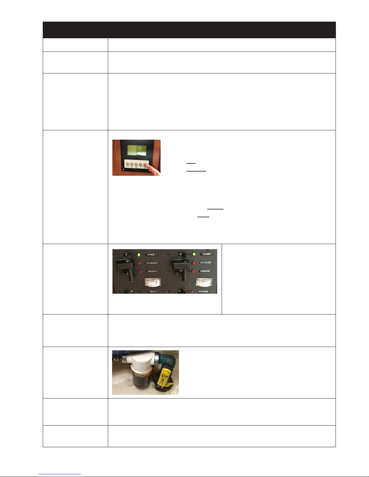
Bilge Pump
Manual Bilge Pump: Located under the cockpit seat (port aft of the helm).
Automatic Bilge Pump: Switch located in the electrical panel. Pump located under
cabin sole at the bottom of companionway stairs
Refrigerator DC switch on the electrical panel.
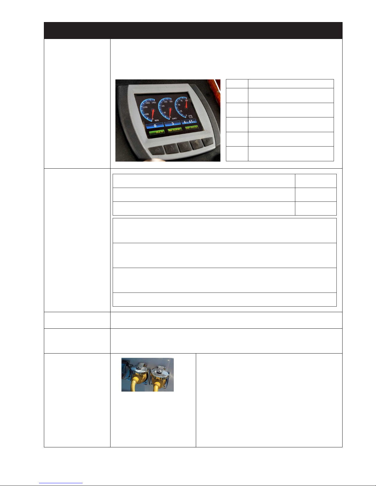
Stove
Propane, tank in the cockpit starboard, aft lazarette. Safety solenoid switch is
below galley sink.
Anchor Locker To access Anchor Locker, release and pull back Spinnaker pole.
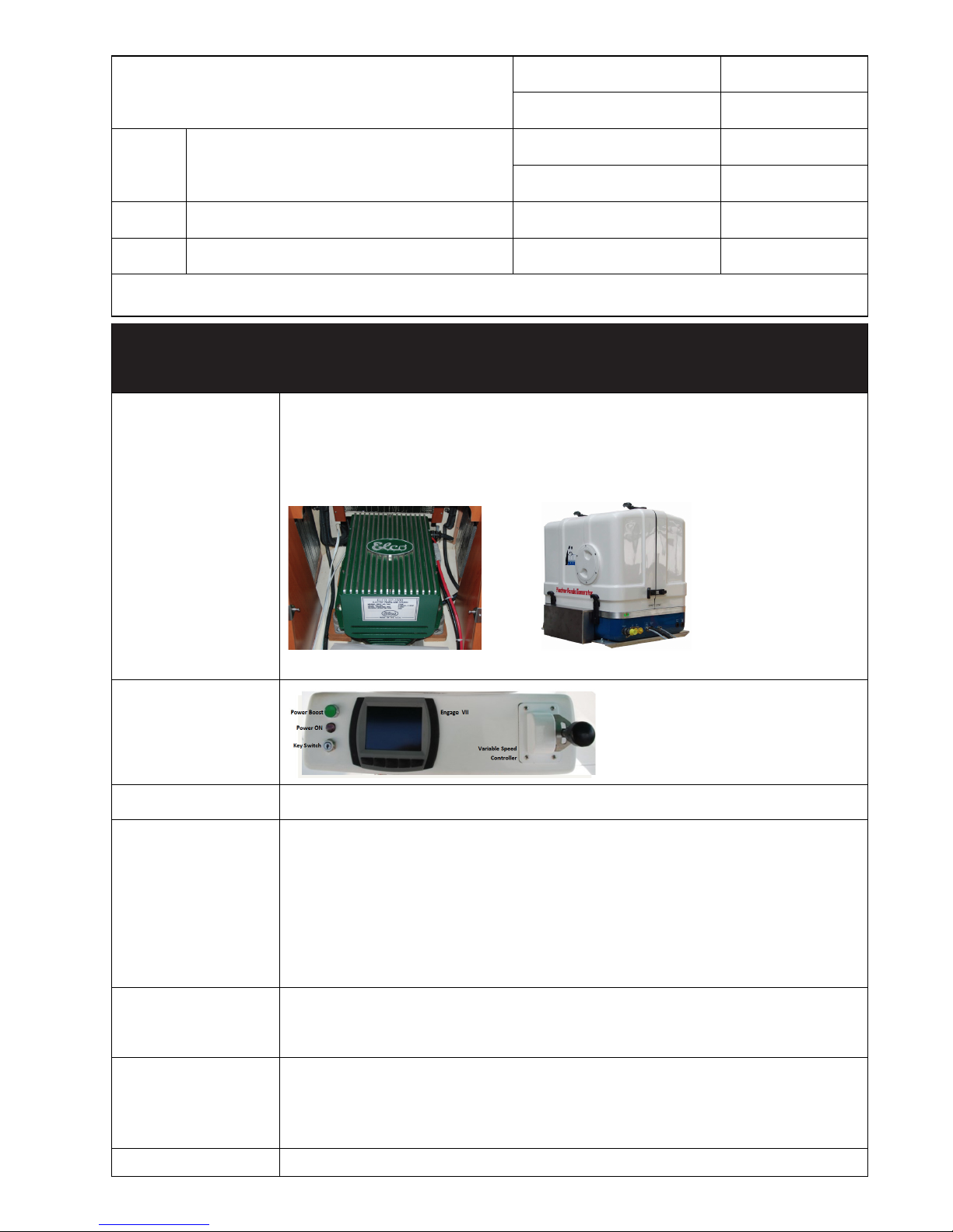
Propeller It has a tri-blade folding propeller with virtually no prop walk. Because it’s a folding
prop it will not charge batteries while sailing
5

Inventory
Item Qty Location
Air Horn 1 Boat Bag
Anchor 1 Bow Anchor Locker
Bell 0
Boat Hook 1 Companionway Top
Bilge Pump Handle 1 Port Lazarette, aft
Canvas
3 Dodger
1 Bimini
4 Winch
1 Helm
Deck Key 1 Boat Bag
Emergency Tiller 1 Port Lazarette, forward
Fenders 4 2 Port side, 2 Starboard Side
Fire Extinguishers
1 Port Lazarette, aft
1Companionway, Top Step
First Aid Kit 1 Head Vanity
Flashlights 1 Boat Bag
Life Jackets 7Port Lazarette
Oil Discharge Placard 1 Galley, Aft Bulkhead
Radar Reector
Signal Flares 4 Boat Bag
Ship Papers 1 Boat Manual
Shore Power Cord 2 Port, Outside Cockpit, Aft
Tool Kit
VHF Radio 1 Navigation Station
Winch Handles 3 Boat Bag
5
This manual suits for next models
2
Table of contents
Other Aventura Boat manuals