Aventura Amicus User manual

06.20.16
Amicus
Boat Manual
DO NOT SAIL IN REVERSE
NO SINGLE HANDED SAILING
MAXIMUM CAPACITY: 10 PASSENGERS
Violation Will Result In Suspension of Members Certication and Charter Privileges
BOAT CODE
A47
SLIP
E129

24707 Dana Drive, Dana Point, CA 92629
949.493.9493 www.AventuraSailing.com
To: Aventura Charter Member
Re: Amicus - Boat Systems Management
It is imperative that you, as the charterer, understand the important information,
guidelines and crucial system operational procedures in the following Boat Manual
prepared specically for Amicus and if not followed correctly will result in signicant
damage to that system which you the charter will be nancially responsible for its repair
should the damage happen during your charter.
Please be sure you understand how these systems work, that they do work prior
to your charter and if you have any questions to be sure to request one of our eet
operations personnel to meet with you at the boat to go over them.
Enjoy your sailing excursion and thank you for chartering from Aventura!
Sincerely,
Chayne Karabasz
Cheyne Karabasz
Fleet Operations Manager
Ofce Phone: 949.493.9493
Cell Phone: 949.310.3160

Table of Contents
Engine
Dipstick 1
Engine Hour Meter 1
Fuel Gauge 1
Engine Control Panel 1
Glow Button 1
Engine Start 1
Throttle/Shift 1
Engine Stop 1
Engine Diagram 2
Electrical & Electronics
Electrical Control Panel 3
Batteries 4
Battery Switches 4
Battery Charging 4
Monitoring Batteries 4
Refrigerator 4
Helm Instruments 4
Inverter/Charger 5
Generator 6
Central Heating &
Air Conditioning System 7
Sails
Jib 8
Main In-Mast Furling System 8
Deck Plate Locations
Water, Waste & Fuel 9
Fuel Tank
Capacity & Filling 9
Seacock and Thru Hull Locations
Opening & Closing Procedures 10
Fresh Water System
Tanks, Valves & Operation 11
Head
Operation & Overboard Discharge 12
Holding Tanks
Emptying Out at Sea 12
LP System
Tank Location &
Operational Procedures 13
Windlass
Breaker Switch Location 14
Operation 14-15
Emergency Tiller
Operation 16
Inventory
Boat Equipment 17
Aventura Chartering
Policy & Procedures P1-P21

Boat Manual Radio Call Sign Amicus
Make 2004 Beneteau
Name Amicus Documentation No. 1158824
Length 46'-09"
Code A47 Beam 14'-02"
Slip E129 Draft 6'-09"
Use this information along with the Discrepancy Report and the Basic Course Syllabus
Engine
Type Yanmar 55 HP engine behind the companionway steps.
Dipstick Located on starboard side of engine, access through panel in starboard aft cabin.
Port Helm
Engine Control Panel
Engine Hour Meter
Fuel Gauge
Glow Button Not required except for very cold engine starts, turn key to right (before starting
engine), wait 10-15 seconds.
Engine Start
1. Turn on engine and house batteries (aft starboard cabin) if not already on.
2. Disconnect shore power.
3. Put transmission in neutral, disengage (black button at base) and throttle 25%
4. Insert Ignition Key and turn to right until engine starts.
5. Before dropping dock lines run through shifting and throttle advance until
comfortable.
Throttle/Shift
Throttle/Shift: Handle on the starboard side of the port helm pedestal. Push forward
for forward, middle for neutral, and back for reverse. Once transmission is engaged,
move throttle as needed for power. To avoid engaging the transmission, push in
black button on the base of the shift lever. Bring the handle to the neutral position to
reset black button and engage the transmission.
Engine Stop Push and hold Red Button on Engine Control Panel.
1

Engine Diagram 2
Ref Description Ref Description
1 Engine Ventilation Cowl 16 Propeller
2 Engine Ventilation Hose 17 Exhaust Hose
3 Anti- Siphon Valve 18 Hatch to the Engine
4 Companionway Stair 19 Battery Switches
5 Fire Extinguisher aperture 20 Intake Strainer
6 House Battery (2 in front of engine, 1 behind) 21 Engine Panel (at port helm station)
7 Engine 22 Skeg
8 Coupling Plate 23 Exhaust Outlet
9Mufer 24 Sea Water Filter
10 Engine Water Intake 25 Fuel Filter
11 Engine Control Handle in the Cockpit 26 Engine Stop Control (on engine panel)
12 Shaft Seal 27 Fuel Shutoff Control
13 Propeller Shaft 28 Fuel – Deck Fill
CLAVETTE 5X70PIGNON
RESERVE 95 L
049746
RESERVE 95 L
049746
RESERVE 95 L
049746
RESERVE 95 L
049746
02
01
01
01
02
02
CLAVETTE 5X70PIGNON
RESERVE 95 L
049746
RESERVE 95 L
049746
RESERVE 95 L
049746
RESERVE 95 L
049746
03
04
05
06
07
09
29
11
12
13
14
15
16
17
19
18
20
21
22
23
24
25
27
28
10
08
30
06
17
23

Electrical Control Panel
12V Lights & Appliance Locations
-3
1 Bicolor Bow Navigation Light 41 Ceiling Light 75 Ceiling Light
10 White Stern Navigation Light 42 Ceiling Light 76 Ceiling Light
4 Tri-color mast head light (on mast) 43 Red Nav Light 77 Reading Light
5 Anchor Light (on mast) 44 Ceiling Light 78 Reading Light
6 Steaming Light (on mast) 45 Ceiling Light 79 Fluorescent Light
7 Deck Light 47 Ceiling Light 80 Reading Light
30 Ceiling Light 48 Ceiling Light 81 Ceiling Light
31 Ceiling Light 49 Ceiling Light 91, 92 Compass Lights
32 Fluorescent Light 61 Reading Light 13 Fresh Water Pump
33 Reading Light 62 Reading Light 14 Bilge Pump
34 Reading Light 70 Ceiling Light 11 Refrigeration
37 Ceiling Light 71 Fluorescent Light 161 Shower Pump – Fwd Toilet
38 Ceiling Light 72 Reading Light 162 Shower Pump – Port Aft Toilet
39 Ceiling Light 73 Reading Light 163 Shower Pump – Stbd Aft Toilet
40 Red Nav Light 74 Ceiling Light Z9 Electric Head
TANK
INDICATOR

Electrical & Electronics
Batteries Batteries located in the engine compartment. Reference engine diagram.
Battery Switches Aft port cabin. Three handles: Vertical is the ON position.
1. Black handle should always be kept in ON (vertical) position.
2. Red house battery #1 handle keep in ON (vertical) position at all times.
3. Red engine start battery #2 handle turn to ON (vertical) position. Turn OFF
(horizontal) while sailing.
4. All batteries should be on to start the engine.
NEVER TURN ANY BLACK OR RED BATTERY SWITCH TO OFF POSITION
WITH THE ENGINE RUNNING.
Battery
Charging
There are 2 methods for charging the batteries on board.
Shore Power:
1. Plug in Shore Power cord at the receptacle on outboard aft combing port side.
2. Make sure it’s plugged in and the AC breaker switch is “ON” at the Dock Box.
3. On the AC power panel Located on port bulkhead forward of navigation station,
toggle on the top “Master Breaker”.
4. Toggle on the “Battery Charger” breaker, red light next to it should be lit.
NOTE: It is not necessary for battery switches to be “ON” for batteries to charge by
this method. At the End of Charter, Leave “House Batteries” On.
Charging Batteries with Engine or Generator
1. Turn both battery switches to “ON” (vertical) position.
2. Start the engine or generator and run until it has “warmed up”.
3. If using engine, move Throttle/Shift (not engaged) lever until the tachometer is
between 1500 and 1800 rpm
4. After batteries are charged and engine or generator is off, turn “Engine Start”
switch OFF.
NOTE: Both batteries require 2 to 4 hours to recharge when charge levels are
low. Monitor battery levels frequently! (SEE: “Monitoring Batteries”)
Monitoring
Batteries
NOTE: It is NOT necessary for battery switches to be ON to monitor batteries.
Locate on Electric Control Panel digital battery monitor, press to check volts.
Monitor Battery Levels Frequently When Using 12 Volt Services!
Never Turn Any Battery Switch Off While Engine is Running!
At the End of Charter, Leave “House Batteries On.
Refrigerator
To activate the refrigerator:
1. Turn on the House Battery switch
2. On the Electric Control Panel toggle on the “Refrigerator” breaker.
3. MONITOR BATTERY LEVELS OFTEN WHEN USING THIS UNIT!
Helm
Instruments
To activate the helm instruments:
1. Turn on the House Battery switch (See: “Battery Switches”)
2. On the Electric Control Panel turn on the “Navigation Instruments” switch.
4

5
Inverter/Charger
The Inverter/Charger Provides
• 120 Volt AC Power From Auxiliary DC
Batteries
• Automatic Battery Charging
• Automatic AC Transfer Switching Between
An External AC Source and Inverter Mode AC
Output.
The Remote Panel Indicators Show
• The battery state-of-charge.
• Power Sharing
• Charger ON/OFF
• Inverter ON/OFF
When plugged into shore–power, the “AC In” the
“Charge (Chg)” light and one of the four battery
status lights will be illuminated in the status bar.
To Use the Inverter with Boat Engine Off
(not connected to shore power.)
1. Turn on the house battery and inverter
switches located in the aft port cabin.
2. Never Run the Water Heater from the
Inverter. This will drain batteries fast! Water
heater switch on AC panel should be OFF
and only when connected to shore power or
generator.
3. Press the “Invert” button under the control
section of the panel. The green light on the
switch will then illuminate.
4. All of the 110v outlets are now live.
5. Reverse steps 2 & 3 to switch off the inverter,
but run the engine for ten minutes after the
inverter is switched off, and check the battery
levels 15 minutes after the engine is turned
off.
6. Monitor the Batteries! Do not use more
than 25% before recharging. Watch "Battery
Status" indicator.
To Use the Inverter with Boat Engine On
1. Turn on the house battery and inverter
switches located in the aft port cabin.
2. Make sure that the water heater switch on the
AC master panel is "OFF".
3. Start the boat's engine; disengage
transmission, bring the RPM up to 1400.
4. Press the “Invert” button under the control
section of the panel. The green light on the
switch will then illuminate.
5. All of the 110v outlets are now live.
Remote Control Panel
Located in Navigation Station
NOTE: Always Ensure That You Have
Switched the Inverter Off When Not Using!
Check that the switch on the panel is no longer
illuminated. Leaving the inverter on will cause your
batteries to rapidly lose their charge.
Inverter Located
Under Navigation
Station Bench Seat
Inverter Switch Located
in Aft Port Cabin.
House Battery and Inverter Switches
Located in Aft Port Cabin.

6
Generator
Amicus is tted with its own generator (located
in starboard stern lazarette) which will run the
110v outlets, the air conditioning and will also
charge the batteries in place of the engine.
To Start the Generator
1. Make sure the 110v systems are off prior to
starting the generator.
2. From AC POWER CENTER located on the
bulkhead forward of navigation station, turn
off the top main breaker switch then slide
cover up and turn "SHIP" switches ON.
3. On ENTEC WEST Generator Control push
toggle switch up to "START" and wait 10
seconds.
4. After 10 seconds of generator running
release toggle and it will automatically move
to the middle "RUN" position.
5. If the generator does not start, wait for one
minute and try again for a maximum of 5
to 7 seconds. If this fails call the Aventura
Emergency number on Discrepancy Report.
6. 3 green indicator lights on panel light up,
If any one does not light up, shut down
the generator. Make a note on the back of
the Discrepancy Report and an Aventura
operations personnel will check systems after
your charter.
Stopping the Generator
1. Turn off all 110v systems
2. Push toggle switch down to the "OFF"
position and the generator will shut down.
3. From AC POWER CENTER turn off "SHIP"
switches then slide cover down then turn
main (shore power) breaker switch back ON.
AC Power Center &
Generator Control Switches
Located on bulkhead forward of Navigation Table.
Generator
START - RUN - STOP
Toggle Switch

7
Central Heating & Air Conditioning System
The Heating & Air Conditioning System works with
either shore power or when generator is running.
Do not operate using inverter.
To Start System Using Shore Power
1. Plug in Shore Power.
2. Make sure the AC switch located under
navigation table marked "SHORE 2" is ON.
3. Turn on "AIR COND 1" switch (located under
navigation table) rst for system to turn on.
Remote Panel located in main cabin above
dinette seat, operating instructions inside of
covers.
4. Turn on "AIR COND 2" switch to activate
system fan for aft cabins operated by Remote
Panel in port aft cabin, operating instructions
inside of covers.
5. At a Remote Panel choose "Heat" or "Cool" and
set desired room temperature and fan speed.
To Start System Using Generator
1. Follow directions "To Start Generator" in its
operations section.
2. After starting generator let it run for 5 minutes.
3. From AC POWER CENTER located under the
navigation table, turn off the top "SHORE 2"
breaker switch then slide cover up and turn
"TRANSFER" switches ON.
4. Turn on "AIR COND 1" switch (located under
navigation table) rst for system to turn on.
Remote Panel located in main cabin above
dinette seat, operating instructions inside of
covers.
5. Turn on "AIR COND 2" switch to activate
system fan in aft cabins operated by Remote
Panel in port aft cabin, operating instructions
inside of covers.
6. At a Remote Panel choose "Heat" or "Cool" and
set desired room temperature and fan speed.
Important Air Conditioning Use Notes:
• Ensure the companionway and all hatches are
closed otherwise the compressors will freeze up.
• The units will work best if the minimum
temperature is set no lower than 70 degrees.
• Set it below this and you risk frosting up the unit
and causing it to shut down. Only select the
"COOL" mode.
• Switch the Remote Panel units ON and OFF
using the ‘ON’ button. The unit will automatically
display the ambient temperature.
To Shut Down System from shore power or
generator, reverse starting procedures.
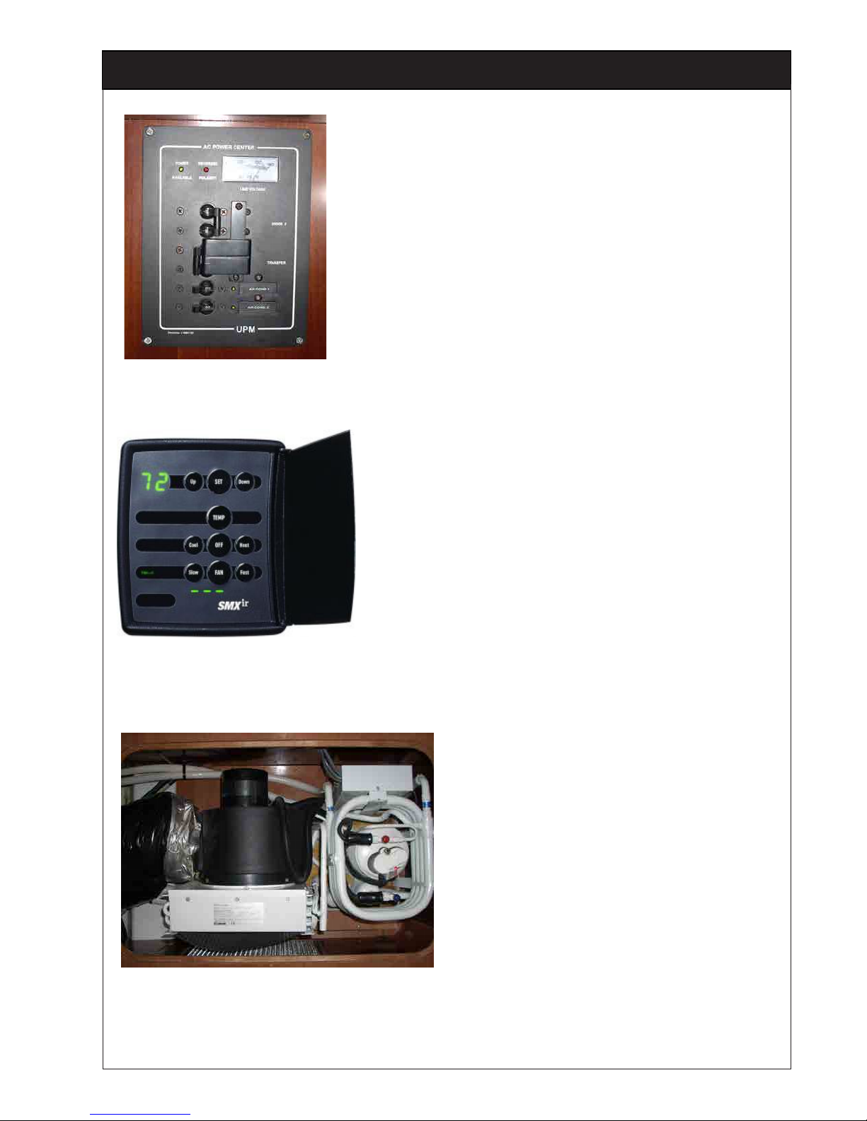
Main Switches
Located Under Navigation Table
Compressor & Main Fan
Located Under Dinette Settee Forward of Galley Sink
Remote Panel
Located in Main Cabin (Saloon) above Dinette
settee and Aft, Port Cabin on side of locker.
Operating instructions inside of cover.

Sails
Jib The jib is a 140% Genoa on a roller furling rig.
Main In-Mast
Furling System
All Lines: Halyards, main sheet, roller furling take up, reef etc. lead aft towards
cockpit on both sides of the companionway.
Important: Keep boat straight into the wind, use two lines to control the furling, the
outhaul and furling lines on port side of the companionway.
IMPORTANT: Do not release the jib or mainsail halyards!
Unfurling Sail:
1. Wrap the Out Haul Line on the electric winch (4 wraps clockwise, securing with
self-tailer).
2. Open the furling clutch.
3. While holding some tension on the furling line, pull out the out-haul line using the
electric winch. Be sure to keep an eye on the sail as it is unfurling to be sure all’s
going smoothly.
Furling Sail:
1. Wrap the Furling Line on the winch (4 wraps clockwise, securing with self-
tailer).
2. Make sure the leech of the sail is kept fairly taught, to accomplish this:
a. Sheet in the mainsheet all the way.
b. Open the “outhaul” rope clutch.
c. Hold some tension on the outhaul line, easing it out while winching in the
furling line. This keeps the furled sail compact and prevents loose sail
material from jamming in the mast cavity.
d. Keep boat straight into the wind to avoid hang ups when furling.
e. Keep an eye on the leech when furling to ensure it does not curl or fold while
going into the mast.
f. Furl in sail stopping when forward edge of triangular UV protective corner
meets the mast.
g. Never force the furler! It is recommended that you use the winch manually
with a handle so you can feel if there is any resistance when furling.
h. Use extreme caution if using the winch in electric power mode. Keep an
eye on it’s perfomance and stoping it’s use if it stalls so not to force the sail to
furl and result in a jamb which you will be charged for repairing.
8

Deck Plate Locations 9
Fuel Tank
Fuel Tank
Tank Capacity 56.5 gallons. The tank is located under the port lazarette..
Fuel ller cap is located on the stern, port side, outboard. Tank vent is on starboard
side of the transom. Use winch handle to open and secure closing.
NOTE: Remove ll cap slowly and hold it rmly so as not lose it overboard should
the tether line break. Do Not Leave Fuel Filler Nozzle Unattended When
Fueling!
4
7
EP PMMA 8mm
PANNEAU
T44
042438 CL
042275 OC
PANNEAU
T30
039865 CL
033470 OC
PANNEAU
T10
025897 CL
033469 OC
PANNEAU
T44
042438 CL
042275 OC
PANNEAU
T30
039865 CL
033470 OC
PANNEAU
T10
025897 CL
033469 OC
PANNEAU
T10
025897 CL
033469 OC
5
1
2
3
6
1Fwd water tank deck ll
2 Fwd waste tank pump out deck plate
3Stbd Mid Ship water tank deck ll
4Port Mid Ship water tank deck ll
5 Aft waste tank pump out deck plate
6Aft water tank deck ll
7Fuel deck ll

Seacock & Thru Hull Locations 10
Ref Description
1 Head Discharge
2 Head Intake
3* Washbasin / Shower Discharge
4Waste Tank Discharge
5 Galley Sink Discharge
6 Engine Cooling Water Intake
7 Ice Box Draining
8 Stern Tube Cooling Intake Valve
9 Speed/Log, Depth Sounder Thru Hull
* The washbasin and shower discharge, connect to the
same thru hull through a set of 1/4 turn valves and a
tee. The washbasin discharge will be the one with a
slightly larger diameter hose. 1
3
2
4
8
5
7
6
9
1
3
4
2
Opening and closing of the seacocks
Open
Closed
Opening & Closing of Seacocks

Fresh Water System 11
2
6
5
1
5
6
7
3
5
6
6
5
10
17
13
18
9
8
7
11
12
16
15
12
11
14
4
The fresh water system
supplies the sink in the galley,
the wash basin and shower
in all of the heads, and the
transom shower. This system
is pressurized by an electric
pump. There is a lter between
the water tank manifold and the
pump.
Never run an electric pump
when the tank is empty. It may
burn out the pump.
To prevent any over pressure in
the system during lling, never
force the lling nozzle deep
down the ller pipe and keep an
PUMP STATION
UNDER STBD SETTEE
BOW WATER TANK
MID STBD WATER TANK
MID PORT WATER TANK AFT STBD WATER TANK
FRESH WATER PUMP
AND FILTER
Pump Station Under Starboard Settee
Ref Description Ref Description
1 Bow Water Tank 55.7 gal 10 Water Heater [capacity 11 gal]
2 Mid Port Water Tank 49.9 gal 11 Shower Discharge Pump
3 Mid Starboard Water Tank 49.9 gal 12 Filter for Shower Discharge
4 Aft Starboard Water Tank 56.5 gal 13 Galley Sink
5 Deck Fill – Fresh Water Tank 14 Washbasin/Shower
6 Vent – Fresh Water Tank 15 Wash Basin
7Water Tank Manifold 16 Shower
8 Filter 17 Transom Shower
9 Fresh Water Pump 18 Icebox

Heads
Main Cabin Manual Flush Procedures
1. On the right side of the bowl is the pump handle. On the back of the pump is
a selector valve for “WET” or “DRY” Flush”.
2. With the selector set to “WET” (left) pump handle to ll the bowl.
3. With the selector set to “DRY” (right) pump handle until the bowl is empty.
NOTE: Nothing goes in the bowl that has not been consumed rst except
marine toilet paper!
Flush Direct Overboard
1. Locate Seacock in sink cabinet and turn handle so that the ow goes out to
sea. Handle is labeled "HEAD DISCHARGE"
2. Use head and ush; the same directions apply as in the above “Flushing
Procedures”.
3. Close the thru hull
Forward Cabin Electric Flush Procedures
1. On the left side of the bowl are two switches. The top switch is for rinsing out
the bowl. The bottom switch when pushed on left side lls the bowl with water,
when pushed on the right side drains the bowl.
NOTE: Nothing goes in the bowl that has not been consumed rst except
marine toilet paper!
Flush Direct Overboard
1. Locate Seacock in sink cabinet (to the right of "TANK DISCHARGE seacock)
and turn handle so that the ow goes out to sea. Handle is labeled "HEAD
DISCHARGE"
2. Use head and ush; the same directions apply as in the above “Flushing
Procedures”.
3. Return “Y” valve so the ow goes to “Tank”
On Discrepancy Report note that Zip-Tie has been cut.
Staff will install new tie.
12
Holding Tanks
Holding Tanks
Capacity: 22 Gallons Ea.
One located in each head
behind a wall panel
To Empty Holding Tank While Out at Sea:
1. Open thru hull labeled "Tank Discharge" located in head sink cabinet.
2. Locate macerator switch on electrical control panel and turn on.
3. Start the macerator pump by pressing and holding the black button (located
in head on sink cabinet) until it runs free - no more than 5 seconds.
4. Close thru hull labeled "Tank Discharge" located in head sink cabinet.
5. Turn off macerator switch on electrical control panel.
On Discrepancy Report note that Zip-Tie has been cut.
Staff will install new tie.
Tank Level Indicators
Located on bulkhead forward
of Navigation Table. Turn on
at Electric Control Panel.

LP Gas System 13
1
2
3
12V Solenoid /
Re
g
ulato
r
Pressure Gauge
Valve on Bottle
Ref Description
1 Gas Locker
2 Valve and Regulator
The propane tank locker is located under the
helm seat on the port side. To use:
1. Turn the LPG switch on the 12v panel. This
opens the solenoid on the tank. To light, turn
the knob you want 90 degrees clockwise,
push the knob in and light the burner using
the automatic ignition.
2. Hold the knob in for 10-15 seconds, then
release. Make sure that the ame goes all
the way around. Reduce any wind that may
hinder this.
3. If you cannot get it to light, check the valve on
top of the connected tank is open.
4. When you have nished using the burners
or the stove switch off the solenoid on the
12v panel before you turn off the knob on
the stove. This will burn the gas out of the
lines and you can test whether the solenoid
is working. If the burner remains lit after
switching the solenoid off you must manually
close off the tank in the cockpit.
The 12v solenoid system is USCG approved
device. You do not need to shut any manual
valves unless you wish (or unless the solenoid
stops working, as indicated above).
If you smell gas or nd that the burners have
gone out by accident, (although appliance
models cut off the gas automatically if the ames
go out) turn off the gas valves and ventilate the
boat in order to get rid of any residual gas. Find
the cause of the problem before re-lighting the
appliance.

14
Anchoring with The Electric Windlass
Continued on Next Page
H
A
B
A
1
H
32
H
Safety and Use
Check for swimmers. Keep
clear of moving anchor rope/
chain.
1. Use Remote Control to
operate windlass (stored
in nav station top drawer).
2. After setting the anchor,
we recommend that the
UP switch is operated
briey. This engages the
internal clutch mechanism,
locking the windlass.
Failure to do this could
result in the rope/chain
creeping out.
3. Do not overload windlass.
4. Avoid stalling windlass.
5. Splice should not be in windlass with anchor raised.
6. Secure anchor to bow tting to prevent accidental release.
7. When riding at anchor, secure anchor rope/chain to a suitable
independent strong point.
WARNING: When not in use, you must isolate windlass with
circuit breaker/isolator.
Manual Free Fall
Note: The clutch operating nut
has a left hand thread, this
means turning it clockwise
loosens it.
1. With operating handle (B)
over clutch nut, engage
gypsy pawl (A) into gypsy
ratchet pocket. Pull
operating handle counter
clockwise to ensure clutch
nut is tight. Release
anchor rope/chain from
independent strong point
and disengage gypsy pawl.
2. Push the operating handle clockwise to release anchor rope/
chain. Control descent of the anchor by pulling gently counter
clockwise on the operating handle.
3. When sufcient rope/chain has been paid out, pull the op-
erating handle rmly counter clockwise. Lock clutch nut by
engaging gypsy pawl and pulling the operating handle counter
clockwise. Disengage gypsy pawl, remove operating handle
and tie off anchor rope/chain.
WARNING!: Care should be taken when releasing anchor and
rope/chain. Loose articles of clothing, watches, bracelets, etc.,
should be clear of moving parts and rope/chain.
Windlass
Breaker Switch
Located in Aft, Port
cabin, low on Base
Panel of Bed. Must be
Switched ON to Operate
Windlass.

15
Anchoring with The Electric Windlass
H
4321
54
2
6
1
H
3
-+
H
Manual Recovery
1. Insert socket screw key into
the clutch operating nut and
turn in a clockwise direction
to release the friction screw.
2. Insert operating handle
into the handle socket
and ratchet the rope/chain
and anchor. Continue until
rope/chain and anchor are
fully recovered. NB: The
gear train will not allow the
End of Charter
Maintenance
1. Wash down the windlass and
anchor using fresh water.
2. Check clutch nut for tightness.
(Remember to hold the gypsy
pawl in position).
3. Check mounting bolts
and nuts for tightness and
condition.
anchor rope/chain to run back.
3. On completion, secure the anchor and anchor rope/chain to an
independent strong point.
4. Insert the socket screw key and turn in an clockwise clockwise
direction to engage the friction screw. Remove the operating
handle from the handle socket.
531
H
H
A
B
A
2 4
Warping
WARNING: Before warping,
secure the anchor rope/chain,
whether it is being used or not,
to an independent strong point.
Disengage Clutch
1. With operating handle (B)
over clutch nut, engage
gypsy pawl (A) into gypsy
ratchet pocket. With gypsy
pawl in position, push
operating handle rmly
clockwise to release clutch
nut.
2. Remove operating handle
from gypsy clutch nut.
Warping
3. Wrap at least 3 coils of rope, loosely, around drum.
4. Start motor.
5. Apply tension to rope gently.
Caution
6. If warping speed is too fast, ease tension in rope.
7. Never wrap chain around Drum.
8. When nished, re-engage clutch.
9. Disengage gypsy pawl when nished.

16
Emergency Tiller Operation
BAT U.S.A
220X280
LONG 530
BAT U.S.A
220X280
LONG 530
LANIAU.P
23/11/99
1
2
6
5
3
4
4
5
To use the emergency tiller, remove the
cover over the rudder stock by using a
winch handle; insert the tiller into the
socket on the rudderstock. You may
remove the steering wheels while using
the tiller, to improve the tiller handle
clearance.
Ref Description
1Emergency Tiller
2 Cap Over Rudder Stock
3 Rudder Stock
4 Steering Cable
5 Quadrant
6 Upper Rudder Shaft Bearing

Inventory
Item Qty Location
Air Horn 1 Boat Bag
Anchor
1 Bow Roller
1Stern Anchor: Aft Port Lazarette
Boat Hook 1 Starboard Aft Cabin Shelf
Bilge Pump Handle 1 Aft Starboard Lazarette
Canvass 3 Dodger Covers
Deck Key 2 Use Winch Handle
Emergency Tiller 1 Starboard Lazarette
Fenders
2 Port
2 Starboard
Fire Extinguishers 2 Galley, Under Counter Cabinet, Port
First Aid Kit 1 Main Cabin's Dinette Bench Seat
Flashlights 1 Boat Bag
Life Jackets 8 Adult Type II - Main Cabin's Dinette Bench Seat
Life Sling 1 Stern Rail
Oil Discharge Placard 1 Galley
Radar Reector
Signal Flares
4 Port Lazarette
4 Boat Bag
Ship Papers 1 In 3-Ring Binder in Navigation Station's Top Drawer
Shore Power Cord 1 Plugs In On Side of Port Aft Cockpit Seat.
Tool Kit 1 Navigation Station's Bench Seat
VHF Radio
1Navigation Station
1Remote Microphone for Port Helm Stored in Navigation Station's
Top Drawer
Winch Handles 2 Boat Bag
17
Table of contents
Other Aventura Boat manuals