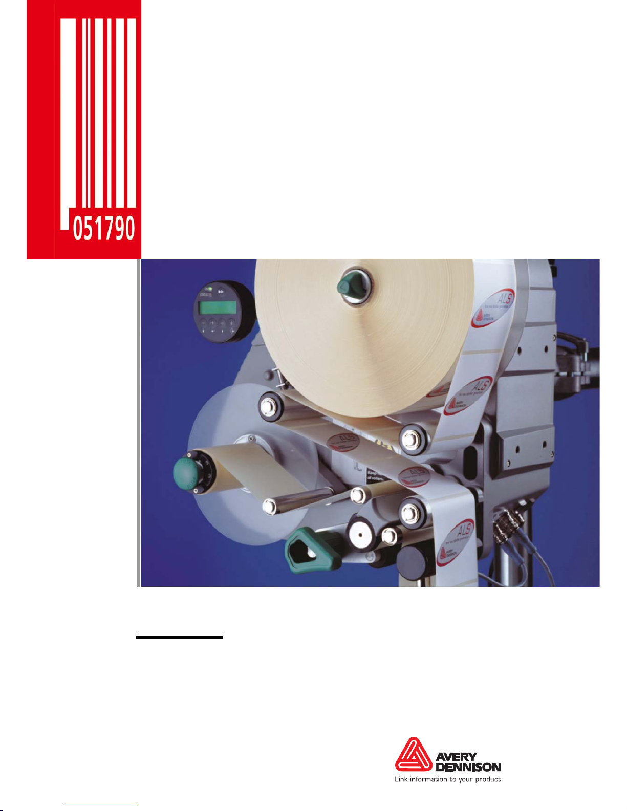
Avery Dennison ALS 104 User manual

ALS
104
USER MANUAL
Label Dispenser
Edition 5 4/2010


3
CONTENTS
ALS
104
GB
1 Please note
1.1 General notes
1.1.1 Validity and binding effect of this manual . . . . 5
Contents . . . . . . . . . . . . . . . . . . . . . . . . . . . . . . .5
Technical status . . . . . . . . . . . . . . . . . . . . . . . . .5
Copyright. . . . . . . . . . . . . . . . . . . . . . . . . . . . . . .5
Manufacturer. . . . . . . . . . . . . . . . . . . . . . . . . . . .5
1.1.2 Illustrations and descriptions. . . . . . . . . . . . . . 6
Signs and symbols . . . . . . . . . . . . . . . . . . . . . . .6
Dangers and risk notes . . . . . . . . . . . . . . . . . . . .6
Figures . . . . . . . . . . . . . . . . . . . . . . . . . . . . . . . .6
Button symbols . . . . . . . . . . . . . . . . . . . . . . . . . .6
Functions. . . . . . . . . . . . . . . . . . . . . . . . . . . . . . .6
Supplementary information . . . . . . . . . . . . . . . . .6
1.2 Safety instructions
1.2.1 Information and qualifications. . . . . . . . . . . . . 7
Follow the instructions. . . . . . . . . . . . . . . . . . . . .7
Keep the product information at hand. . . . . . . . .7
Ensure the required qualifications are met . . . . .7
1.2.2 Operational safety of the unit . . . . . . . . . . . . . 8
Proper usage. . . . . . . . . . . . . . . . . . . . . . . . . . . .8
Protection against injuries by electrical current. .8
Protection against injuries by mechanical action.9
Protection against injuries by chemicals . . . . . . .9
1.2.3 Before beginning production. . . . . . . . . . . . . 10
Due diligence of the operating company and the
service technician . . . . . . . . . . . . . . . . . . . . . . .10
Due diligence of the user. . . . . . . . . . . . . . . . . .10
1.2.4 Safety notes on the unit . . . . . . . . . . . . . . . . 11
2 Product description
2.1 Overview
2.1.1 Components . . . . . . . . . . . . . . . . . . . . . . . . . 12
2.1.2 Control panel. . . . . . . . . . . . . . . . . . . . . . . . . 14
Operating LED. . . . . . . . . . . . . . . . . . . . . . . . . .14
Status LED . . . . . . . . . . . . . . . . . . . . . . . . . . . .14
LCD display. . . . . . . . . . . . . . . . . . . . . . . . . . . .14
Buttons . . . . . . . . . . . . . . . . . . . . . . . . . . . . . . .14
2.1.3 Connection arrangement . . . . . . . . . . . . . . . 15
Connections on the back of the device . . . . . . .15
Sensor connections. . . . . . . . . . . . . . . . . . . . . .15
2.1.4 Mode of operation. . . . . . . . . . . . . . . . . . . . . 16
2.1.5 Technical specifications . . . . . . . . . . . . . . . . 17
Characteristics. . . . . . . . . . . . . . . . . . . . . . . . . .17
Labels . . . . . . . . . . . . . . . . . . . . . . . . . . . . . . . .17
Label sensor . . . . . . . . . . . . . . . . . . . . . . . . . . .17
Power supply. . . . . . . . . . . . . . . . . . . . . . . . . . .17
Electronics. . . . . . . . . . . . . . . . . . . . . . . . . . . . .17
Internal Interfaces . . . . . . . . . . . . . . . . . . . . . . .18
Status messages, test functions . . . . . . . . . . . .18
Dimensions . . . . . . . . . . . . . . . . . . . . . . . . . . . .18
Environmental conditions . . . . . . . . . . . . . . . . .18
Integration . . . . . . . . . . . . . . . . . . . . . . . . . . . . .18
Certificates. . . . . . . . . . . . . . . . . . . . . . . . . . . . .18
2.1.6 Design models . . . . . . . . . . . . . . . . . . . . . . . 19
Right-handed version . . . . . . . . . . . . . . . . . . . .19
Left-handed version. . . . . . . . . . . . . . . . . . . . . .19
2.2 Options
External control panel . . . . . . . . . . . . . . . . . . . .20
Fixed dispensing edge. . . . . . . . . . . . . . . . . . . .20
Swivelling dispensing edge . . . . . . . . . . . . . . . .20
Spring-loaded dispensing edge. . . . . . . . . . . . .20
Pneumatic dispensing edge . . . . . . . . . . . . . . .21
V-shape dispensing edge . . . . . . . . . . . . . . . . .21
Adjustable dispensing edge holder . . . . . . . . . .21
Outer Diameter control sensor . . . . . . . . . . . . .22
Dust/Splash guard. . . . . . . . . . . . . . . . . . . . . . .22
Additional material guide disk . . . . . . . . . . . . . .22
Printer . . . . . . . . . . . . . . . . . . . . . . . . . . . . . . . .23
Narrow label spring kit. . . . . . . . . . . . . . . . . . . .23
2.3 Operating modes
2.3.1 Dispensing mode . . . . . . . . . . . . . . . . . . . . . 24
Dispensing speed . . . . . . . . . . . . . . . . . . . . . . .24
Start offset. . . . . . . . . . . . . . . . . . . . . . . . . . . . .24
Dispensing manually . . . . . . . . . . . . . . . . . . . . .24
2.3.2 Configuration mode . . . . . . . . . . . . . . . . . . . 25
Function of the double-arrow button . . . . . . . . .25
Menus . . . . . . . . . . . . . . . . . . . . . . . . . . . . . . . .25
Functions. . . . . . . . . . . . . . . . . . . . . . . . . . . . . .26
2.3.3 Function overview . . . . . . . . . . . . . . . . . . . . 26
2.3.4 Function descriptions. . . . . . . . . . . . . . . . . . 27
LABEL SETUP menu . . . . . . . . . . . . . . . . . . . .27
MACHINE SETUP menu. . . . . . . . . . . . . . . . . .27
SERVICE FUNCTION menu . . . . . . . . . . . . . . .27
2.4 Inserting label material
2.4.1 Prerequisites . . . . . . . . . . . . . . . . . . . . . . . . 28
2.4.2 Inserting a label roll . . . . . . . . . . . . . . . . . . . 29
Removing spent backing paper. . . . . . . . . . . . .29
Removing glue residue . . . . . . . . . . . . . . . . . . .29
Inserting a new label roll . . . . . . . . . . . . . . . . . .29

4
CONTENTS
ALS
104
GB
2.4.3 Threading the label web . . . . . . . . . . . . . . . . 30
Threading guide . . . . . . . . . . . . . . . . . . . . . . . .30
Threading the label roll at the dispensing edge.31
Threading the label roll onto the drive roller . . .32
Fastening the label roll to the rewinder . . . . . . .32
3 Before operation
3.1 Electrical connections
3.1.1 Power supply standard machine. . . . . . . . . . 33
Checking the power supply setting . . . . . . . . . .33
Connecting the power cable.. . . . . . . . . . . . . . .34
3.1.2 Power supply with dust/splash guard option. 34
3.1.3 Connecting sensors . . . . . . . . . . . . . . . . . . . 34
3.2 Mechanical settings
3.2.1 Adjusting the unwinder’s core diameter . . . . 35
3.2.2 Positioning the pressure roller . . . . . . . . . . . 35
3.2.3 Calibrating the label sensor . . . . . . . . . . . . . 36
3.2.4 Setting the dancer arm restoring force . . . . . 36
4 Operation
4.1 Start-up and shutdown
4.1.1 Turning on the unit . . . . . . . . . . . . . . . . . . . . 37
4.1.2 Starting label dispensing. . . . . . . . . . . . . . . . 37
Dispensing with a product sensor . . . . . . . . . . .37
Dispensing without a product sensor . . . . . . . .37
4.1.3 Stopping the dispensing process . . . . . . . . . 37
4.2 Configuration and monitoring
4.2.1 Function menu settings. . . . . . . . . . . . . . . . . 38
Label length. . . . . . . . . . . . . . . . . . . . . . . . . . . .38
Label stop position . . . . . . . . . . . . . . . . . . . . . .38
Dispensing speed . . . . . . . . . . . . . . . . . . . . . . .39
Label position on the product . . . . . . . . . . . . . .40
4.2.2 Monitoring functions . . . . . . . . . . . . . . . . . . . 41
Missing labels . . . . . . . . . . . . . . . . . . . . . . . . . .41
Recognising the end of the label roll in
advance. . . . . . . . . . . . . . . . . . . . . . . . . . . . . . .41
5 After operation
5.1 Maintenance and cleaning
5.1.1 Changing fuses . . . . . . . . . . . . . . . . . . . . . . 42
5.1.2 Cleaning agents. . . . . . . . . . . . . . . . . . . . . . 43
5.1.3 Regular maintenance. . . . . . . . . . . . . . . . . . 43
Removing paper debris . . . . . . . . . . . . . . . . . . .43
6 Operational failures
6.1 Error messages
6.1.1 Error messaging. . . . . . . . . . . . . . . . . . . . . . 44
6.1.2 List of error messages . . . . . . . . . . . . . . . . . 44
7 Appendix
7.1 EC declaration of conformity

5
1PLEASE NOTE
1.1 GENERAL NOTES
ALS
104
GB
1.1.1 Validity and binding effect of this manual
Contents
Thistechnicalmanualrefersexclusively totheALS104
Label Dispenser. It is written for the purpose of
ensuring professional usageand calibration of the unit.
Prerequisites for the use and adjustment are the
professional installation and configuration of the unit.
For any technical questions you may have that are not
described in this manual, see:
£The service manual of the label dispenser
or
£Request a technician from one of our sales partners.
– Our sales representatives are available to assist
you, particularly with configuring the unit as well as
in the case of malfunctions.
Technical status
Technical status: 10/2008
Software version: 3.21 (front end), 1.84 R01 (drive)
Avery Dennison reserves the right:
– To make modifications to construction parts,
components and software, as well as to employ
comparable components in place of the parts
specified, in keeping with technical advances.
– To modify information in this document.
No commitment will be made to expand these
modifications to include any units delivered earlier.
Copyright
Avery Dennison holds all rights to this manual and its
appendices. Reproduction, reprinting or any other
types of duplication, even of portions of this manual,
may only be carried out with express written consent.
Third persons, in particular competitors, should not be
given access to the information in this manual.
Printed in Germany
Manufacturer
Avery Dennison Deutschland GmbH
Ohmstrasse 3
85386 Eching, Germany
Phone: +49-8165-925-0
Fax: +49-8165-925-231
http://www.machines.averydennison.com
1PLEASE NOTE
1.1 GENERAL NOTES

6
1PLEASE NOTE
1.1 GENERAL NOTES
ALS
104
GB
1.1.2 Illustrations and descriptions
Signs and symbols
Various information types are indicated in different
ways within the document in order to simplify
readability and comprehension.
Sentences starting with an arrow are instructions and
guidelines.
£Perform the instructions one after another in the
specified order.
The following information begins with a dash:
–Lists
– Mode descriptions
– Descriptions of prior steps
– Prerequisites for following actions
Dangers and risk notes
Important directions that you must absolutely observe
are particularly emphasized:
WARNING!
A warning refers to risks that can lead to
serious injury or death! The warning
contains safety measures to protect the
relevant persons.
£Always follow the instructions.
CAUTION!
A caution indicates risks that can lead to
property damage or injuries to persons
(minor injuries). The caution note contains
instructions for preventing damages.
£Always follow the instructions.
Figures
Texts are accompanied by figures where necessary.
Figures are indicated using figure numbers in [square
brackets]. A capital letter after a figure number, for
example [12A], refers to a specific section of the figure.
Generally, the label dispenser shown is an ALS 104
right-handed version. The left-handed version is only
shown where it is necessary to differentiate between
the two.
Button symbols
– The buttons of the control panel are depicted as
symbols.
– The symbols are depicted with a ‘+’ (PLUS SIGN)
between them if more than one button is to be
pressed. +
Functions
Functions are displayed in grey in the text with the
following structure, MENU NAME > Function name.
Supplementary information
The expert symbol indicates actions that are
only to be performed by qualified and specially
trained personnel.
The information symbol indicates notes and
recommendations, as well as additional
information.
Equipment:
– Equipment, for example lubricants or
cleaning agents

7
1PLEASE NOTE
1.2 SAFETY INSTRUCTIONS
ALS
104
GB
1.2.1 Information and qualifications
Follow the instructions
WARNING!
Safe and efficient operation of the label
dispenser can only be guaranteed if you
observe all necessary information.
Product liability and warranty claims can
only be asserted if the unit was operated in
accordance with the directions in the
manual.
£Before operating the unit, read the
operating instructions and all other notes
carefully.
£Observe the additional safety and
warning notes on the label dispenser.
£Only permit competent people to operate
and configure the label dispenser.
Keep the product information at hand
With respect to this manual:
£It should be kept at the location where the
unit is installed and be available to the
operator.
£It should always be legible.
£Iftheunitis sold, the manualshouldbemade
available to the new owner.
£The safety and warning notes affixed to the
unit itself must be kept clean and legible.
Missing or damaged signs must be replaced.
Ensure the required qualifications are met
£Ensure that only trained and authorized personnel
operate, configure and service the unit.
£Only allow qualified and well-trained expert
personnel or service technicians to perform
configurations.
£The responsibilities with regard to operation,
configuration and maintenance should be clearly
defined and consistently maintained.
£In addition, personnel should also be instructed on
aregularbasisin matters ofoccupationalsafetyand
environmental protection.
Qualification for operation
The instruction of personnel using the unit must ensure
that:
– The operating personnel can use the unit on their
own and safely.
– The operating personnel can remedy small
operational disruptions on their own.
£At least two people must be instructed in the unit’s
usage.
£Enough label material must be provided for testing
and instructional purposes.
Qualifications for configuring
The configuration of the controls requires
qualified expertise:
– Personnel configuring the unit must be
acquainted with the functionality of the label
dispenser.
– Personnel configuring the unit must be
acquainted with the modes of operation
withinthe facilityin whichthe labeldispenser
is integrated.
– The personnel configuring the unit must be
able to use the additional menus properly
and appropriately for specific project
requirements.
1.2 SAFETY INSTRUCTIONS

8
1PLEASE NOTE
1.2 SAFETY INSTRUCTIONS
ALS
104
GB
1.2.2 Operational safety of the unit
Proper usage
The ALS104 Label Dispenser is a fully automatic unit
for attaching self-adhesive labels to products or
packaging.Thecompanyoperatingthe unit mustinstall
it with suitable equipment to protect operating
personnel from danger; for example, the danger of the
hands or fingers being crushed by reaching in between
the product and the dispensing edge.
WARNING!
Improper usage of the unit can cause
accidents, property damage and production
downtime!
£Only use the unit in accordance with the
instructions specified in this manual.
£Do not operate the unit without the
required safeguards.
£Only configure the unit in accordance
with this manual and with the required
care.
£Only use original accessories.
£Do not make any modifications or
alterations to the unit.
£Repairs to the device may only be
performed by authorised specialists who
are aware of the risks involved.
Protection against injuries by electrical
current
WARNING!
The machine operates using mains voltage!
Touching live electrical parts may expose
you to hazardous electrical currents and
may lead to burns.
£Only operate the unit once the housing
has been reassembled properly.
£Only connect the unit to a properly fitted
power socket that is grounded.
£Before cleaning, switch off the unit and
remove the power cable from the socket.
£Only link the unit to devices that fulfil the
SELV (safety extra-low voltage) circuit
requirements specified in EN60950.
WARNING
The unit is not protected against splashing
water in its standard model.
£Keep the unit dry.
£If liquids have penetrated the unit, switch
it off and disconnect or unplug the power
cable immediately. Inform a service
technician.
WARNING
The device is only completely disconnected
from the mains if the power cable is
unplugged.
£Make sure the power supply socket is
accessible.
£In case of emergency, switch off the
device and disconnect the power cable.
CAUTION
Atoohighorlowsupplyvoltagecandamage
the unit.
£Only operate the device using the system
voltage indicated on the nameplate.
£Ensure that the mains voltage set on the
unit is the same voltage as that provided
by the electricity supplier.

9
1PLEASE NOTE
1.2 SAFETY INSTRUCTIONS
ALS
104
GB
Protection against injuries by mechanical
action
WARNING!
Risk of injury due to moving and rapidly
rotating parts!
– Long hair, loose jewellery, long sleeves,
and so on arenot permissible when using
the unit.
£Sufficient protective clothing must be
worn.
£Keep moving parts free from
obstructions even when the unit is not
switched on, if there is a chance the
machine might be turned on.
£Switch off the machine before making
any mechanical settings.
£Do not wear ties, loose clothing,
jewellery, wrist watches or similar items
on your person when near the operating
unit.
WARNING!
There is a risk that you may get your fingers
or hands crushed on the dispensing edge by
products on the conveyor belt!
£Never reach between the product and the
dispensing edge while the unit is in
operation or ready for operation.
£Never reach behind the safety guard or
remove it while the unit is in operation.
Protection against injuries by chemicals
CAUTION!
Operatingmaterialssuchascleaningagents
or the solvents in glues can be damaging to
health.
£Always follow the instructions, use and
safety regulations specified by the
manufacturer!

10
1PLEASE NOTE
1.2 SAFETY INSTRUCTIONS
ALS
104
GB
1.2.3 Before beginning production
Due diligence of the operating company
and the service technician
£Ensurethatthefollowingprerequisites arefulfilledin
accordance with the service instructions:
– The machine is installed properly and configured in
accordance with the guidelines.
– All required safety mechanisms havebeen installed.
– The unit has performed at least one successful test
run.
– The unit is connected to the power supply.
£The users have the required personal protective
equipment, for example, a hairnet. Ensure that the
protective equipment is utilised correctly.
Due diligence of the user
£Check that the safety installations are working
properly.
£Inspect the machinery for any visible damage.
Report any ascertained defects immediately.
£Use the required personal protective equipment
correctly, for example, wear a hairnet.
£Remove any unnecessary materials and objects
from the operating area of the unit.
£Ensure that only authorised persons are within the
operating range of the machine.
£Ensure that starting up the machine will not injure
anyone.

11
1PLEASE NOTE
1.2 SAFETY INSTRUCTIONS
ALS
104
GB
1.2.4 Safety notes on the unit
CAUTION!
Warning notes on the unit represent
important information for the personnel
using it.
£Do not remove warning notes.
£Replace any missing or illegible
warnings.
The ‘Pinch Point’ warning [1] note warns you of the
danger posed by the machine’s rotating parts; they can
trap items and draw them in.
The blue label ‘Read manual’ [2] demands that users
read the unit instructions.
[1] Left: ‘Pinch Point’ warning. Right: Position of the warning note on the ALS104. Item number of the label: A5346.
WARNING
!
Pinch point.
Keep hands clear
of rollers.
A5346
[2] Left: ‘Read manual’ notice. Right: Position of the notice on the ALS104. Item number of the label: A5331.
Handbuch lesen!
Read the manual!
Lisez le manuel!
Lea el manual!
Legga il manuale!

12
2PRODUCT DESCRIPTION
2.1 OVERVIEW
ALS
104
GB
2.1.1 Components
[3] ALS 104 Label Dispenser (right-handed version)
A
B
D
E
G
H
J
K
L
N
M
O
I
F
C
2PRODUCT DESCRIPTION
2.1 OVERVIEW

13
2PRODUCT DESCRIPTION
2.1 OVERVIEW
ALS
104
GB
A Control panel
– For sending commands to the device and for
displaying operating states and error messages.
– An optional external control panel can also be
connected to the device.
B Dispenser
– Dispenser mandrel grasps the label roll.
C Core diameter adapter
– For adjusting the diameter of the dispenser mandrel
to match the core diameter of the label roll.
D Adjusting knob
– Turning this in a clockwise direction secures the
label roll on the dispenser.
E Deflection rollers
F Dispensing edge bracket
G Label sensor
– Stops the label feed after a label has been
dispensed
H Pressure roller
– Prints the label once it is stuck to the product
I Dispensing edge
– Standard: (non-adjustable) L-shaped dispensing
edge
– The following options are available: V-shaped
dispensing edge, adjustable L-shaped dispensing
edge, spring-loaded L-shaped dispensing edge,
pneumatic L-shaped dispensing edge
J Drive roller
– Drives the label material forwards
K Pressure mechanism
– Presses the pressure roller against the drive roller
– Prevents the backing paper from slipping through
– Releases automatically once the backing paper has
been drawn around the drive roller
L Tensioning plate
– Keeps the backing paper taut
M Rewinder
– Rolls up the used backing paper
N Release button
– Pressing this button reduces the diameter of the
rewinder core.
– Allows the easy removal of the rewound backing
paper
O Dancer arm
– Keeps the backing paper stretched tight evenly
– Arrests the rotation of the material roll if tension
diminishes

14
2PRODUCT DESCRIPTION
2.1 OVERVIEW
ALS
104
GB
2.1.2 Control panel
Operating LED
Lights up green when the device is switched on.
Status LED
[5] Meaning of the red status LED
LCD display
– Displays functions, configured values, operating
states and error messages
– What is displayed at any one time depends on the
operating status of the device; these screens are
explained in the section “Operating modes” on
page 24.
Buttons
The button assignments depend on the currently active
operating mode and are described in the section “Ope-
rating modes” on page 24.
LED Explanation
On Dispensing
mode
Off Configuration
mode
Flashing Error [4] Control panel of the ALS104
AOperating LED
BStatus LED
CLCD display
DButtons
Speed
12.2 fix
Offset
0.0
++
–
–
ON
STATUS
A
B
C
D

15
2PRODUCT DESCRIPTION
2.1 OVERVIEW
ALS
104
GB
2.1.3 Connection arrangement
Connections on the back of the device
[6] Connections on the back of the ALS104:
APower supply connection
BSignal interface (Sub-D15 port)
CRS232 interface (Sub-D9 port)
DConnection for external control panel (PS/2 port)
Sensor connections
[7] Position of the sensor connections on the ALS104
[8] Arrangement of the sensor connections (schematic) on the LH (left figure) and RH (right figure) devices.
AProduct sensor
BLabel sensor
COptional: Signal outputs
DSpeed sensor (required for automatic speed adaption)
ERoll diameter sensor
A
B
CD
LH RH
AA
B B
CC
D D EE

16
2PRODUCT DESCRIPTION
2.1 OVERVIEW
ALS
104
GB
2.1.4 Mode of operation
In labelling mode, the strip is first pulled from the label
roll around the dancer arm [9A], which consistently
maintains even tension in the label strip. The feed roller
[9D] behind the dispensing edge [9C] draws the strip
across the dispensing plate. The label is unfixed from
the backing paper on the dispensing plate and is
pressed onto the product with the pressure roller [9B].
The feed roller drives the label strip forwards the length
of one label and stops until the next product arrives at
the dispensing plate The feed is started by the product
sensor mounted on the conveyor belt. The stop control
provided by the label sensor on the dispensing edge
ensures the feed is halted as soon as a gap is detected
between two labels.
The spent backing paper runs from the dispensing
edge around the drive roller [9D], and then overthe ten-
sioning plate to be rewound [9E]. The tensioning plate
ensures that rewinding is performed evenly.
The entire operationof the label dispenser is controlled
and monitored electronically. If errors occur, the device
controls output an appropriate notification for the ope-
rator. If necessary, the labelling operating mode is hal-
ted automatically. An electronic signal is output at the
same time. The signal can be fed to an external cont-
roller and evaluated. [9] The ALS104 is ready for operation in its idle mode.
ADancer arm
BPressure roller
CDispensing edge
DDrive roller
ERewinder
D
A
C
E
B

17
2PRODUCT DESCRIPTION
2.1 OVERVIEW
ALS
104
GB
2.1.5 Technical specifications
Characteristics
1) At a speed range of 5 to 30m/min
Labels
2) Depending on the dispensing edge width.
Label sensor
Power supply
Electronics
Dispensing speed: up to 30m/min
Labelling halt precision 1)
at the peeling edge: ± 0.5mm
Speed control: constant speed or auto-
matic speed adaption
using speed sensors
Label material: Converted self-adhesive
label material with liner
Internal rewinding yes
Material width
(including backing pa-
per):
10 to 110mm 2)
Label width: bis 110mm2)
Label length: 5 to 600mm
Label roll
Winding direction:
Unwinder (outer) Ø:
Rewinder (outer) Ø:
Core (inner) Ø:
face in or face out
up to 300mm
up to 200mm
38.1/76.2/101.6mm
(1.5/3/4”)
Distance to peel edge
L-shape dispensing
edge:
V-shape dispensing
edge (fix):
V-shape dispensing
edge (variable):
19mm
77mm
79-207mm
Transmission sensor: Wenglor OPT242-P800
optical, NPN
System voltage: 115V (AC) at 60Hz po-
wer frequency
230V (AC) at 50Hz po-
wer frequency
Power consumption: 300VA
Current consumption: 2A at 115V system
voltage
1A at 230V system
voltage
Processor: 16Bit DSP
RAM: 4kB
ROM: 64kB
Slot for plug-in-cards: none
Realtime-clock: none
Control panel: graphical display with
128x32pixels, 2 lines,
5 buttons
Control panel interface: RS422 (Mini DIN 6 con-
nection) for remote cont-
rol
maximum cable length:
10m
Service interface: RS232C, D-Sub 9
Sensor interfaces for
external sensors
Label sensor:
Product sensor:
APSF-Sensor (Rotary
encoder):
Outer diameter
checking sensor:
(opto-isolated; D-Sub 9
connector, each on a se-
parate 4-pin M12 connec-
tor)
Wenglor OPT242-P800
(adjustable by potentio-
meter) or alternate sen-
sors or signals,
PNP/NPN3), 24V
PNP/NPN3), 24V
single-phase, PNP/
NPN3)/ P-P, 24V,
max. 20kHz
PNP/NPN, 24V

18
2PRODUCT DESCRIPTION
2.1 OVERVIEW
ALS
104
GB
3) Selectable by jumper setting
Internal Interfaces
Status messages, test functions
Dimensions
4) Measurements without the dispensing plate bracket and dispensing plate
Environmental conditions
Integration
Certificates
– CE, TÜV/GS, FCC, CCC, GOST, NRTL, US/CA
– The regulation DIN EN 55022 requires for class A
devices the following text to be printed in the
manual:
„WARNING: This is a class A product. In a domestic
environment this product may cause radio
interference in which case the user may be required
to take adequate measures.“
– The FCC regulation requires the following
information text for class A products:
„NOTE: This equipment has been tested and found
to comply with the limits for a Class A digital device,
pursuant to Part 15 of the FCC Rules. These limits
are designed to provide reasonable protection
against harmful interference when the equipment is
operated in a commercial environment. This
equipment generates, uses and can radiate radio
frequency energy and, if not installed and used in
accordance with the instruction manual, may cause
harmful interference to radio communications.
Operation of this equipment in a residential area is
likely to cause harmful interference in which case
the user will be required to correct the interference
at his own expense“
PLC outputs:
(connection with D-Sub
15 connector, optional
with 8-pin M12)
3x PNP, 24V, max.
500mA/channel, total
permissible output cur-
rent: 1500mA
One insulated relay out-
put, max. 125mA (NC/
NO), functions parallel to
the PNP outputs (selec-
table)
Optional output via an
8-pin M12 connector
UART for RFID none
Connector for add motor
driver boards none
Thermal print head
connectors none
Automatic halt, if ... the label roll is spent or
no gap was found.
… the maximum allowab-
le number of missing la-
bels has been exceeded.
Test functions: Automatic diagnostics
check when switched on
Height x width x depth: 4) 492 x 488 x 353 mm
Weight: 33kg
Operating temperature: 5 to 40°C
Humidity: 30 to 85%, (non-conden-
sing)
Noise level (at a distance
of 1m): 70dB(A)
Protection class: IP 21
IP 65 optional (with ex-
tras)
Mounting points: side / bottom / rear
Labelling positions: top / side / bottom
Dispensing edges: V-shape
L-shape; fixture 90° pivo-
ting, for all L-shape types
(4“ L-shape disp. edge:
material width up to
100mm only)

19
2PRODUCT DESCRIPTION
2.1 OVERVIEW
ALS
104
GB
2.1.6 Design models
The ALS 104 Label Dispenser is available in two de-
signs for differing conveyor belt directions.
Right-handed version
– The products are transported from left to right [10].
– The dispensing edge is located on the right side.
– Abbreviation: RH
Left-handed version
– The products are transported from right to left [11].
– The dispensing edge is located on the left side.
– Abbreviation: LH
The label dispenser operation described in this
manual is based on the right-handed version.
The left-handed version is only taken into ac-
count if the explanations or figures of the de-
signs differ significantly. [10] Right-handed version
AALS104
BProduct on the conveyor belt
CLabelled product
[11] Left-handed version
A
B C

20
2PRODUCT DESCRIPTION
2.2 OPTIONS
ALS
104
GB
External control panel
– An external control panel can be connected in
addition to the integrated control panel.
– An external control panel is useful if the standard
control panel is inaccessible due to the position in
which the unit is installed.
Fixed dispensing edge
– The dispensing edge has a fixed connection to the
brackets.
– To adjust the vertical position, lift/lower the entire
device.
– The slope angle can be adjusted by rotating the
brackets (see the service manual for further details).
Swivelling dispensing edge
– Thepositionofthe dispensingedge canbeadjusted
vertically.
– The device need notbe movedto adjustthe position
of the dispensing edge; the device’s mounting need
not be dismantled.
Spring-loaded dispensing edge
– The dispensing edge is pivoted. A torsion spring in
the dispensing head presses the dispensing edge
downwards and onto the surface of the product.
– Allows compensation for height differences
between the products or on the product surface.
[12] External control panel
[13] Standard dispensing edge
[14] Swivelling dispensing edge
[15] Spring-loaded dispensing edge
2.2 OPTIONS
Other manuals for ALS 104
1
Table of contents
Other Avery Dennison Printer Accessories manuals

Avery Dennison
Avery Dennison ALS 306 User manual

Avery Dennison
Avery Dennison SONIC Knife Operating manual

Avery Dennison
Avery Dennison Monarch AAFES kit User manual

Avery Dennison
Avery Dennison Monarch 9433 User manual

Avery Dennison
Avery Dennison Mobile Work Station (MWS) Monarch 9876 Installation and operation manual

Avery Dennison
Avery Dennison Power Stacker User manual

Avery Dennison
Avery Dennison Cutter 2000 User manual

Avery Dennison
Avery Dennison JUNIOR REWINDER Guide

Avery Dennison
Avery Dennison ALX 720 User manual

Avery Dennison
Avery Dennison Cutter 2000 Guide