Avery Dennison Cutter 2000 User manual

03/10 Rev. 5.04-01 TECHNICAL MANUAL
Cutter 2000
Connection, Setup, Service
Safety Notes ................................................. 2
General Notes ............................................... 3
Proper Usage ............................................ 3
Technical Specifications ............................ 3
System requirements .................................... 4
Preparation for peripheral devices ............ 4
Connecting the cutter .................................... 5
Activating the cutter ...................................... 7
Activating the TTX 350 / TTK ....................7
Activating the 64-xx / AP 5.4 / AP 5.6 /
AP7.t ......................................................... 7
Error message after activating the printer . 7
Parameter settings .................................... 8
Status reports ............................................9
Triggering a cut ..........................................9
Servicing the cutter ......................................10
General notes ..........................................10
Cutter motor .............................................10
Toothed belt .............................................11
Photoelectric switch .................................11
Oscillator Disc, Toothed Wheel ...............12
Circular cutter ..........................................13
Bottom cutter ...........................................15
Accessories .................................................16
Stripper plate ...........................................16
Appendix .....................................................17
Cable harness ..........................................17

03/10 Rev. 5.04-01 TECHNICAL MANUAL Connection, Setup, Service
Cutter 2000
2
Safety Notes
WARNING!
Danger of getting your fingers cut by the cutter blades!
«Cleaning of the cutter must be done very carefully.
«Don´t touch the cutter during printing/cutting operation.
«Don´t use the cutter as a handle to carry the printer.
«Switch off the printer and pull out the mains connector before any operation
that requires touching the cutter (e.g. mounting, cleaning, inserting label
material, …).
«Don´t use sharp edged objects to clean the cutter blades.

03/10 Rev. 5.04-01 TECHNICAL MANUAL Connection, Setup, Service
Cutter 2000
3
General Notes
Proper Usage
The cutter option (subsequently referred to as the "cutter") is a peripheral de-
vice for label printers of the type TTK, TTX 350, 64-xx, AP 5.4, AP5.6 or
AP7.t. The cutter is designed for cutting label material after it has been prin-
ted.
Technical Specifications
Properties The cutter blade cuts self-adhesive, cardboard and synthetic materials up to
240g/m2anduptoamaterialthickness of 0.9 mm–consideringthefollowing
exceptions:
Cut width Cutters of varying widthsare intended for use with printers ofthe 64-xx series
to allow labels to be cut up to the maximum material width of the printer being
used.
Double cut With the double cut function, the operator can remove gaps from the label
material where required. Here the cut gap can be set from 1 to 5 mm.
CAUTION! - Keep to the following rules in order not todamage or to soil the
cutter blade.
«The 8" wide cutter must not be used for materials exceeding 160 g/m2.
«Fiber strengthened materials (e.g. Tyvek) must not be cut.
«If using self-adhesive material, cut between the labels (backing paper).
Otherwise, the adhesive will stick to the cutter blades and will have a
negative effect on the cutting function.

03/10 Rev. 5.04-01 TECHNICAL MANUAL Connection, Setup, Service
Cutter 2000
4
System requirements
Cutters in the appropriate width can be operated with the following printers:
System Requirements
Preparation for peripheral devices
For using the printers with a cutter, they must be especially equipped
(Tab. 2). This so called peripherals preparation consists mainly of an additio-
nal output stage board for the motor of the peripheral device and of some ad-
ditional connection cables.
Peripheral test TTK/TTX 350:
«Set parameter SYSP > PEPH to KNIF.
If the printer displays the status message ST68 after the ENTER key is pres-
sed, the peripheral board is not installed. If ST68 does not appear or if a dif-
ferent status message is displayed, then the printer has been set up for
peripheral devices.
64-xx / AP 5.4 / AP5.6 / AP7.t:
«Make a service status printout: Call parameter PRINT INFO > Service Status.
64-xxandAPx.x printers are equipped withperipheralpreparationifthetopic
“Peripheraldriver” can be found below the header “Peripheraldriver” on the
printout.
Printer Cutter width
64-04 / TTK / TTX 350 / AP 5.4 / AP7.t 4"
64-05 5"
64-06 6"
64-08 8"
[Tab. 1] The cutter width must match the printwidth of the printer.
Printer Peripherals preparation
64-xx optional
TTX 350 optional
TTK standard
AP 5.4/5.6 standard with printer version „Peripheral“
AP7.t standard
[Tab. 2] Only the TTK is in any cases equipped with the peripheral preparation. For the
other printer types this is an option.

03/10 Rev. 5.04-01 TECHNICAL MANUAL Connection, Setup, Service
Cutter 2000
5
Connecting the cutter
The cutter (fig. 1) is secured to the printer
by two screws and an adjustment plate. By
moving the adjustment plate, the cutting
line can be set parallel to the print image.
Tools
•Allan key 3mm
•Socket wrench, size 8
Assembly / Disassembling
1. Remove the tear-off edge (3) by
unscrewing the thumb screw (4).
2. Remove the cutter cover (1) by
unscrewing the two fastening screws (2,
fig. 2).
3. Screw on the cutter in place of the cutter
cover. To do this use the fastening screws
of the cutter cover (2) (2x Allan key screws
M 5x20). Initially just screw them in
slightly.
PContinued overleaf.
WARNING!
Danger of injury if the cutter is
activated unintentionally!
«Before beginning service work,
switch off the printer and pull out
the mains power supply plug.
1
3
2

03/10 Rev. 5.04-01 TECHNICAL MANUAL Connection, Setup, Service
Cutter 2000
6
4. Attach the adjustment plate (5) by
unscrewing the top left hexagonal screw
(6) on the print or draw unit, place the
adjustment plate underneath, and then
tighten the screw again - initially only
lightly (fig. 4).
¯The square axle of the cutter unit must
rest in the square recess of the adjustment
plate.(fig. 4)
¯AP 5.4/5.6 only:
The adjustment plate differs from the
64-xx/TTX 350/TTX version. It is provided
with every AP 5.4/5.6 printer (fixed on the
printer bottom with adhesive tape).
5. If necessary, position the adjustment
plate (4) with the help of the hex screw (6)
so that the cut image and print image are
lying parallel (fig. 5).
6. Tighten all three fastening screws.
7. Plug the knife motor cable into the socket
on the front of the printer (fig. 6).
Function check for AP 5.4 / AP5.6 /
AP7.t
For testing purposes can be triggered a cut
by calling parameter SERVICE FUNCTION >
Cutter Test. This way, the cutter function can
be tested without changing the printer peri-
pheral setting.
CAUTION! - Under no circumstances
should the plug be attached or re-
moved when the device is switched
on, as otherwise the device electron-
ics could be damaged.
4
5
6

03/10 Rev. 5.04-01 TECHNICAL MANUAL Connection, Setup, Service
Cutter 2000
7
Activating the cutter
After installation, the cutter must still be activated by setting the correspon-
ding parameters in the parameter menu.
Activating the TTX 350 / TTK
«Call parameter SYSP > PEPH and set it to KNIF.
The printer will now be reset. The cutter is rotated automatically to its correct
starting position.
Activating the 64-xx / AP 5.4 / AP 5.6 / AP7.t
«Call parameter SYSTEM PARAMETERS > Peripheral device and set it to „Cutter“.
The printer will now be reset. The cutter is rotated automatically to its correct
starting position.
Error message after activating the printer
If the starting position of the cutter blade can not be found, the following sta-
tus message appears (depending on the printer type):
64-xx/AP5.4/
AP5.6/AP7.t
TTX350/TTK
«Press the Online button to acknowledge the message.
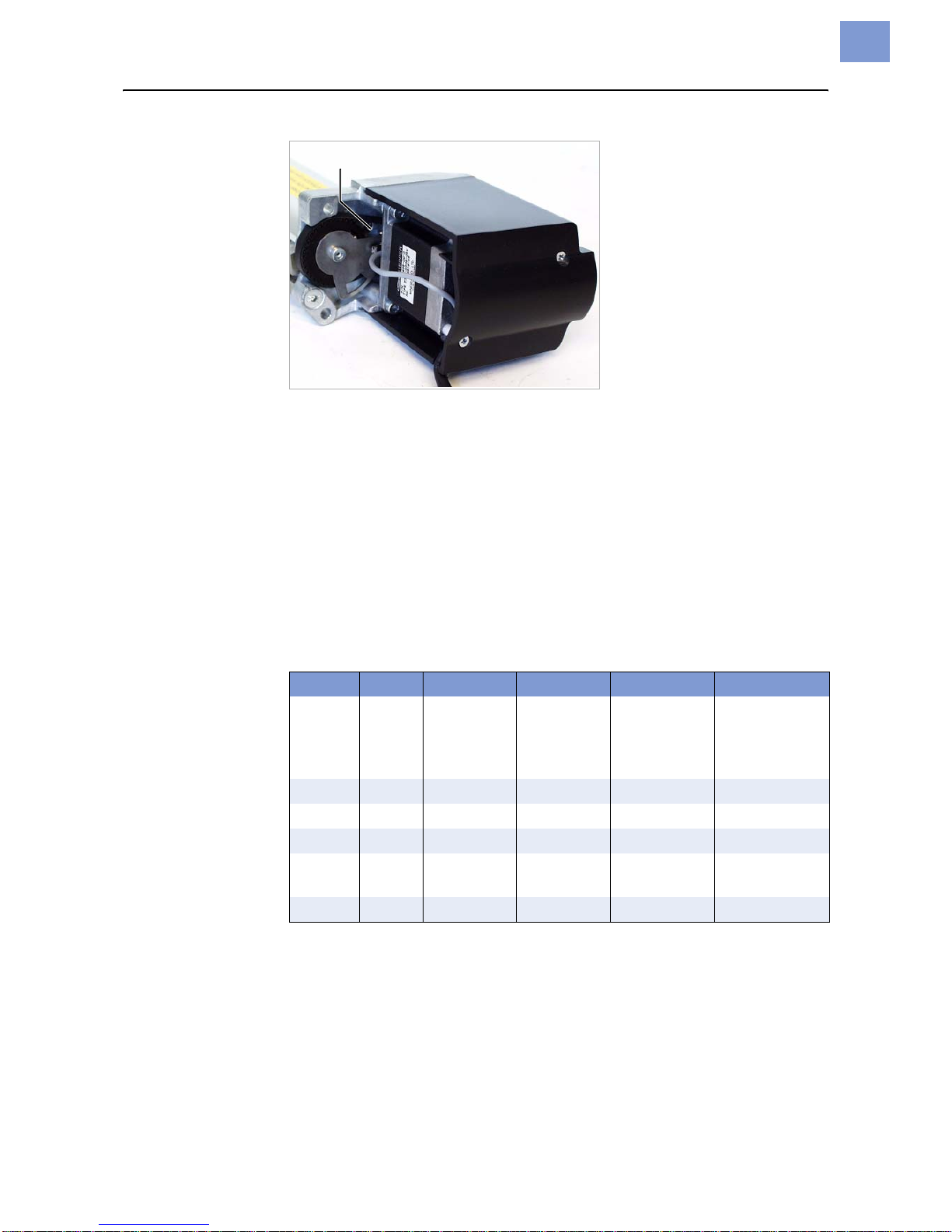
If this status message occurs repeatedly, the cutter light sensor may be dirty
or defective.
«Usecompressedairtoblowthedirt offthelightsensor (1). To do so, unmount
the cutter of the printer (see [1]).
WARNING!
Danger of cutting hands and fingers! Activating a non-existent option (peri-
pheral device) can cause the device to malfunction.
«Never touch the knife blade with your fingers while operating the
cutter/printer.
«Only activate options which are mounted and connected properly.
Status 5005
Cutter
ST14
03/10 Rev. 5.04-01 TECHNICAL MANUAL Connection, Setup, Service
Cutter 2000
8
[1] Unmount the cutter to clean the light sensor (1).
«Check, if the cutter cable is damaged. If so, replace the cable.
«Adjust the oscillator disc (see section “Oscillator disc” – “Setting the oscillator
disc”).
PA complete description of all parameters can be found in the printers user
manual, topic section "Info Printouts and Parameters".
PA list of all status reports can be found in the printers user manual, topic
section “Status Reports”.
Parameter settings
The following parameters govern the cutter function and may need to be
adjusted:
PFor more detailed information, see the chapter "Info Printouts and
Parameters".
¯After a print job has been downloaded, the programmed cut function is
carried out automatically by the device.
TTX 350 TTK 64-xx AP7.t AP 5.4/5.6 Meaning
PEPH PEPH Peripheral
device Peripheral
device Peripheral
device Selection
parameter for
peripheral
devices
CSPD CSPD Cut speed Cut speed Cut speed
CPOS CPOS Cut position Cut position Cut position Cut position
CWID CWID Cut width Cut width Cut width
CDIS CDIS Double cut Double cut Double cut Double cut
function
CMOD CMOD Cut mode Cut mode Cut mode Cut mode
[Tab. 1] Parameters which are important for the cutter function.

03/10 Rev. 5.04-01 TECHNICAL MANUAL Connection, Setup, Service
Cutter 2000
9
Status reports
The following status reports may be displayed in conjunction with the cutter
function:
PFor more detailed information, see the chapter "Status Reports" in the
printers user manual.
PTroubleshooting, see the chapter "Troubleshooting" in the printers service
manual.
Triggering a cut
If the cutter is properly mounted and activated, a cut can be triggered the
following ways:
•Press the Cut button, while the printer is in offline mode.
•Include a cut command in the print job, e.g. by setting the respective
parameter in the Easy Plug #ER command.
TTX 350 TTK 64-xx / AP5.4 / AP5.6 / AP7.t Example, comment
ST14 ST14 5005 Cutter Cutter malfunction
ST68 No peripheral device
preparation
[Tab. 2] Status messages caused by printer operation with cutter.
03/10 Rev. 5.04-01 TECHNICAL MANUAL Connection, Setup, Service
Cutter 2000
10
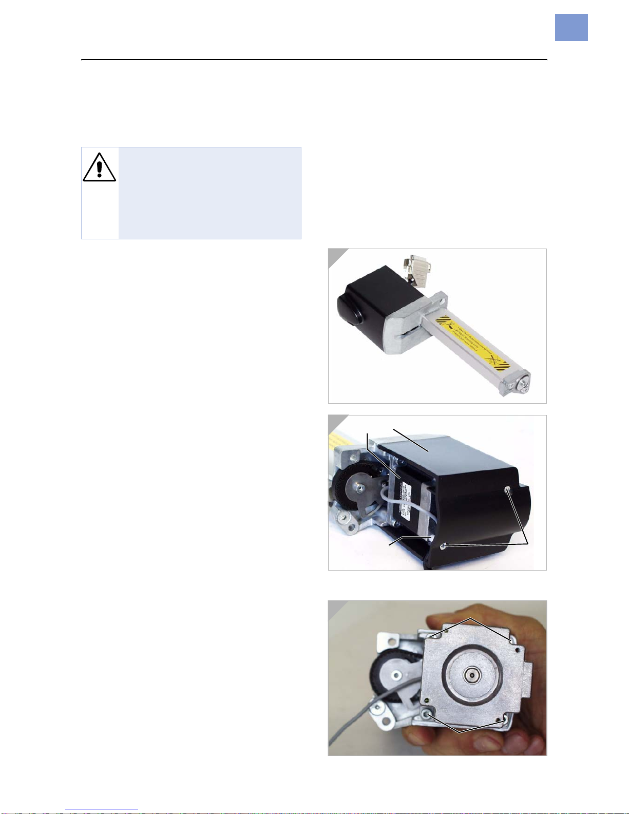
Servicing the cutter
General notes
«Before taking the following steps remove
the entire cutter unit (fig. 1), including the
plug connectors, from the device.
Cutter motor
Almost all service work initially requires dis-
mantling of the cutter motor (1) including
the cutter motor cover (2), as described
below.
Tools
•Phillips screwdriver, small
•Allan key 3mm
Disassembling/assembly
1. Remove the two Phillips screws (3) on the
cutter motor cover. Remove the cover.
¯Donotlose thesleeve(4)whenyoupull
out the screw!
2. Detach the connector cable from the
motor.
3. Unscrew the four screws (5) on the motor
flange. Remove the motor.
WARNING!
Danger of injury! There is a risk of
beingcutwhilecarryingoutservice
work on the cutter!
«Avoid touching the cutter blades.
«Handle the cutter very cautious.
1
2
3
Other manuals for Cutter 2000
1
Table of contents
Other Avery Dennison Printer Accessories manuals

Avery Dennison
Avery Dennison ALS 306 User manual

Avery Dennison
Avery Dennison ALS 104 User manual

Avery Dennison
Avery Dennison Cutter 2000 Guide

Avery Dennison
Avery Dennison SONIC Knife Operating manual

Avery Dennison
Avery Dennison JUNIOR REWINDER Guide
 Monarch 9876 Installation and operation manual")
Avery Dennison
Avery Dennison Mobile Work Station (MWS) Monarch 9876 Installation and operation manual

Avery Dennison
Avery Dennison Monarch AAFES kit User manual

Avery Dennison
Avery Dennison Power Stacker User manual

Avery Dennison
Avery Dennison ALX 720 User manual

Avery Dennison
Avery Dennison Monarch 9433 User manual


