Avery Dennison TTX 450 User manual
Manual Scanner
01/03 Rev. 1.06 1
Manual Scanner
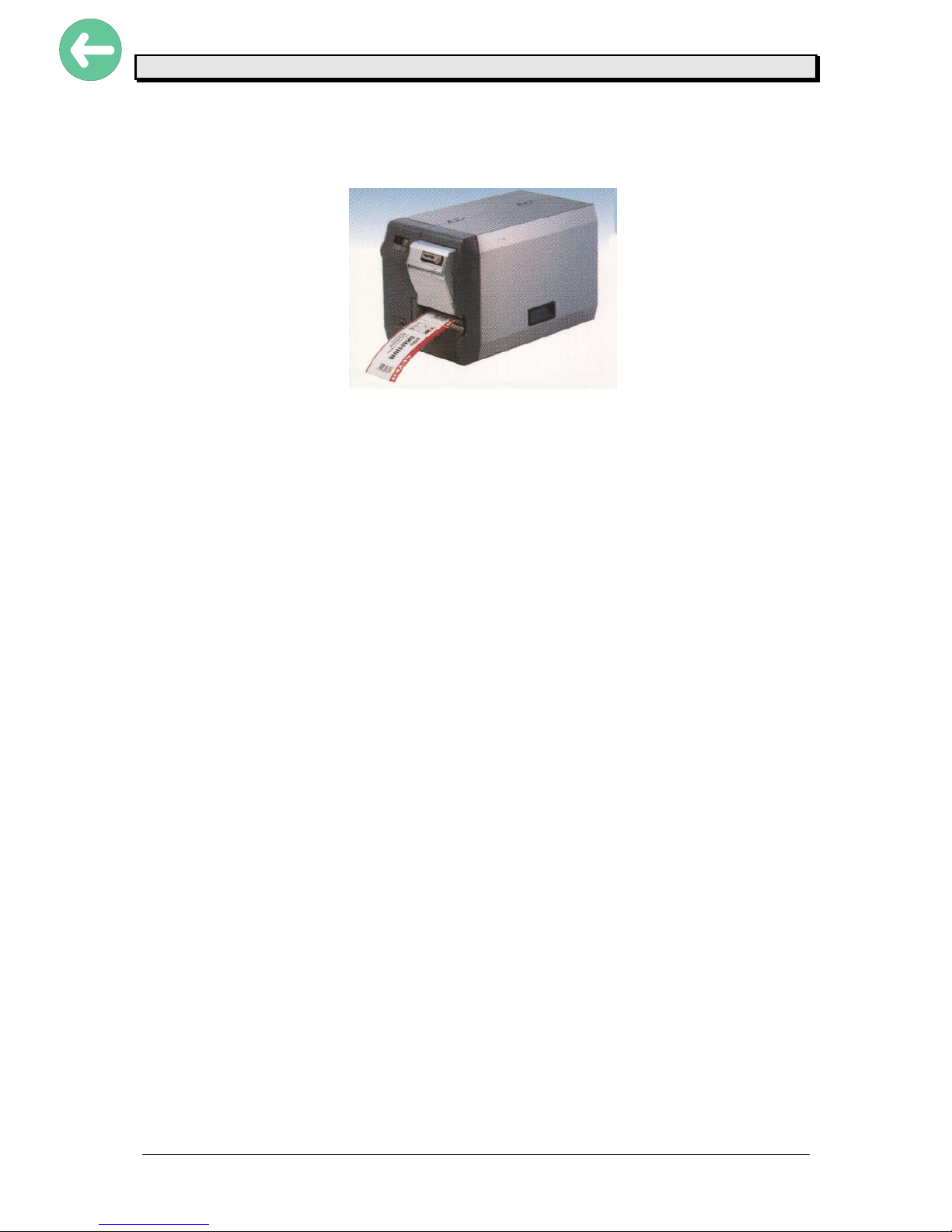
Fig.: TTX 450 with scanner option

Manual Scanner
01/03 Rev. 1.06 2
CONTENTS
IMPORTANT OPERATING INSTRUCTIONS.......................................................................3
Chapter 1 Initiation................................................................................................................4
General scanner information ........................................................................................................... 4
Direction of barcode ..................................................................................................................4
Maximum scan width.................................................................................................................4
Scan Speed...............................................................................................................................5
Setup Scanner................................................................................................................................. 6
Assembly of scanning module...................................................................................................6
Electrical assembly scanner .......................................................................................................... 10
Chapter 2 Set up mode.......................................................................................................11
Scanner activating......................................................................................................................... 11
Activate scanner using the menu ............................................................................................11
Select the scanner .....................................................................................................................11
Mechanical adjustment of the beam..........................................................................................11
Y – direction.............................................................................................................................12
X – direction.............................................................................................................................13
Chapter 3 Modes of operation ............................................................................................14
Scanner Mode ............................................................................................................................... 14
Program the scanner mode.....................................................................................................14
User operation ............................................................................................................................... 14
Error conditions (RAP..............................................................................................................14
Error condition (RBP................................................................................................................15
Multi Colour LED............................................................................................................................ 15
Programming................................................................................................................................. 16
Chapter 4 Information printout / parameter.........................................................................17
Info print out / parameter.........................................................................................................17
Chapter 5 Maintenance and cleaning.................................................................................18
Maintenance and cleaning..................................................................................................19
Cleaning parts are ......................................................................................................................... 19
Chapter 6 Status messages................................................................................................20
Status messages ........................................................................................................................... 20
ST51 scanner is not programmable ........................................................................................20
SCAN barcode not readable in RAP mode .............................................................................20
ST89 barcode information (RBP) not found in data base .......................................................20
ST91 barcode not readable in RBP mode ..............................................................................20
Status reports ................................................................................................................................ 21
Chapter 7 Other ..................................................................................................................25
Parameter Menu............................................................................................................................ 26
Chapter 8 Appendix ............................................................................................................27
Wiring............................................................................................................................................. 28
Spare parts .................................................................................................................................... 29
Index ...................................................................................................................................33

Manual Scanner
01/03 Rev. 1.06 3
IMPORTANT OPERATING INSTRUCTIONS
The following warning hints and precautions contained in these Operating Instructions
must be strictly observed. This will considerable contribute to the safe and expert operation
of your printer.
Warnings: Exclusively original parts and accessories available from the manufacturer are
To be used to maintain the service life of your printer. The use of parts not in
compliance with the exacting demands made by the manufacturer may result
In unnecessary sources of danger.
•The housing of the unit must exclusively be opened by authorised technical
personal.
•Insertion/Exchange of foil and material should be carried out only by especially
instructed personnel(Set Up Mode!)
•On operation with open cover, fingers, hair, clothes jewellery, et. may be
caught by and get into the unit in the foil-feed section . Do not expose or operate the unit
to
moisture nor wet conditions.
•Hazard of injury in the initialisation process and during cutting because of
moving
knife!
Attention : This unit is equipped with a Class II Laser product – do not stare into the
beam !
•Remove printhead not until 3 minutes after disconnection of unit.
•Re connect unit not until 10 seconds after disconnection’s.
•Remove, insert or exchange Plug in Card not until 60 seconds after
disconnection of
unit.
Manual Scanner
01/03 Rev. 1.06 4
Chapter 1 Initiation
General scanner information
It is a scanner we use in the printer line – not a verifier !
The scanner is programmed via the printer – an information regarding barcode and barcode
position
is sent to the scanner. The beam is switched on and the barcode checked for only the
readability !
There is no check for information and no check for the check digit calculation !
Direction of barcode
Only 0 degree and 180 degree barcodes are readable. The scanner can not be rotated to
read 90 degree or 270 degree rotated barcodes.
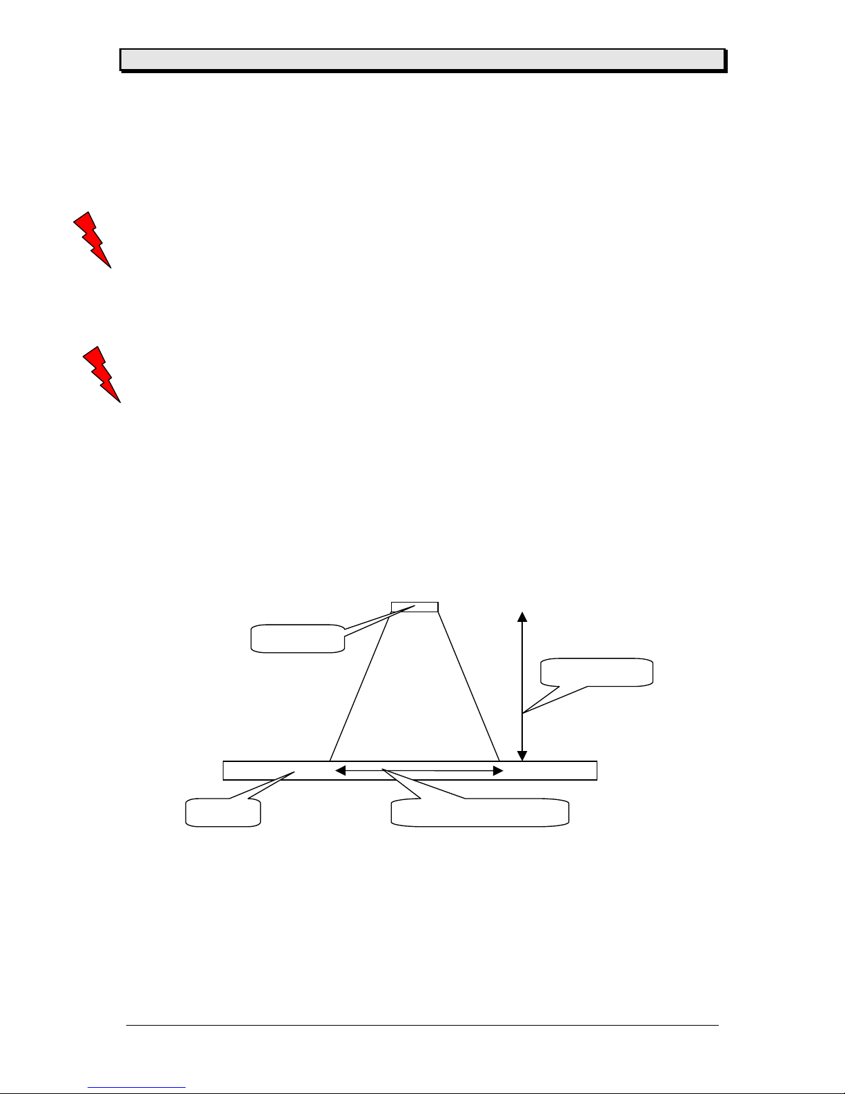
Maximum scan width
Given by the distance between lens and feed roller – the maximum scan width is 3 “ (76,2
mm). he beam is movable across the media width . This distance can not be changed !
distance
scan width 3” (76.2
scanner
label

Manual Scanner
01/03 Rev. 1.06 5
Scan Speed
The used scanner is able to scan 500 codes / second. But have in mind that this is only a
single point – as well the code information has to be send to the scanner (via printer) the
control of the scanner is done by the printer and needs time.
The printer program controls how often a scan can be without success before an error is
shown in the display.

Manual Scanner
01/03 Rev. 1.06 6
Setup Scanner
This chapter is explaining the mechanical assembly – the electrical wiring and the firmware
installation (selecting the peripheral ) !
Attention : Before starting with this work – switch of the unit and unplug from main
power supply !
Assembly of scanning module
To get the serial number – the dispensing module can be mounted to the printer – call the
factory or your service technician. Secure you can mount the scanner from serial number
05450xxxx-xxx ! Please use only the newest firmware.
•remove cap to open the hole where the cable will go trough
Manual Scanner
01/03 Rev. 1.06 7
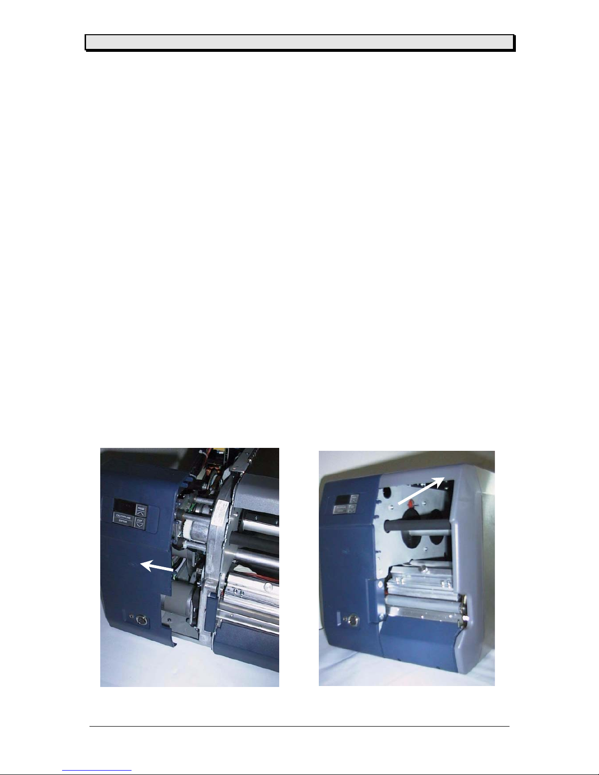
•open rear cover ( 6 cross recessed screws) – carefully watch the wiring of the fan
•loosen the left front cover and move it slightly away, still connected to the board ! Remove
the right front cover and replace it with the new one – remove as well the name plate from
the old cover
Manual Scanner
01/03 Rev. 1.06 8
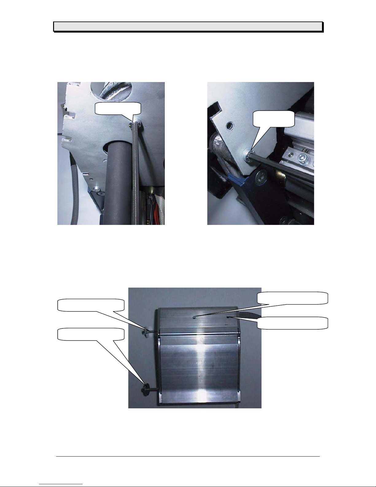
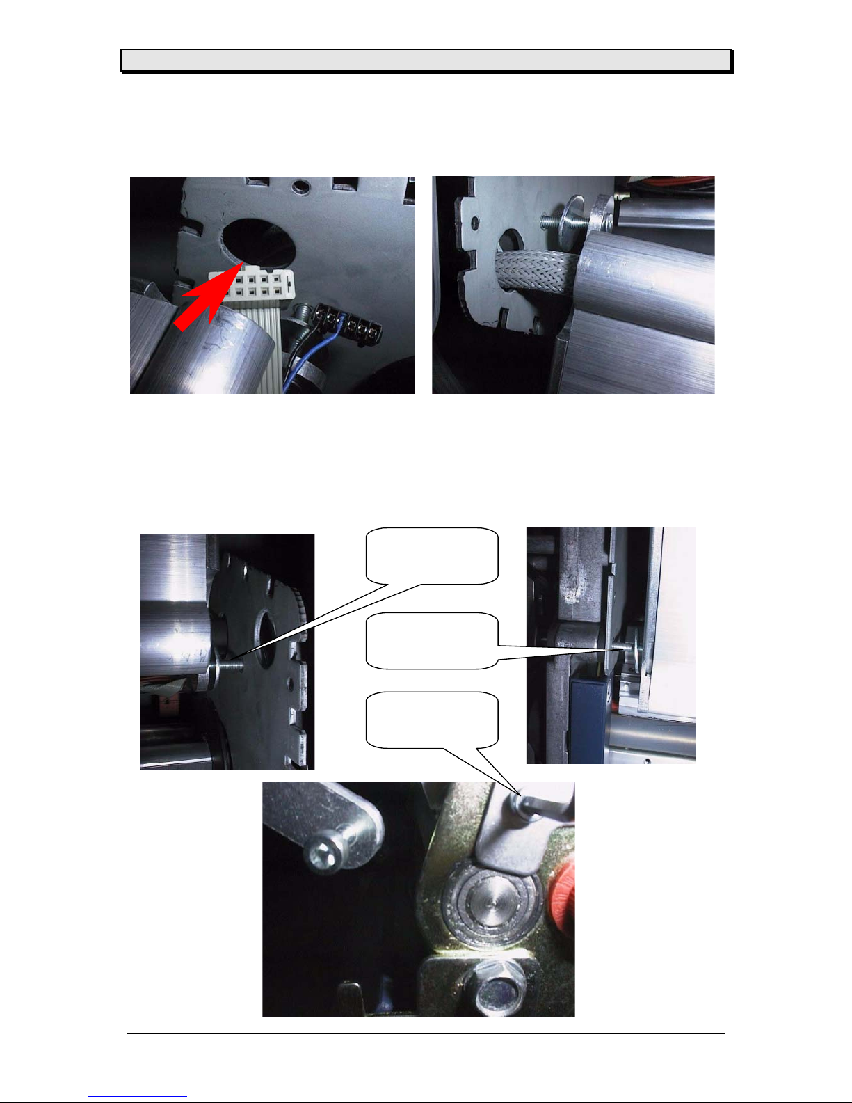
•open the two screws shown on the pictures – the print module is fixed to the base plate
with these screws (2 out of 5)
•remove the screws – they will be replaced by two new screws out of the assembly set of
the scanner module, length and screw head are different . There is a third screw to replace
on the next page.
•mount the removed logo plate to the scanner module using the two fixation holes shown on
the picture below
screw 1
screw 2
screw set 1
screw set 2
logo plate hole
logo plate hole
Manual Scanner
01/03 Rev. 1.06 9
•move the shielded scanner cable through the open hole – guide only one connector at one
time through the hole
•assemble the scanner module to base plate and print module – Attention : Use the new
screws. This is shown on picture 1 and picture 2. The third screw you have to change is
placed in front of the feed unit – shown on picture three – the new screw is as well supplied
with the assembly set
picture 1
screw 1
picture 2
screw 2
picture 3
screw 3

Manual Scanner
01/03 Rev. 1.06 10
Electrical assembly scanner
As soon as the scanner module is assembled mechanically – the electrical wiring can be
done. Adjustment and programming of the scanner is shown under the point scanner
activating (see modes of operation chapter 3)
•the scanner (nr. 99171-xx to 99173-xx) – and the scanner cable (nr. 99183-xx) is equipped
with a serial connector and a power connector
•to integrate the scanner means that the scanner is using the serial interface of the printer !
That results in maybe only removing the original connector from the CPU board (CN 13) or
removing the complete cable what we recommend ! If you remove the cable, you have to
close the slot on the back side of the printer with the supplied metal plate again (reason is
properly shielding the printer).To connect the power supply to the scanner use the
connector with the two wires and plug into the I/O board (CN26) – the other end of the cable
is mounted to the scanner connector !
Attention: Please mount the cover plate on the serial slot if you remove the serial
cable ! Otherwise you will loose the CE certification.
•insert the plugs into the shown connectors on the CPU and I/O board
serial connector CN13 power supply CN26

Manual Scanner
01/03 Rev. 1.06 11
Chapter 2 Set up mode
Scanner activating
Activate scanner using the menu
After the scanner has been mechanically and electronically assembled – the printer has to be
programmed to use the scanner correct, the scanner beam has to be adjusted to scan on the
right place (in y and x direction) !
This can be done only by trained people !
Select the scanner
•using CODE (FEED, CUT, ON/OFF, ON/OFF, FEED, CUT) go into the service
menu
•select ACSC
•set ACSC to YES (select Scanner)
•press ENTER the printer is reset - INIT is flashing (for a longer time than
usual)
Mechanical adjustment of the beam
The scanner has to be adjusted mechanically ! Having in mind that the beam should work as
well if an option (like cutter) is mounted, and that the beam window has not the same width
then the printer, the scanner has to be adjusted in y and x direction.
Attention : To adjust the scanner – the beam has to be ON ! Follow the next steps carefully
to switch on the beam.
•equip printer with ribbon
•insert media into the printer (best joyce would be a white one)
•enter the menu and go to menu point OTHR
•select ADJS
•select SON – press ENTER the beam is switched on constantly, the display
shows SOFF – to switch off the beam you have to press ENTER again
•follow the steps to adjust the scanner – then switch off the beam (ENTER)
Manual Scanner
01/03 Rev. 1.06 12
Y – direction
To be able to adjust the scanner the beam has to be ON !
This adjustment can be done by opening the front cover of the scanner module by hand (see
picture)
You will see the scanner mounted to a base plate. The base plate is mounted to the side
plates with 4 screws. Loosen that screws and adjust the beam by moving the base plate
forwards / backwards until the beam is in the middle between printhead and an option (like
cutter). The beam should be visible on the paper. Control – and if OK fix the screws again.
The next step is the adjustment in X direction !
Scanner
feed roller
Y
- direction
Beam
adjustment adjustment
adjustment adjustment

Manual Scanner
01/03 Rev. 1.06 13
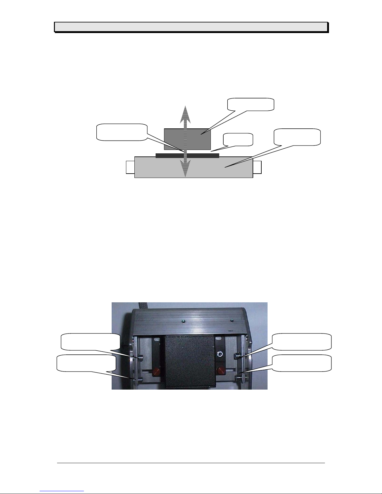
X – direction
Attention : The width of the beam 3” or 76,2 mm can not be extended – it is given by the
mechanical distance between lens and feed roller (or label surface)!
This adjustment can be done by opening the front cover of the scanner module by hand (see
picture)
You will see the scanner mounted to a base plate. As well you ill see two red knurled screws
. Loosen them and you can move the scanner in x direction across the base plate to the left
and right. Adjust the beam to the place where you want to read the barcode. Depending on
the printer, beam window and print width can be different.
Attention : Never look into the beam – nor remove the scanner from the base plate with
power on and the beam ON ! Do not point out with the scanner to other people
– they or you could be hurt.
Scanner
f
eed roller
x - direction
Beam width 3”
Scanner
knurled screw
knurled screw

Manual Scanner
01/03 Rev. 1.06 14
Chapter 3 Modes of operation
Scanner Mode
Depending on the use of your system, the scanner is able to operate in two different modes –
they are called read before print (RBP) and read after print (RAP) !
Using the scanner in the RBP mode the infeed module is mounted to the printer. A single
label is introduced into that module in front of the printer. This label is pre printed with a
barcode and the scanner is reading this code. The information, stored in the code, is
transferred into the printer.
An internal data base stored on a special card (called data base card) will be checked for a
matching data stream, if a match is found the data stream information is printed to the label .
To get more information please refer to the card manual.
Using the scanner in the RAP mode – the code is printed by the printer and after that the
scanner is checking the readability (not verify – only read !) .
Not using the scanner you can deselect it – set the menu point to OFF !
Program the scanner mode
•enter the menu and go to SYSP
•select SCAN
•select the mode you want to work with (RAP or RBP or OFF)
•accept and go out
User operation
To use the scanner now in the defined mode – you have to program the scanner with the
information regarding barcode type – quantity of barcodes on the label – length of the code
and so on. This is done by sending a special EASY PLUG command to the printer. As well
the error condition has to be programmed.
Error conditions (RAP
•enter the menu and go to SYSP
•select SERR
•adjust the reaction by selecting the correct value
1 =as soon as the scanner is unable to read a code an error shows up
noise and optic
2 =having two invalid scans one after another an error shows up
.....
9 =a maximum of nine invalid scans can result in an error
•accept and leave the menu
Optical error message SCAN

Manual Scanner
01/03 Rev. 1.06 15
Error condition (RBP
An invalid – not readable barcode results in the message
Optical error message ST 89
Multi Colour LED
The scanner has a multi colour LED at the rear end of the unit. That provides you with
operational information.
The followings are descriptions of each LED :
LED is blinking yellow
The scanner is powered, not triggered and is funtioning normally.
LED is solid yellow
The scanner is triggered or the unit is in continuous read mode.
LED is green for ½ second
Scanner has successfully decoded a barcode.
LED is red for ½ second
Scanner has not successfully decoded a barcode.
LED flashes is red, yellow and green
Setup mode.
LED is solid red or flashing in red
The scanner has detected a mail function – please call the service.

Manual Scanner
01/03 Rev. 1.06 16
Programming
Using a special EASY PLUG command the scanner is programmed. The syntax for the
command is described below. A maximum of 8 codes can be programmed on one label (n)
this must be at least the quantity of activated codes (a, b, c ...). The command can be
used only outside of the format commands #ER ... #Q !
Getting the error message ST 51 on the display means that the printer could not
communicate with the scanner. Check the wiring and the scanner.
After accepting the error message the printer is LOCKED. To solve that switch OFF/ON the
printer.
Attention : The following characters STX (02h) ETX (03h) and EOT (04h) can not be
used in the codes ! Jetmark / Aragon or MVT 3 can not use this command.
The command is stored in the scanner until a new #PS command is send.
Syntax : #PSa/w/b/x/c/y/d/z/n
a, b,c,d Easy Plug number of the code
w,x,y,z number of characters in the code (0 =variable code length)
n quantity of codes on the label
Barcode Easy Plug Number Number for Scanner
no Code
EAN-8 0 0
EAN-13 1 1
UPCA 2 2
Code 93 3 3
2/5I 4 4
Code 39 (2:1) 7 7
Codabar 8 8
UPCE 9 9
Code 128 13 13
Code 39 (3:1) 16 7
Other codes can not be used !
If there are more codes of the same type on the label – with the same length or variable code
length is programmed - and all of them should be checked, it is sufficient to activate the code
only once. The quantity of codes is shown by the nabove.
Example: #PS7/10///////2label with two barcodes code 39 – 10 characters
Attention: If more then one code of the same type is activated on a label – the code
information must be different !

Manual Scanner
01/03 Rev. 1.06 17
Chapter 4 Information printout / parameter
Info print out / parameter
Not valid

Manual Scanner
01/03 Rev. 1.06 18
Chapter 5 Maintenance and cleaning

Manual Scanner
01/03 Rev. 1.06 19
Maintenance and cleaning
Cleaning parts are
•standard printer parts (see manual)
•the lens of the scanner (regular)
Attention : Do not clean the lens with power ON and beam ON – do not stare into beam –
this could hurt you.

Manual Scanner
01/03 Rev. 1.06 20
Chapter 6 Status messages
Status messages
ST51 scanner is not programmable
wrong command sequence
check wiring between scanner and printer
check scanner
SCAN barcode not readable in RAP mode
check print quality
ST89 barcode information (RBP) not found in data base
check data base and data base card
ST91 barcode not readable in RBP mode
check print quality
Other manuals for TTX 450
1
Table of contents


