AVGear AVG-PSU12-UL User manual

AVG-PSU12-UL
Features
▪Dual input channel designed for
ensuring a stable AC power source.
▪12 Output channels, each channel has
three options for output voltage
(5/12/24V).
▪Output channels can be switched on
and off via the Front panel, RS232,
GUI and TCP/IP.
▪Output voltage (5/12/24V) can be
selected via the TACT switches on the
rear panel, RS232 or the GUI.
▪Sequential Control technology.
▪Supports online firmware updates.
The PSU12-UL is an integrated switching
power supply designed for converting AC into
DC power. It features 2 input channels and 12
output channels, input voltage 100-240VAC,
output 5/12/24VDC.
Using the built in sequential control technology,
when powered on, the 12 output channels will
turn on in sequence with a 100ms delay
between.

AVG-PSU12-UL
PLEASE READ THIS PRODUCT MANUAL CAREFULLY
BEFORE USING THIS PRODUCT.
This manual is only for operation instruction only, and
is not to be used in a maintenance capacity. The
functions described in this version are current as at
October 2017. Any changes of functions and
operational parameters will be updated in future
manual versions. Please refer to your dealer for the
latest product details.
Version 1.0 23/10/17
AVG-PSU12-UL
SAFETY OPERATION GUIDE
In order to guarantee the reliable operation of the equipment and safety of the
user, please abide by the following procedures in installation, use and
maintenance:
1. The system must be earthed properly. Please do not use two blade plugs
and ensure the AC power supply ranges from 100v to 240v and from 50Hz
to 60Hz.
2. Do not install the switcher in an environment where it will be exposed to
extreme hot or cold temperatures.
3. This unit will generate heat during operation, please ensure that you allow
adequate ventilation to ensure reliable operation.
4. Please disconnect the unit from mains power if it will be left unused for a
long period of time.
5. Please DO NOT try to open the casing of the equipment, DO NOT attempt to
repair the unit. Opening the unit will void the warranty. There are high
voltage components in the unit and attempting to repair the unit could result
in serious injury.
6. Do not allow the unit to come into contact with any liquid as that could result
in personal injury and or product failure.

AVG-PSU12-UL
TABLE OF CONTENTS
Introduction ..............................................................................................................1
Introduction to the AVG-PSU12-UL..............................................................1.1
Features .......................................................................................................1.2
What’s in the Box ........……………………………………………………………………2
Product Appearance of the AVG-PSU12-UL ..........................................................3
System Connection..................................................................................................4
Usage Precautions.......................................................................................4.1
Connection Diagram.....................................................................................4.2
Connection Procedure..................................................................................4.3
System Applications.....................................................................................4.4
System Operations...................................................................................................5
Front Panel Control ......................................................................................5.1
RS232 Control..............................................................................................5.2
Installation/Removal of the RS232 Control Software......................5.2.1
Basic Settings.................................................................................5.2.2
RS232 Communication Commands................................................5.2.3
GUI Control...................................................................................................5.3
Control Menu..................................................................................5.3.1
Voltage Setting Menu......................................................................5.3.2
Netwrok Menu.................................................................................5.3.3
Password Menu..............................................................................5.3.4
GUI Update.....................................................................................5.3.5
Specifications...........................................................................................................6
Panel Drawing ..........................................................................................................7
Troubleshooting & Maintenance.............................................................................8

AVG-PSU12-UL
1. Introduction
1.1. Introduction to the AVG-PSU12-UL
The PSU12-UL is an integrated switching power supply designed for converting AC
into DC power. It features 2 input channels and 12 output channels, input voltage
100-240VAC, output 5/12/24VDC.
Using the built in sequential control technology, when powered on, the 12 output
channels will turn on in sequence with a 100ms delay between. In addition each
output channel can be switched on/off via the front panel,
1.2. Features
▪Dual input channel designed for ensuring a stable AC power source.
▪12 Output channels, each channel has three options for output voltage
(5/12/24V).
▪Output channels can be switched on and off via the Front panel, RS232, GUI
and TCP/IP.
▪Output voltage (5/12/24V) can be selected via the TACT switches on the rear
panel, RS232 or the GUI.
▪Sequential Control technology.
▪Supports online firmware updates.

AVG-PSU12-UL
2. What’s in the Box
▪1 x AVG-PSU12-UL Integrated Switching Power Supply
▪2 x Mounting ears (6 x Screws)
▪4 x Rubber Feet
▪2 x Power Cords
▪12 x DC Power Cables (2 pin Phoenix Plugs)
▪12 x 2 pin Phoenix Connectors
▪1 x 3 pin Phoenix Connector
▪1 x RS232 Cable (DB9 to 3 pin Phoneix Connector)
▪1 x User Manual
Note: Please immediately contact your distributor if you found any damage or defect
in the components.

AVG-PSU12-UL
3. Product Appearance of the AVG-PSU12-UL
Front Panel
No
Name
Description
①
Firmware
Micro USB port for updating firmware.
②
AC1 & AC2
Input AC source indicators.
▪Green when device is powered on and is in
normal output.
▪Red when there is no power to the device.
▪Orange when the input voltage is too low or too
high.
③
01 - 12
Output channel switching buttons and activity LEDs,
12 in total.
▪Press the button to turn the corresponding
channel on or off. The corresponding LED will
change to green when the channel is on.
▪A long press for 3 seconds or more will
lock/unlock the channel, the corresponding LED
will flash 3 times.
Note: Pictures shown in this manual are for reference only.
AVG-PSU12-UL
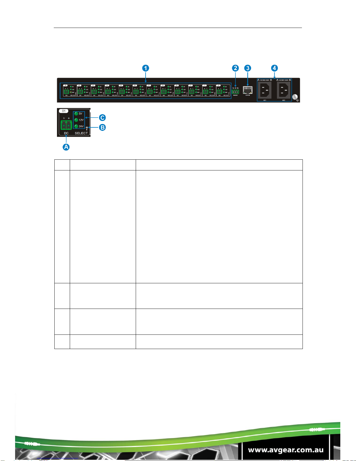
Rear Panel
No
Name
Description
①
01 - 12
12 output channels.
A. DC: 2 Pin Phoenix connector, connect to the
device that reuires power. Eg. AVG-HD300SR
B. SELECT: Press the TACT button to select the
output voltage, options are 5V, 12V and 24V.
A long press of the TACT button for 3 secs or
more, will restore it to factory settings.
C. 5V / 12V / 24V indicators:
▪Green when the selected output voltage
is working normally.
▪Blinking slowly when the current
channel is closed.
▪Blinking fast when the current channel
is in a short circuit state or over voltage.
②
RS232
Serial Port, 3 pin Phoenix connector. Connect your
control device such as a 3rd party control system or
PC.
③
TCP/IP
Ethernet port, connect to your local network or
directly to a PC to control the AVG-PSU12-UL via its
GUI.
④
AC1 & AC2
2 AC input channels. Input voltage is AC100-240V.
AVG-PSU12-UL
4. System Connection
4.1 Usage Precautions
▪System should be installed in a clean environment with temperature and
humidity maintained to within equipment specifications.
▪All of the power switches, plugs, sockets and power cords should be insulated
and safe.
▪All devices should be connected before power is turned on.
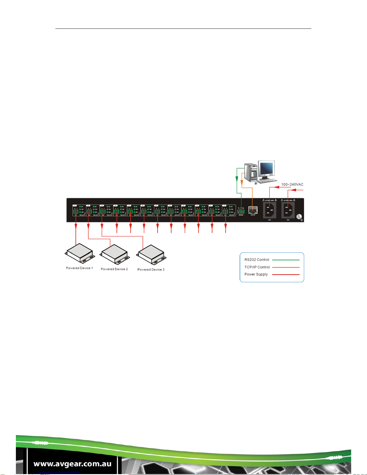
4.2 Connection Diagram

AVG-PSU12-UL
5. System Operations
5.1 Front Panel Control
The front panel features four input and output selection buttons for switching the I/O
connection.
▪Switch on/off output channel:
Press buttons 01 –12 on the front panel to switch the corresponding output
channel.
▪Lock/Unlock output channel:
Long press buttons 01 –12 for 3 seconds or more on the front panel to
lock/unlock the corresponding channel. The corresponding LED will flash 3
times.
Note: The locked channel can’t be controlled via the front panel buttons,
RS232 or the GUI.
▪Select the Output Voltage:
Press SELECT on the corresponding output channel to select the output
voltage as 5V, 12V or 24V.
Note: After switching the output voltage, the output channel will be turned off.
This is to protect an over voltage situation on the connected device. Ensure
your device is able to accept the selected voltage and turn the output on via
the front panel.
▪Restore Factory defaults:
On the rear panel, simultaneously long press SELECT on channel 1 and
channel 2 for 3 seconds or more. The device will be restored to factory
settings.
5.2 RS232 Control
5.2.1 Installation/removal of RS232 Control Software
▪Installation Copy the control software file to the computer controlling the
Integrated Switching Power Supply.
▪Removal Delete all the control software files in corresponding file path.
5.2.2 Basic Settings
Here we use the software CommWatch.exe as an example. The icon is shown as
below:
Icon of CommWatch

AVG-PSU12-UL
The interface of the control software is shown below:
Set the parameters (baud rate, data bit, stop bit and parity bit) correctly to ensure
reliable RS232 control.
Baud rate: 9600 Data bit: 8 Stop bit: 1 Parity bit: none
5.2.3 RS232 Communication Commands
1) “[“, “]” in the commands are for easy recognition only and not necessary in real
operations. Other symbols including “.”, “,”, “/”, “%”, “;”, “^”. are parts of the
commands.
2) The feedback listed in the column “Feedback Example” is only for reference,
feedbacks may vary according to different operations and firmware.
System Commands
Command
Function
Feedback Example
All@.
Switch on all outputs
All Open.
All$.
Switch off all outputs
All Closed.
[x]@.
Switch on the output channel [x], x = 1 –12
[x] Open.
[x]$.
Switch off the output channel [x], x = 1 –12
[x] Closed.
Output/[x]V/[y].
When y = NULL, Set the output voltage as x for all
output channels.
X = 5/12/24
All Output [x]V.
When y = 1 - 12, Set the output voltage as x for
the output channel y.
[y] Output [x]V.
Parameter Configuration
area
Monitoring area,
indicates whether the
command sent works.
Command Sending area
AVG-PSU12-UL
X = 5/12/24
Status[x].
When x = NULL, query the on-off states of all the
output channels.
01 Open.
02 Closed.
03 Closed.
…
When x = 1 –12, query the on-off state of output
channel x.
[x] Open.
[x] Closed.
Save[x].
Save the current on-off state to Group x.
X = 1 –5
Save to F[x].
Recall[x].
Invoke the on-off states of Group x.
X = 1 –5
If Group x has no data,
the feedback will be:
F[x] no data.
If Group x has data,
the feedback will be:
Out 01 02 03 04 05 06
07 08 09 10 11 12
State S S S S S S S S
S S S S
Vm 12 12 12 12 12 12
12 12 12 12 12 12
Over N N N N N N N N
N N N N
Lock N N N N N N N N
N N N N
Clear[x].
When x = NULL, clear the data of all the Groups.
Clear All.
When x = 1 –5, clear the data of the Group x.
Clear F[x].
QueryGroup[x].
When x = NULL, query all Groups.
Out 01 02 03 04 05 06
07 08 09 10 11 12
Vm1 12 12 12 12 12
12 12 12 12 12 12 12
Vm2 XX XX XX XX XX
XX XX XX XX XX XX
XX
…
When x = 1 –5, query group x.
Out 01 02 03 04 05 06
07 08 09 10 11 12
Vm[x] 12 12 12 12 12
12 12 12 12 12 12 12
%0911.
Restore to Factory defaults.
Factory Default.
%9964.
Query the IP Address
IP xxx.xxx.xxx.xxx
ChangeIP
IP/Mask/Gateway;
Change the IP Address/Subnet Mask/Gateway.
For example:
Change IP
192.168.0.178/255.255.255.0/192.168.0.1;
AVG-PSU12-UL
%9975.
Query the status of all output channels.
Out 01 02 03 04 05 06
07 08 09 10 11 12
State S S S S S S S S
S S S S
Vm 12 12 12 12 12 12
12 12 12 12 12 12
Over N N N N N N N N
N N N N
Lock N N N N N N N N
N N N N
/^Version;
Query the software version.
V x.x.x
Baud[x].
Set the baud rate as x. x = 1200, 2400, 4800,
9600, 19200, 38400, 57600 or 115200.
When x = NULL, the default baud rate is 9600.
Baud [x] not change.
Baud [y] change to [x]
Lock[x].
When x = NULL, lock all the channels.
Locking all channel.
When x = 1 –12, lock channel x.
Locking [x] channel.
Unlock[x].
When x = NULL, unlock all the channels.
Unlocking all channel.
When x = 1 –12, unlock channel x.
Unlocking [x] channel.
LockKeyboard[x].
When x = 0, unlock the front panel.
Unlocking Keyboard.
When x = 1, lock the front panel
Locking keyboard.
Rebootx.
When x = NULL, reboot all output ports;
When x = 1 –12, reboot the output port x.
Rebootx.
Note:
▪After sending the “Output/[x]V/[y].” to change the output voltage, the
corresponding output channel will be switched off, the command “[x]@.” can
be sent to turn the output back on.
▪After sending the “LockKeyboard[x].” to lock the front panel, the device can
still be controlled by RS232 commands and GUI.
AVG-PSU12-UL
5.3 GUI Control
In addition to control via the front panel or RS232 commands, the AVG-PSU12-UL
can also be controlled via a web browser using its GUI.
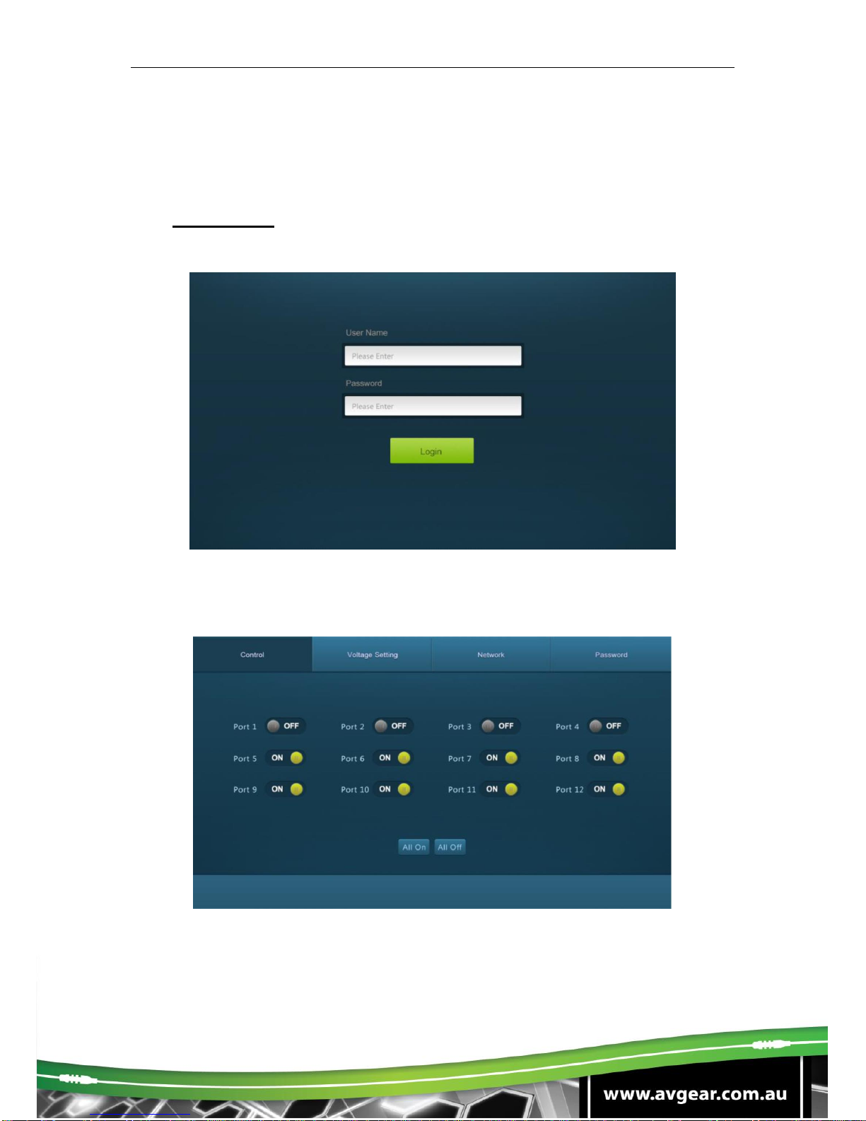
Type 192.168.0.178 (the default IP address) in your browser, it will display the log-in
page as shown below:
5.3.1 Control Menu
Type the user name: user, password: user, and then click LOGIN, it will display the
Scene menu as shown below:
▪Select the ON/OFF to switch on/off the output channel.
▪Click the All On to switch on all output channels.
▪Click the All Off to switch off all output channels.
AVG-PSU12-UL
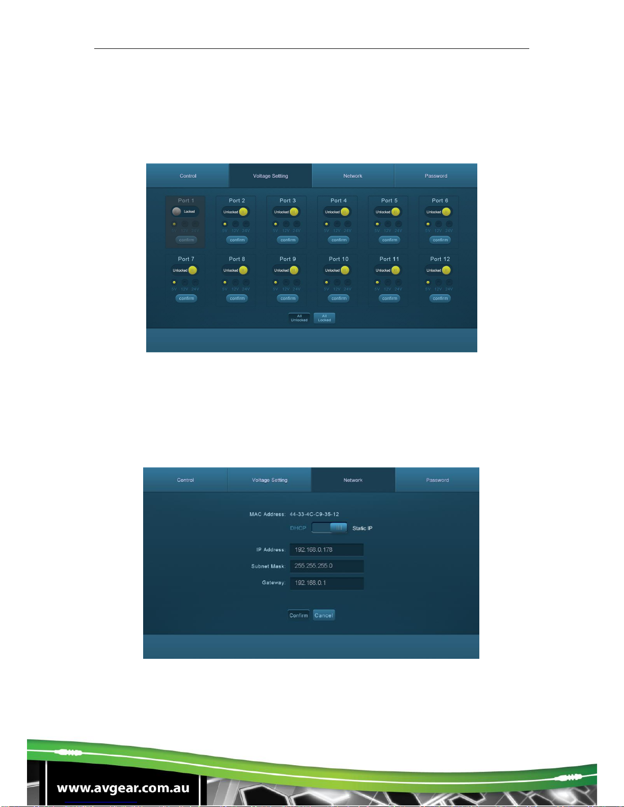
5.3.2 Voltage Setting Menu
Click Voltage setting on the top of the page to access the Voltage setting menu as
below:
▪Lock/Unlock the output channel. When the port is locked, its voltage cannot
be switched.
▪Select 5V, 12V or 24V output voltage for each output channel.
5.3.3 Network Menu
Click “Network” to enter the network setting menu as below:
▪Dynamic or static IP addresses can be selected.

AVG-PSU12-UL
5.3.4 Password Menu
Click the Password on the top of the page to enter the password menu as shown
below:
▪Modify the password as required.
▪Lock/Unlock the Front Panel buttons.
5.3.5 GUI Update
GUI for the Power Switcher supports online update in http://192.168.0.178:100. Type the
username and password (the same as the GUI log-in settings, modified password
will be available only after rebooting) to log in the configuration interface. After that,
click Administration at the source menu to get to the Upload Program as shown
below:

AVG-PSU12-UL
6. Specifications
Input & Output
Input Port
AC1 & AC2
Input Voltage
100~240VAC 50~60Hz
Output Port
Total 12 DC port (2-Pin phoenix connectors)
Output Voltage
5V, 12V or 24V is selectable.
Output Voltage Range
5V: 4.75 ~ 5.25V
12V: 11.4 ~ 12.6V
24V: 22.8 ~ 25.2V
Maximum output power
consumption of signal channel
5V:12W; 12V:15W; 24V:15W
Maximum output power
consumption for single supply
110VAC:90W; 220VAC:180W
Maximum output power
consumption for dual supply
180W
Control Part
Buttons Control
Front Panel: 01 ~ 12, total 12 buttons.
Rear Panel: Total 12 TACT Switches, named
SELECT.
RS232 Control
RS232 port (3-Pin phoenix connector).
Baud rate support 9600.
GUI Control
TCP/IP port (RJ45).
Default IP: 192.168.0.178
Port No.: 4001
General
Temperature
0 ~ +50℃
Humidity
10% ~ 90%
Dimension (W*H*D)
437mm x 44mm x 357mm
Net Weight
4.2Kg
AVG-PSU12-UL
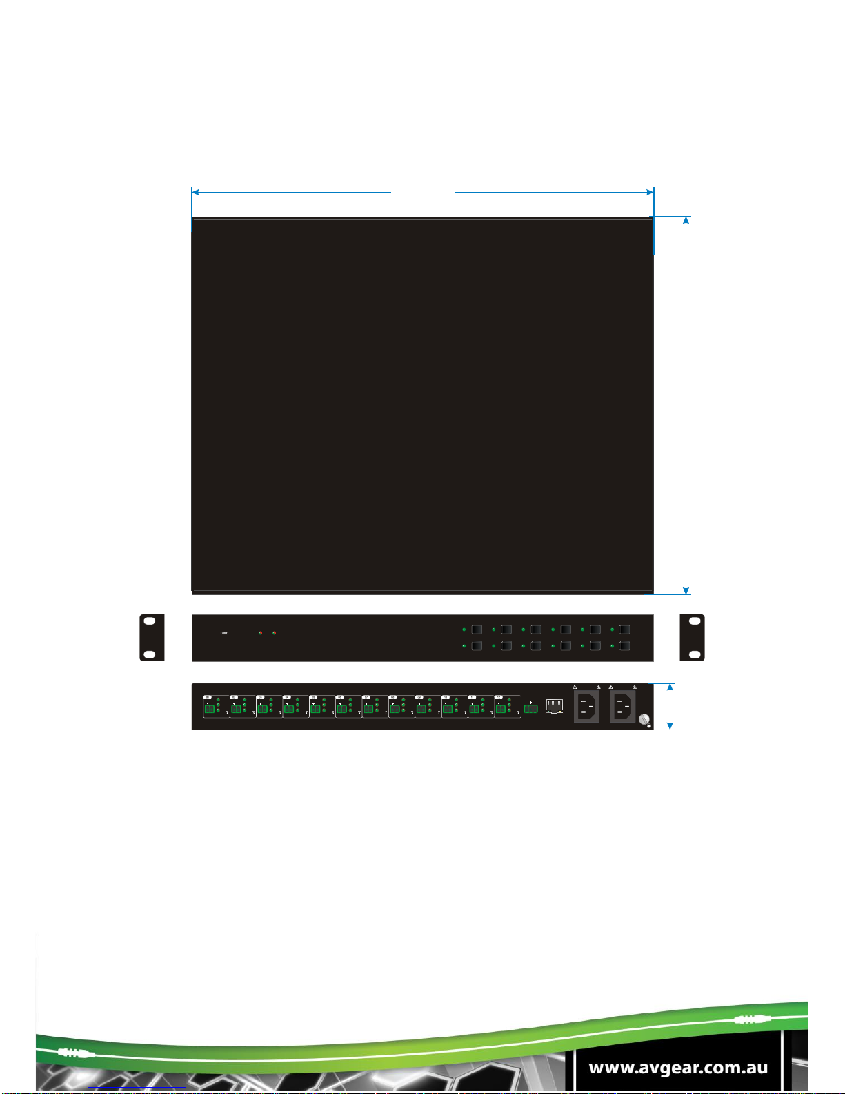
7. Panel Drawing
FIRMWARE
01 02 03 04 05 06
07 08 09 10 11 12
AC 2
AC 1
AC100V 240V-
Tx Rx
RS232 TCP IP/
24V
AC100V 240V-
AC1 AC2
DC
12V
5V
++
SELECT
24V
DC
12V
5V
SELECT
24V
DC
12V
5V
SELECT
24V
DC
12V
5V
SELECT
24V
DC
12V
5V
SELECT
24V
DC
12V
5V
SELECT
24V
DC
12V
5V
SELECT
24V
DC
12V
5V
SELECT
24V
DC
12V
5V
SELECT
24V
DC
12V
5V
SELECT
24V
DC
12V
5V
SELECT
24V
DC
12V
5V
SELECT
+ + + + + + + + + + + +
437 mm
357 mm
44 mm

AVG-PSU12-UL
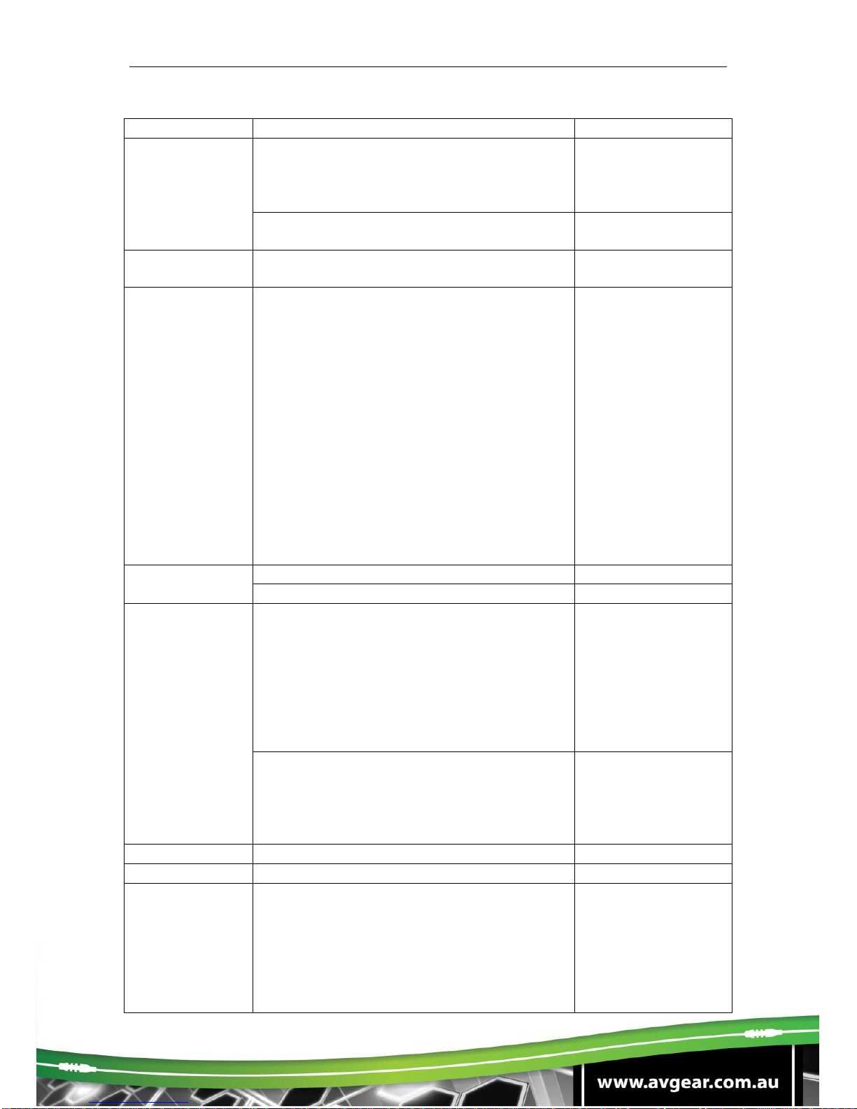
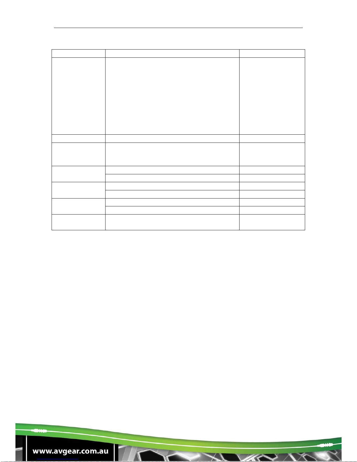
8. Troubleshooting & Maintenance
Problems
Causes
Solutions
No output voltage
Power supply protect function
will start when over loaded.
Please reduce loads.
After selecting output voltage,
the output channel will switch
off automatically.
Switch on the output channel via front
panel button.
Fail or loose connection
Make sure the connection is good.
AC1 or AC2
indicator doesn’t
work or respond
to any operation
Failed connection of the
power cord.
Make sure the power cord connection is
good.
Cannot control
the device by
control device
(e.g. a PC)
through RS232
port
Wrong RS232
communication parameters
Type in correct RS232 communication
parameters.
Fail or loose connection
Make sure the connection is good.
Broken RS232 port
Send it to authorised dealer for checking.
CMD ERR
Extra characters like line feed or carriage
return have been added to the
command, remove them.
Cannot control
the device by
front panel
buttons while can
control it through
RS232 port
The front panel buttons are
broken
Send it to authorised dealer for repair.
Cannot control
the device via
GUI
The IP address of control PC
and TCP/IP port are not on
the same network segment
Modify control PC’s network segment to
the same with the TCP/IP port.
The port No. are wrong.
The correct port No. is 4001.
Fail or loose connection
Make sure the connection is good.
Broken TCP/IP port
Send it to authorized dealer for checking.
Table of contents
Other AVGear Power Supply manuals

Popular Power Supply manuals by other brands

Allen-Bradley
Allen-Bradley 1769-PA2K installation instructions

Siemens
Siemens SIMATIC NET PS598-1 Compact operating instructions

Delta Elektronika
Delta Elektronika ES 150 Series product manual

Norden
Norden NVS-AC10003BC user manual

StarTech.com
StarTech.com ATXPOW250PRO Instruction guide

Emerson
Emerson NetSure 211 C23 user manual


