ES150 DELTA ELEKTRONIKA BV
rev. March 2017 OPERATING MAINTENANCE TROUBLE SHOOTING Page 4 - 3
OPERATING AND STORAGE
CONDITIONS
1) TEMPERATURE
°The operating temperature range at full load is -20 to
+50 °C.
°Please note: a lower temperature extends the life
of the power supply.
°The storage temperature range is -40 to +85 °C.
2) HUMIDITY
°During normal operation humidity will not harm the
power supply, provided the air is not aggressive.
The heat normally produced in the power supply will
keep it dry.
°Condensation. Avoid condensation inside the power
supply, break-down could be the result. Condensation
canoccurduringaperiodthepowersupplyisswitched
off (or operating at no load) and the ambient
temperature is increasing .
Always allow the power supply to dry before switching
it on again.
3) GALVANIC INDUSTRY
°For using the power supplies in the galvanic industry it
is strongly recommended to take precautions against
an aggressive environment.
°An aggressive environment with acid, salt, etc. can
harm the electronic components. Sometimes even the
copper traces of the pc-boards dissolve.
°To avoid problems the power supplies should be
mounted in a relative clean room, or mounted in a
cabinet receiving clean air with over pressure.
Or in a cabinet with a heat exchanger.
MAINTENANCE & TROUBLE
SHOOTING
1) GENERAL
°The ES-series power supplies normally need no
maintenance or calibration. Only care must be taken
that the cooling of the unit is not obstructed.
2) NO OUTPUT (normal operation)
°Remove load from output.
°Checkpositionof prog.switches attherearpanel,they
should be on MANUAL.
°Switch on unit.
°Turn both the CV and CC potentiometer a few turns
clock-wise.Avoltageshouldbepresentontheoutput.
3) PROGRAMMING DOES NOT WORK OK
°Check position of prog. switches at rear panel.
°The unit works OK in manual control, but in
programming mode the output voltage / current has a
large error.
Probably the fuse in series with Ø(pin 1) of prog.
connector tripped, the fuse (F7_1 = 650 mA) is a
self-resetting type.
°To check the fuse (F7_1) measure the voltage
between Øand the minus output, during the fault
condition. The voltage should onlybe a few mV, a high
voltage means that an unwanted current is flowing
through pin 1 of the prog. connector.
Please check why current is flowing through pin 1 (see
also next paragraph 4) and fig. 4- 8).
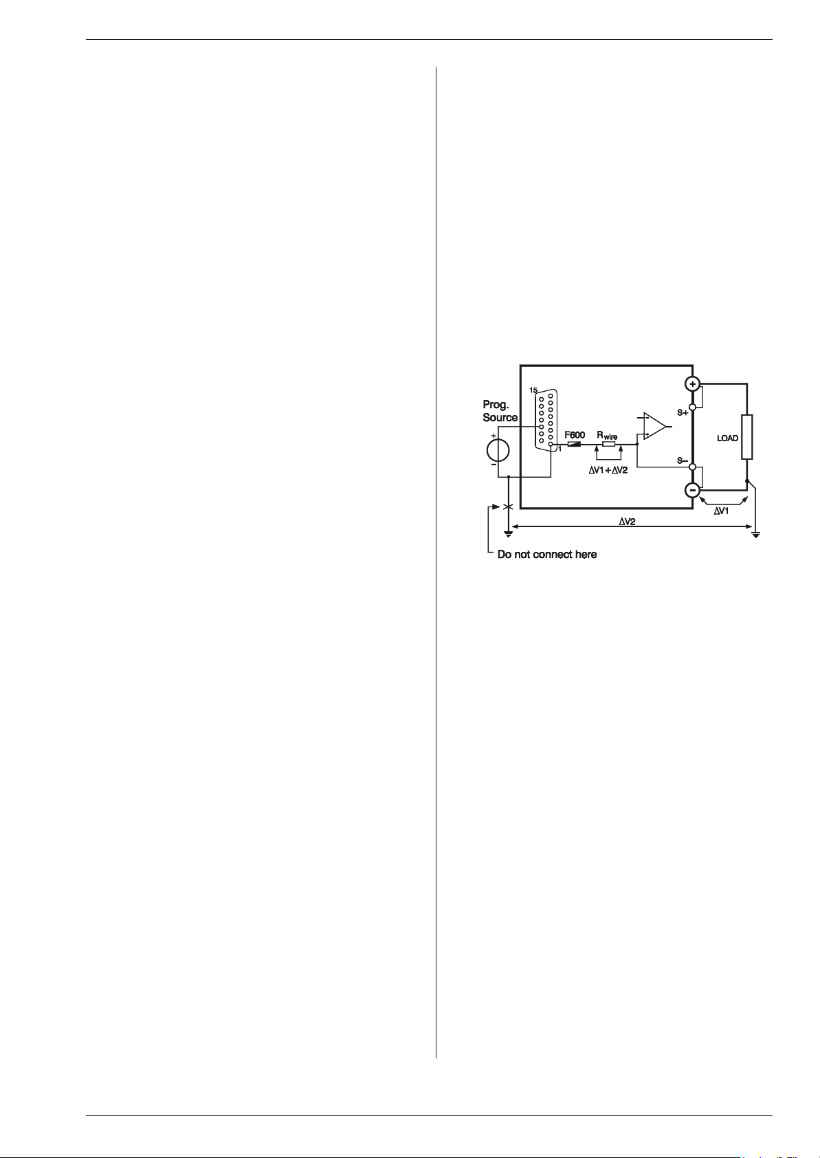
4) PROGRAMMING OFFSETS
°Unwanted offsets in the programming can be
caused by earth loops.
Fig.4-8 showsatypicalearthingproblem.Incasethe
load has a connection to earth and the programming
source as well, problems could occur. Improper
choice of the earthing point of the load can give a
voltage drop of ∆V1. Connecting the minus or zero to
aseparateearthconnectioncangiveavoltagedropof
∆V2. Because the internal wires of the programming
input are thin, the voltage drops ∆V1 and ∆V2 will be
accrosstheinternal wiringaswell.Resulting ina error
voltage in series with the programming voltage.
°The best solution for this is using a floating program-
ming source with the help of the ISO AMP MODULE
(δ-product) or a floating load.
5) STATUS OUTPUT FAILS
°Check fuse F7_2 in series with Ø(pin 8 of program-
ming connector). To check the fuse measure the
resistance between Øand the minus output, an open
circuit means a blown fuse. F7_2 = 650 mA.
6) MASTER / SLAVE PARALLEL PROBLEMS
°Accidental interruption of aminus lead ofa unit during
operation will cause fuse F7_1 to blow. To check the
fuse, measure the resistance between Ø(pin 1 of
prog. conn.) and the minus output, the fuse is a self
resetting type. F7_1 = 650 mA
°Check link between pin 9 and 11 on the programming
connector of the slaves.
7) NO LEDS on.
°Overheatingcanbethecause,cooling downwillreset
the thermal protection.
°Check input power.
°Check fuses inside unit.
fig. 4- 8
Unwanted programming offsets


