Avid Technology FC726 User manual

FC726 Guide
System 5

Legal Notices
This guide is copyrighted ©2011 by Avid Technology, Inc., (hereafter “Avid”), with
all rights reserved. Under copyright laws, this guide may not be duplicated in
whole or in part without the written consent of Avid.
003, 96 I/O, 96i I/O, 192 Digital I/O, 192 I/O, 888|24 I/O, 882|20 I/O,
1622 I/O, 24-Bit ADAT Bridge I/O, AudioSuite, Avid, Avid DNA, Avid Mojo,
Avid Unity, Avid Unity ISIS, Avid Xpress, AVoption, Axiom, Beat Detective,
Bomb Factory, Bruno, C|24, Command|8, Control|24, D-Command, D-Control,
D-Fi, D-fx, D-Show, D-Verb, DAE, Digi 002, DigiBase, DigiDelivery, Digidesign,
Digidesign Audio Engine, Digidesign Intelligent Noise Reduction, Digidesign
TDM Bus, DigiDrive, DigiRack, DigiTest, DigiTranslator, DINR, DV Toolkit,
EditPack, Eleven, HD Core, HD I/O, HD MADI, HD OMNI, HD Process, Hybrid,
Impact, Interplay, LoFi, M-Audio, MachineControl, Maxim, Mbox,
MediaComposer, MIDI I/O, MIX, MultiShell, Nitris, OMF, OMF Interchange, PRE,
ProControl, Pro Tools, Pro Tools|HD, QuickPunch, Recti-Fi, Reel Tape, Reso,
Reverb One, ReVibe, RTAS, Sibelius, Smack!, SoundReplacer, Sound
Designer II, Strike, Structure, SYNC HD, SYNC I/O, Synchronic, TL Aggro,
TL AutoPan, TL Drum Rehab, TL Everyphase, TL Fauxlder, TL In Tune,
TL MasterMeter, TL Metro, TL Space, TL Utilities, Transfuser, Trillium Lane Labs,
Vari-Fi, Velvet, X-Form, and XMON are trademarks or registered trademarks of
Avid Technology, Inc. Xpand! is Registered in the U.S. Patent and Trademark
Office. All other trademarks are the property of their respective owners.
Product features, specifications, system requirements, and availability are
subject to change without notice.
Guide Part Number 9329-65139-00 REV A 08/11
Documentation Feedback
We are always looking for ways to improve our documentation. If you have
comments, corrections, or suggestions regarding our documentation, email us

Contents iii
Contents
Chapter 1. Introduction to the FC726 . . . . . . . . . . . . . . . . . . . . . . . . . . . . . . . . . . . . . . . . . . . . . . . . . . . . . . . . . . . . . . 1
Basic Concepts . . . . . . . . . . . . . . . . . . . . . . . . . . . . . . . . . . . . . . . . . . . . . . . . . . . . . . . . . . . . . . . . . . . . . . . . . . . . . . . 2
System Requirements and Compatibility . . . . . . . . . . . . . . . . . . . . . . . . . . . . . . . . . . . . . . . . . . . . . . . . . . . . . . . . . . . . . 3
About This Guide. . . . . . . . . . . . . . . . . . . . . . . . . . . . . . . . . . . . . . . . . . . . . . . . . . . . . . . . . . . . . . . . . . . . . . . . . . . . . . 3
About www.avid.com . . . . . . . . . . . . . . . . . . . . . . . . . . . . . . . . . . . . . . . . . . . . . . . . . . . . . . . . . . . . . . . . . . . . . . . . . . . 3
Chapter 2. FC726 Features. . . . . . . . . . . . . . . . . . . . . . . . . . . . . . . . . . . . . . . . . . . . . . . . . . . . . . . . . . . . . . . . . . . . . . . . 5
Front Panel. . . . . . . . . . . . . . . . . . . . . . . . . . . . . . . . . . . . . . . . . . . . . . . . . . . . . . . . . . . . . . . . . . . . . . . . . . . . . . . . . . 5
Back Panel . . . . . . . . . . . . . . . . . . . . . . . . . . . . . . . . . . . . . . . . . . . . . . . . . . . . . . . . . . . . . . . . . . . . . . . . . . . . . . . . . . 7
Chapter 3. Operating Instructions . . . . . . . . . . . . . . . . . . . . . . . . . . . . . . . . . . . . . . . . . . . . . . . . . . . . . . . . . . . . . . . . . 11
SDIF-2 . . . . . . . . . . . . . . . . . . . . . . . . . . . . . . . . . . . . . . . . . . . . . . . . . . . . . . . . . . . . . . . . . . . . . . . . . . . . . . . . . . . . 11
TDIF. . . . . . . . . . . . . . . . . . . . . . . . . . . . . . . . . . . . . . . . . . . . . . . . . . . . . . . . . . . . . . . . . . . . . . . . . . . . . . . . . . . . . . 11
ADAT . . . . . . . . . . . . . . . . . . . . . . . . . . . . . . . . . . . . . . . . . . . . . . . . . . . . . . . . . . . . . . . . . . . . . . . . . . . . . . . . . . . . . 11
ProDigi. . . . . . . . . . . . . . . . . . . . . . . . . . . . . . . . . . . . . . . . . . . . . . . . . . . . . . . . . . . . . . . . . . . . . . . . . . . . . . . . . . . . 11
AES . . . . . . . . . . . . . . . . . . . . . . . . . . . . . . . . . . . . . . . . . . . . . . . . . . . . . . . . . . . . . . . . . . . . . . . . . . . . . . . . . . . . . . 12
Converting Between Formats . . . . . . . . . . . . . . . . . . . . . . . . . . . . . . . . . . . . . . . . . . . . . . . . . . . . . . . . . . . . . . . . . . . . 12
Specifications . . . . . . . . . . . . . . . . . . . . . . . . . . . . . . . . . . . . . . . . . . . . . . . . . . . . . . . . . . . . . . . . . . . . . . . . . . . . . . . 13
Appendix A. Pinout and Cable Specifications . . . . . . . . . . . . . . . . . . . . . . . . . . . . . . . . . . . . . . . . . . . . . . . . . . . . . . . 15
AES/EBU DB-25 . . . . . . . . . . . . . . . . . . . . . . . . . . . . . . . . . . . . . . . . . . . . . . . . . . . . . . . . . . . . . . . . . . . . . . . . . . . . . 15
Third-Party Devices . . . . . . . . . . . . . . . . . . . . . . . . . . . . . . . . . . . . . . . . . . . . . . . . . . . . . . . . . . . . . . . . . . . . . . . . . . . 17
TDIF. . . . . . . . . . . . . . . . . . . . . . . . . . . . . . . . . . . . . . . . . . . . . . . . . . . . . . . . . . . . . . . . . . . . . . . . . . . . . . . . . . . . . . 18
SDIF. . . . . . . . . . . . . . . . . . . . . . . . . . . . . . . . . . . . . . . . . . . . . . . . . . . . . . . . . . . . . . . . . . . . . . . . . . . . . . . . . . . . . . 20
ProDigi. . . . . . . . . . . . . . . . . . . . . . . . . . . . . . . . . . . . . . . . . . . . . . . . . . . . . . . . . . . . . . . . . . . . . . . . . . . . . . . . . . . . 24
Appendix B. Compliance Information . . . . . . . . . . . . . . . . . . . . . . . . . . . . . . . . . . . . . . . . . . . . . . . . . . . . . . . . . . . . . . 27
Environmental Compliance. . . . . . . . . . . . . . . . . . . . . . . . . . . . . . . . . . . . . . . . . . . . . . . . . . . . . . . . . . . . . . . . . . . . . . 27
EMC (Electromagnetic Compliance). . . . . . . . . . . . . . . . . . . . . . . . . . . . . . . . . . . . . . . . . . . . . . . . . . . . . . . . . . . . . . . . 28
Safety Compliance . . . . . . . . . . . . . . . . . . . . . . . . . . . . . . . . . . . . . . . . . . . . . . . . . . . . . . . . . . . . . . . . . . . . . . . . . . . 29

FC726 Guideiv

Chapter 1: Introduction to the FC726 1
Chapter 1: Introduction to the FC726
The FC726 is a compact, 2U, digital-audio format converter that translates back and forth between MADI (Multichannel Audio
Digital Interface) and the digital audio formats listed in the table below. AES/EBU outputs are always available, regardless of the
formats being translated. The FC726 performs the highest quality sample-rate conversion (SRC) on all channels that require it.
The FC726 includes the following features:
• Can apply different format conversion and/or SRC to each bank of eight channels.
• Automatically applies SRC when necessary but can be manually disabled.
• Performs format conversion and SRC on more channels (56) than other devices.
• Each of the 56 channels is bidirectional.
• Supports 24-bit audio at a 96 kHz sample rate.
• Maintains compatibility with older devices by offering 16- or 20-bit dithering and supporting 96 kHz legacy standards.
The FC726 lets you transfer digital audio between incompatible devices, including:
• Mix down on a System 5 digital console at 24-bit 96 kHz with source material from a ProDigi or Sony tape machine at 48 kHz
(automatic SRC).
• Transfer tracks from a Tascam DA-88, Sony 3348, or Alesis ADAT to a Euphonix R-1.
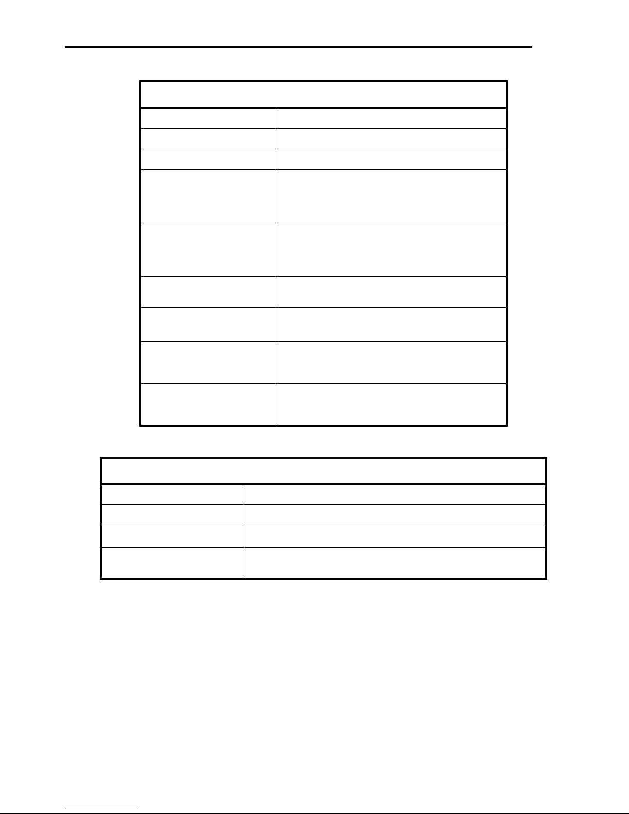
Digital audio formats supported by the FC726
Company/Organization Format Name Equipment Using Format Transmission Medium
Audio Engineering
Society
MADI Euphonix R-1, S-5; many large
format digital consoles
BNC cable
AES/EBU (AES-3) Most DAT machines and stereo
D/A devices, sound cards,
effects processors
Two balanced XLR
cables
Tascam TDIF-1 (Teac Digital
Interface Format)
Tascam DA-88, DA-98, small
format digital consoles and
workstations
25-pin cable
Mitsubishi ProDigi Otari and Mitsubishi digital
multitracks
Two 50-pin cables
Sony SDIF-2 Sony 3324 and 3348 Two 50-pin cables

FC726 Guide2
Basic Concepts
Channels and Banks
The FC726 can convert 56 digital audio channels in two direc-
tions simultaneously (simultaneous bidirectional conversion)
with any of the supported devices. The 56 channels are di-
vided into seven banks, each with eight channels. Each bank
may be connected to a different third-party device running at
a different sample rate (such as Tascam DA-88 on channels
1–8, ADAT on 9–16, and AES/EBU on 40–48).
Signal Flow
Since 56 channels can be converted bidirectionally, signal
routing can become confusing. These simple rules should help
clarify the signal flow:
• Audio arriving at the MADI B Input is sent out the
Format A Output.
• Audio arriving at the Format A connectors is sent out the
MADI B Output.
• The AES outputs always mirror the Format A Output.
Format A Inputs
Three connectors can be used by third-party inputs: the com-
mon DB-50 connectors, the MADI A Inputs, and the DB-25
AES connectors. The appropriate signal is chosen according to
the following rules:
• If the MADI switch is ON, the MADI input is used for all 56
channels.
• If the MADI switch is OFF, either the common DB-50 or AES
signals are used in eight-channel banks.
• If only one connector is in use, that format is selected.
• If both are connected, the common DB-50 signal takes
precedence.
Format A Adapters
To create a compact 2U device with maximum flexibility, the
FC726 uses a common DB-50 connector for all third-party for-
mats. An adapter is required to convert from the DB-50 con-
nector to the company’s own connector. The adapter is not
intended to be the connecting cable; it simply adapts the com-
mon DB-50 connector so it behaves like the back panel of the
third-party device. These adapters are available separately
from Avid. In most cases, another cable is required to connect
the adapter to the third-party device. See Appendix A, “Pinout
and Cable Specifications” for detailed information.
Sample Rate Conversion
Digital audio devices have previously been required to use the
same sample rate to operate correctly together. The FC726 re-
moves this limitation by allowing many sample rates simulta-
neously. For example, by using the common DB-50 connec-
tors, each eight-channel bank can operate at its own sample
rate. Furthermore, the FC726 detects different sample rates
and automatically activates Sample Rate Conversion (SRC).
Although the FC726 SRC is the highest quality available, some
users may still require an unaltered, bit-for-bit copy of the
data. In this case, connected devices can be slaved to the same
sample clock, which disables SRC automatically (you can also
disable SRC manually).

Chapter 1: Introduction to the FC726 3
System Requirements and
Compatibility
Avid can only assure compatibility and provide support for
hardware and software it has tested and approved.
For complete system requirements and a list of qualified
computers, operating systems, hard drives, and third-party
devices, visit www.avid.com/compatibility.
About This Guide
This guide provides a basic overview of FC726 features and
functionality.
For complete instructions on connecting and configuring
your system, see the System 5 Installation Guide.
Conventions Used in This Guide
All of our guides use the following conventions to indicate
menu choices and key commands:
:
The names of Commands, Options, and Settings that appear
on-screen are in a different font.
The following symbols are used to highlight important
information:
About www.avid.com
The Avid website (www.avid.com) is your best online source
for information to help you get the most out of your system.
The following are just a few of the services and features
available.
Product Registration Register your purchase online.
Support and Downloads Contact Avid Customer Success (tech-
nical support); download software updates and the latest on-
line manuals; browse the Compatibility documents for system
requirements; search the online Knowledge Base or join the
worldwide Avid user community on the User Conference.
Training and Education Study on your own using courses avail-
able online or find out how you can learn in a classroom set-
ting at a certified Avid training center.
Products and Developers Learn about Avid products; down-
load demo software or learn about our Development Partners
and their plug-ins, applications, and hardware.
News and Events Get the latest news from Avid or sign up for
a demo.
Convention Action
File > Save Choose Save from the File menu
Control+N Hold down the Control key and press
the N key
Control-click Hold down the Control key and click the
mouse button
Right-click Click with the right mouse button
User Tips are helpful hints for getting the most from
your system.
Important Notices include information that could affect
your data or the performance of your system.
Shortcuts show you useful keyboard or mouse shortcuts.
Cross References point to related sections in this guide and
other Avid guides.

FC726 Guide4
Chapter 2: FC726 Features 5
Chapter 2: FC726 Features
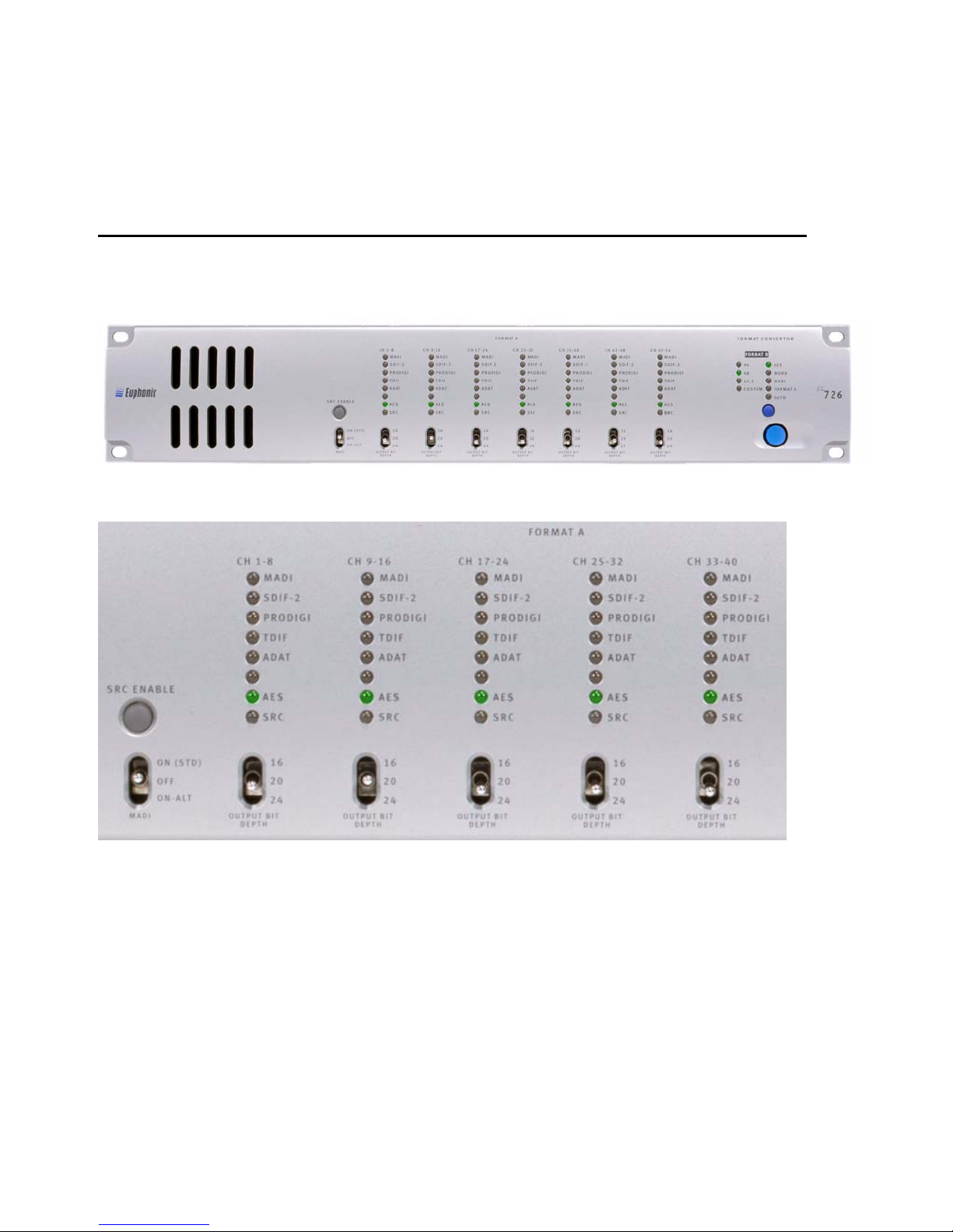
Front Panel
The FC726 front panel is shown below. Numbers in the subsequent figures correspond to the numbered items below.
1. MADI Switch
This three-position switch selects whether MADI is used for
the Format A Input and the characteristics of the MADI signal.
ON-STD Selects the standard MADI settings used by Avid
(sample rate = frame rate).
OFF Selects the common DB-50 connectors and ignores the
Format A MADI inputs. Use this setting with SDIF, TDIF,
ProDigi, ADAT, or AES devices.
ON-ALT Selects MADI running at sample rate = 96 kHz, frame
rate = 48 kHz.
2. SRC ENABLE Button
This button lights when the FC726 detects different sample
rates on the A and B formats and SRC is being used. Press the
button when lit to turn off SRC. The button flashes if SRC is
needed but has been disabled by the user. Press the button
again to reset the automatic SRC detection circuitry.
When a device first locks to the FC726, the button may occa-
sionally light to indicate SRC is necessary when it is not. Press
the button twice to reset the FC726 automatic SRC detection
circuitry. SRC is not needed if the button does not light.
FC726 Front Panel
FC726 front panel (center detail)
444 44
1
233333
FC726 Guide6
3. FORMAT A Input Indicator LEDs
Each eight-channel bank has seven LEDs to indicate the for-
mat attached to the Format A Input; only one of these LEDs
can be lit at a time. The LED lights dimly yellow if an adapter
is attached but the FC726 has not locked; the LED lights bright
yellow when the FC726 locks to the device.
The bottom SRC LED functions independently of the first
seven. It lights red if the FC726 has detected that SRC is re-
quired on that bank; it flashes red if SRC is required but has
been disabled by the user.
4. OUTPUT BIT DEPTH Select Switch
For each eight-channel bank, this switch sets the bit depth for
the signal output to the Format A device. When set to 24, all
24 bits are transferred from the MADI input to the Format A
output device without dithering. When set to 20 or 16, the sig-
nal is dithered to the selected number of bits before being out-
put to the Format A device.
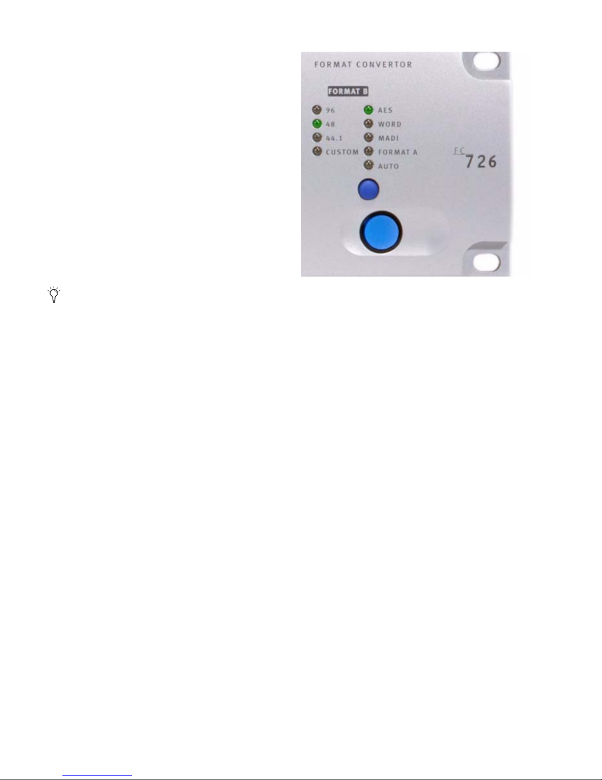
5. FORMAT B Sample Rate LEDs
These LEDs indicate the Format B sample rate. If the rate is not
44.1, 48, or 96 kHz (±3%), the CUSTOM LED lights. Since the
FC726 supports SRC, Format A may operate at several sample
rates that are not indicated by individual LEDs.
6. FORMAT B Sync Source LEDs
These LEDs show the Format B sync source. The blue button
below the AUTO LED manually cycles the sync source sequen-
tially from AUTO to AES, WORD, MADI, and FORMAT A.
When set to AUTO, the FC726 accepts the first sync signal de-
tected with the following priority: AES, WORD, MADI, and
FORMAT A. For example, if MADI and Format A sync are both
present, the selected source will be MADI because it is higher
in the priority list.
7. Power Switch
This switch turns power to the FC726 on or off.
This switch affects the Format A output only; it has
no effect on the Format B MADI audio output.
FC726 front panel (right detal)
65
7
Chapter 2: FC726 Features 7
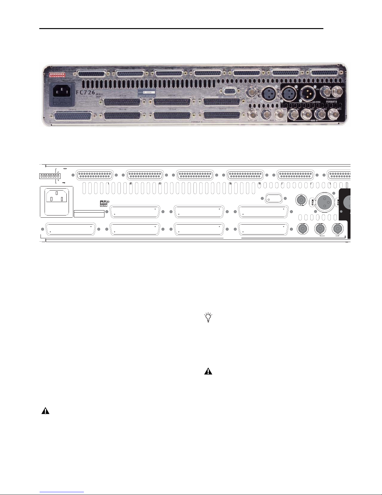
Back Panel
The FC726 back panel is shown below. Numbers in the subsequent figures correspond to the numbered items below.
1. AC Power Input
Connect the power cable shipped with the FC726 to its AC
input and an AC mains power source.
2. Format A Common DB-50 Connectors
Seven common DB-50 connectors connect third-party devices
to the FC726. Each connector provides eight bidirectional au-
dio channels. You must use the appropriate adapters for each
format to connect the third-party devices. See “Format A
Adapters” on page 2.
3. Format A AES Connectors
Seven DB-25 connectors connect AES devices to the FC726.
Each connector provides eight bidirectional channels (four
AES pairs). To connect to the third-party devices, use a
DB-25-to-XLR breakout cable available from Avid.
4. Format A MADI IN and MADI OUT
The Format A MADI In and MADI Out BNC connectors inter-
face with non-Avid MADI devices. At 48 kHz, MADI A pro-
vides 24-bit audio on 56 channels. At 96 kHz, only 28 24-bit
audio channels (1–28) are available.
5. Service DB-9 Jack
This jack connects to a PC serial port to upgrade the FC726
firmware.
FC726 Back Panel
FC726 back panel (left detail)
FC726
EUPHONIX, INC.
PALO ALTO
MADE IN THE U.S.A.
AES 49-56 AES 41-48 AES 33-40 AES 25-32 AES 17-24 AES 9-1
SERVICE IN IN
AES
SYNC
MADI A
IN
CH 49-56 CH 41-48 CH 33-40 CH 25-32
CH 17-24 CH 9-16 CH 1-8
SDIF-2 SYNC
or
SLAVE CLK
OUT
FORMAT A
OUT
VAC FUSE
100-240 1.0-0.5A 2.5A
50/60Hz SLOW
CURRENT
FMT A FMT B
AES STEREO
AES MONO
FMT A AES/FMT B/FMT A
SLAVE CLK
333336 3
1
2222
22 2
587
94
Do not use DB-25-to-XLR breakout cables made by
other companies because the pin numbering may be
incompatible. See Appendix A, “Pinout and Cable
Specifications” for specific cable information.
Unlike MADI B, which has a second set of I/O connec-
tors, MADI A provides only 28 channels at 96 kHz.
Do not connect anything to the Service DB-9 jack unless
instructed to do so by Avid technical support.

FC726 Guide8
6. DIP Switches
These eight DIP switches (numbered 1–8 from left to right) set
various modes on the FC726. Switches 3–5 and 7 are not cur-
rently implemented.
Switch #1 Bidirectional mode
Flip this switch when converting between third-party formats
using one FC726.
Switch #2 MADI MERGE
When set to MADI MERGE (down), Format B MADI Input 1
channels 1–24 are merged with Format B MADI Input 2 chan-
nels 1–28 and Format B MADI Input 1 channels 25–28 to form
a single 56-channel input stream. Format B MADI Output 1
sends channels 1–56 and Format B MADI Output 2 sends
channels 25–56 followed by 1–24 from the third-party inputs.
Switch #6 AES MASTER/SLAVE
When set to SLAVE (up), the Format A AES outputs lock to
their corresponding AES inputs. Within each bank, all AES
outputs operate at the sample rate of the lowest-numbered,
locked AES input. For example, if the first bank (channels 1–8)
has a 44.1 kHz AES signal connected to inputs 1–2 and a 48
kHz input connected to inputs 5–6, then AES output channels
1–8 will all run at 44.1 kHz. If AES inputs are not present on a
bank, Format A will get sample clock from the Format B Sync
input. If sync is not present, Format A will then lock to the
Format B Sync Input.
When set to MASTER (down), Format A AES outputs get sam-
ple clock from the Format A Sync input. If Format A sync is
not present, the Format A AES outputs will then lock to the
Format B Sync Input.
Switch #8 AES STEREO/AES MONO
Set this switch to AES Stereo (up) for the normal configuration
where each AES signal contains two discreet channels. If the
sample rate is above 52 kHz (such as 88.2 or 96 kHz), and the
AES signal connected to the FC726 implements two-wire AES
(also referred to as mono mode AES), set the switch to AES
Mono (down). This setting treats each AES signal as a single
channel with a frame rate running at half its sample rate. For
example, a 96 kHz two-wire AES signal runs at 48 kHz by using
the left channel for the even samples and the right channel for
the odd samples. This switch affects both the AES inputs and
outputs.
7. Format A AES Sync In
Connect an AES sync signal to this XLR connector to synchro-
nize the Format A MADI signal. According to the AES specifi-
cation, the AES sync signal must use the same sample rate as
the incoming MADI signal to operate correctly.
8. SDIF-2 or SLAVE CLK IN
This connector can receive either an SDIF or slave clock sync
signal. The FC726 automatically detects which signal type has
been connected.
An SDIF device must send a word sync signal to this connector
to properly connect to the FC726.
9. SLAVE CLK OUT
If Slave Clk In has a valid sync signal, it is passed through to
Slave Clk Out. If Slave Clk In does not have a valid sync signal,
the lowest numbered bank that is locked and in use is selected
as the clock source.
It is possible, but not recommended, to connect a
MADI signal without using a corresponding sync
signal. Providing an AES or Word sync results in
lower jitter and should be used whenever possible.
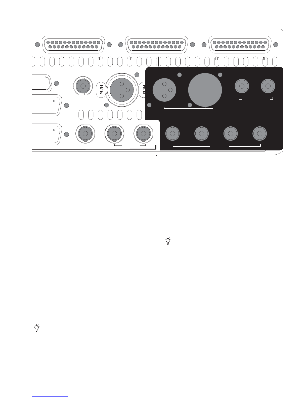
Chapter 2: FC726 Features 9
10. Format B MADI IN 1 and MADI OUT 1
These BNC connectors are used to interface with a MADI de-
vice. (such as a Studio Hub, MA703, or AM713) At 48 kHz, the
Format B MADI In 1 and MADI Out1 connectors provide 56
24-bit audio channels. At 96 kHz, they provide 28 24-bit audio
channels (channels 1–28).
11. Format B MADI IN 2 and MADI OUT 2
At 96 kHz, the Format B MADI In 2and Out 2 connectors pro-
vide 28 additional 24-bit audio channels (29–56).
At 48 kHz, Format B MADI In 2 is ignored and Format B MADI
Out 2 carries the same audio as Format B MADI Out 1 but with
the channel numbering reversed: Format A channels 29–56
are output on Format B MADI Out 2 channels 1–28; Format A
channels 1–28 are output on Format B MADI Out 2 channels
29–56.
12. Format B AES SYNC IN
Connect an AES sync signal to this XLR connector to synchro-
nize the Format B MADI signal. According to the AES specifi-
cation, the AES sync signal must use the same sample rate as
the incoming MADI signal to operate correctly.
13. Format B AES SYNC THRU
This connector outputs a copy of the Format B AES Sync In
signal.
14. Format B WORD SYNC IN
Connect a word sync signal to this BNC connector to synchro-
nize the Format B MADI signal. According to the AES specifi-
cation, the word sync signal must use the same sample rate as
the incoming MADI signal to operate correctly.
15. Format B WORD SYNC OUT
This connector outputs a copy of the Format B Word Sync In
signal. However, this output generates a word sync signal at
the Format B sample rate even if nothing is connected to For-
mat B Word Sync In. Note this important difference in behav-
ior from Format B AES Sync Thru.
FC726 Back Panel (detail)
AES 17-24 AES 9-16 AES 1-8
SERVICE
IN IN
AES
SYNC AES SYNC
WORD SYNC
IN OUT
FORMAT B
MADI A MADI B
IN 2 OUT 2
IN 1 OUT 1
IN
2
SDIF-2 SYNC
or
SLAVE CLK
OUT
OUT
IN THRU
SLAVE CLK
10 11
12 13 14 15
It is possible, but not recommended, to connect a
MADI signal without using a corresponding sync
signal. Providing an AES or Word sync results in
lower jitter and should be used whenever possible.
It is possible, but not recommended, to connect a
MADI signal without using a corresponding sync
signal. Providing an AES or Word sync results in
lower jitter and should be used whenever possible.

FC726 Guide10

Chapter 3: Operating Instructions 11
Chapter 3: Operating Instructions
This chapter provides instructions to connect devices
supported by the FC726.
SDIF-2
SDIF-2 is a 24-channel format with inputs and outputs on sep-
arate DB-50 connectors. The FC726 SDIF-2 adapter has three
DB-50 connectors, one for each eight-channel bank (labeled
1–8, 9–16, 17–24) but they may be connected to any FC726
bank. This allows routing the channels in eight-channel
groups.
The SDIF-2 format requires connecting an external word clock
on a BNC cable from the SDIF device to the FC726 SDIF-2 Sync
input or the FC726 will not lock. Turn the MADI switch on the
FC726 front panel to OFF (center position).
TDIF
1 Connect the TDIF adapter to the DB-50 connector(s) on the
FC726 back panel.
2 Turn the MADI switch on the FC726 front panel to OFF
(center position).
3 To avoid SRC, either lock the TDIF device to the MADI B de-
vice, or lock the MADI B device to the TDIF device:
• To lock the TDIF device to the MADI B device (i.e, System
5 or R-1), connect a word clock from the MADI device to
the TDIF device Word Sync In. The Format B Word Sync
Out on the FC726 may be used if no other word clock
output is available. Set the TDIF device to slave to its
word clock input.
• To lock the MADI B device to the TDIF device, connect
the TDIF device Word Sync Out to the MADI B device
word clock input. Set the MADI B device to slave to its
word clock input.
4 SRC is required if the MADI B device runs at 96 kHz and the
TDIF device at 48 kHz. The TDIF and MADI B devices can each
run on their own internal sample clocks without additional
sync signals.
ADAT
1 Connect the ADAT adapter to the DB-50 ports on the FC726
back panel.
2 Connect the ADAT optical cables to the ADAT back panel
and to the adapter’s optical input and output.
3 Turn the MADI switch on the FC726 front panel to OFF
(center position).
4 Set the ADAT adapter switch to the same setting used on the
ADAT front panel.
• If multiple slaved ADATs are connected, this switch
should match the setting of the first (master) ADAT. Al-
ways use the ADAT INT setting to perform SRC.
The switch on the ADAT adapter has two settings to tell the
FC726 how to synchronize to the ADAT optical device(s). Its
setting depends on whether the connected ADAT optical de-
vice slaves to the FC726 or runs on its own internal clock:
ADAT INT The ADAT runs on its own internal clock (INT refers
to internal).
ADAT DIG The ADAT slaves to its optical (digital) inputs (DIG
refers to digital). Since the optical input comes from the
FC726, this setting slaves the ADAT to the FC726.
ProDigi
ProDigi (PD) is a 16-channel format with inputs and outputs
on separate DB-50 connectors. The FC726 PD adapter has two
DB-50 connectors, one for each eight-channel bank (labeled
1–8 and 9–16). They may be connected to any bank on the
FC726 with one restriction: the connector labeled 1–8 must be
connected to a lower-numbered bank than the 9–16 connec-
tor. This allows the channels to be routed in eight-channel
groups. Turn the MADI switch on the FC726 front panel to
OFF (center position).

FC726 Guide12
AES
Each of the 28 AES inputs can run at a different sample rate.
The following rules clarify how the sample rate of the AES out-
put signal is derived:
• Within each bank, all AES outputs operate at the sample
rate of the lowest-numbered AES input that is locked. For
example, if the first bank (channels 1–8) has a 44.1 kHz
AES signal connected to inputs 1/2 and a 48 kHz input
connected to inputs 5/6, then AES output channels 1–8
all run at 44.1 kHz.
• If AES inputs are not present on a bank, but another For-
mat A device (i.e., TDIF) is connected and locked, the AES
outputs run at the Format A sample rate for that bank.
• If a bank has neither AES inputs nor a third-party device,
the AES outputs run at the Format B sample rate.
• If the MADI switch is On, the AES outputs run at the For-
mat A MADI sample rate.
Furthermore, these rules can be modified by DIP switch #6:
AES Master/Slave.
• If the switch is set to Master (up; the default position),
the rules stated above apply.
• If the switch is set to Slave (down), the AES outputs never
run at the AES input sample rate. Instead, they follow the
rules above assuming an AES input is not present. This
mode should be used to lock the connected AES device to
the AES output of the FC726.
Converting Between Formats
Using Two Units (56 Bidirectional Channels)
1 Connect Format B MADI Input of the first FC726 to the For-
mat B MADI Output of the second FC726.
2 Connect Format B MADI Input of the second FC726 to the
Format B MADI Output of the first FC726.
3 At 48 kHz, use the In1 and Out1 connectors; at 96 kHz, use
In1 and Out1 and In2 and Out2 connectors.
4 Connect the third-party devices as described in their sec-
tions of this chapter.
5 Connect a common sync source to both FC726s and all at-
tached third-party devices.
6 Do not allow both FC726s to attempt to lock to each other’s
MADI input.
Using One Unit (24 Bidirectional Channels)
1 Move DIP switch #1 to the down position.
2 Loop Format B MADI Out 2 to Format B MADI In 1.
3 If there is no sync on Format B, select Format A as the sync
source from the front panel.
4 Connect the third-party I/O devices.
The conversion is from third-party I/O channels 1–24 to chan-
nels 25–48. As always, all third-party inputs are still converted
to Format B MADI Out 1.
For example, to convert 24 channels of ADAT to 24 channels
TDIF (DA88), connect ADAT to third-party channels 1–24,
connect the three DA88s to channels 25–48 and follow the
steps above.
Chapter 3: Operating Instructions 13
Specifications
FC726 Performance Specifications
Sync Sources AES, word clock, MADI, Format A
Sync Outputs AES thru and word clock out
Sync Detection Auto or switched
Format A Audio Inputs
56 digital
AES (DB25), transformer isolated, 110
Third-Party I/O (DB50)
MADI (BNC), 75
Format A Audio Outputs
56 digital
AES (DB25), transformer isolated, 110
Third-Party I/O (DB50)
MADI (BNC), 75
Signal-to-Noise Ratio 144 dB (unweighted)
120 dB (unweighted) with SRC engaged
Group Delay SRC Off - 4 Fs
SRC On - 4 Fs+ ms delay (43/Fs input + 45/Fs output)
Format B MADI Inputs BNC 75
56 channels at 44.1/48 kHz
28 channels at 88.2/96 kHz
Format B MADI Output BNC 75
56 channels at 44.1/48 kHz
28 channels at 88.2/96 kHz
FC726 Technical Specifications
Power Requirements 110–240 VAC; 50 or 60 Hz (Auto-ranging)
Power Consumption 50 W
Temperature of Operation 5–35C
Dimensions Height: 3.5 in (89 mm); Width: 19 in (483 mm); Depth: 18.25 in (470 mm)
Weight: 13.5 lb (6 kg)

FC726 Guide14

Appendix A: Pinout and Cable Specifications 15
Appendix A: Pinout and Cable Specifications
This appendix provides detailed information about FC726 connectors for those who want to create or repair their own
cables. Contact Avid for a list of the adapters and cables available for third-party devices.
AES/EBU DB-25
The following figure shows the cable diagram, and the table shows the pinout for the FC726 AES/EBU DB-25 connector.
The ADAT requires an adapter that contains active electronics with a DB-50 connector on one end and an ADAT optical con-
nector on the other. This adapter cannot be constructed using the information presented in this appendix; contact Avid for this
adapter.
AESDB-25 breakout cable assembly diagram
PARTS LIST
Item Qty Euph P/N Mfr Mfr P/N Description
1 1 AMP HD-20 series DB25-M D-sub & shell
2 1 meter Mogami 3162 AES/EBU snake cable
Alternate: Belden 1805A AES/EBU snake cable
3 4 Neutrik NC3MX 3 p XLR M
4 4 Neutrik NC3FX 3 p XLR F
5 2 inch .75 OD shrink tubing
ITEM 5
Shrink tubing
ITEM 2
AES/EBU Snake
cable with 8
cores
Typical: 110 Ohm AES core, each
core individually shielded.
NOTE Tie each shield to pin 1 of
each destination XLR connector
ITEM 1
Db25 male
connector and metal
backshell assy with
thumbscrews or
jackscrews. J1
J2
J3
J4
J8
J7
J6
J5
ITEM 3
3-pin XLR
male connector
(4 places)
ITEM 4
3-pin XLR
Female (4 Places)
DB25
M
Approx. 1 meter
(38-40 inches)
AES/EBU
P/N 030-07658-01 REV B
Label cable with Euphonix
part number and Rev
letter as shown
Each XLR pigtail
destination label
(See Table 1 for
Nomenclature)
10 inches
each pigtail
TABLE 1 Cable Label Details
Conn. Label
DB25-M AES/EBU 030-07658-01 Rev
XLR-J1 1&2OUT
XLR-J2 3&4OUT
XLR-J3 5&6OUT
XLR-J4 7&8OUT
XLR-J5 1&2IN
XLR-J6 3&4IN
XLR-J7 5&6IN
XLR-J8 7&8IN

FC726 Guide16
Pin Description
Pin 1 N/C
Pin 2 Channel 1 / 2 In (COLD)
Pin 3 Channel 3 / 4 In (GND)
Pin 4 Channel 3 / 4 In (HOT)
Pin 5 Channel 5 / 6 In (COLD)
Pin 6 Channel 7 / 8 In (GND)
Pin 7 Channel 7 / 8 In (HOT)
Pin 8 Channel 1 / 2 Out (COLD)
Pin 9 Channel 3 / 4 Out (GND)
Pin 10 Channel 3 / 4 Out (HOT)
Pin 11 Channel 5 / 6 Out (COLD)
Pin 12 Channel 7 / 8 Out (GND)
Pin 13 Channel 7 / 8 Out (HOT)
Pin 14 Channel 1 / 2 In (GND)
Pin 15 Channel 1 / 2 In (HOT)
Pin 16 Channel 3/ 4 In (COLD)
Pin 17 Channel 5 / 6 In (GND)
Pin 18 Channel 5 / 6 In (HOT)
Pin 19 Channel 7 / 8 In (COLD)
Pin 20 Channel 1 / 2 Out (GND)
Pin 21 Channel 1 / 2 Out (HOT)
Pin 22 Channel 3 / 4 Out (COLD)
Pin 23 Channel 5 / 6 Out (GND)
Pin 24 Channel 5 / 6 Out (HOT)
Pin 25 Channel 7 / 8 Out (COLD)
In and Out are from the perspective of the FC726.
Table of contents
Other Avid Technology Media Converter manuals


