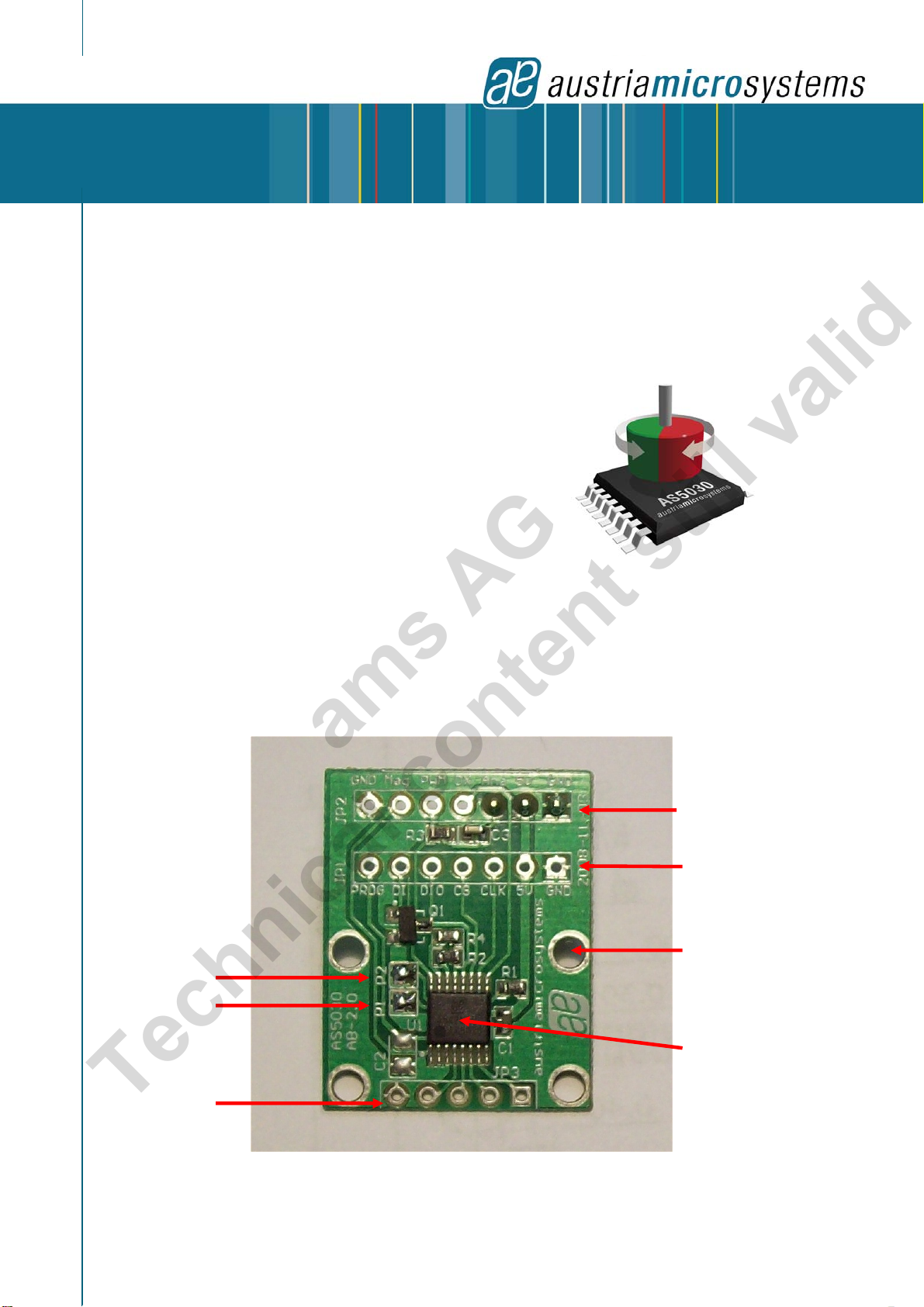
AS5030 8-bit Programmable Magnetic Rotary Encoder
Adapterboard Operation Manual
7C-Source code, simple AGC & Angle read
void main() // This program reads the angle and AGC value from AS5030
{
short SSI_Stream; // 16-bit value where the serial result will be saved
byte angle_value, agc_value; // 8-bit results: Angle and AGC
float angle_degree; // Angle in degree
SSI_Stream = SerialRead (0); // Send command “READ” (command ‘00000’)
// and reads the 16-bit result from AS5030
angle_value = (byte)(SSI_Stream & 0x00FF); // Extract the angle value (8 bit)
agc_value = (byte)((SSI_Stream >> 8) & 0x3F); // Extract the AGC value (6 bit)
angle_degree = (float)value * (360/256);// Convert the 8-bit angle to degrees (0-360°)
}
short SerialRead(unsigned char command) // This function writes the command
{ // and receives the result from the AS5030
short RX_buffer;
SET_CS(); // CS pin = ‘1’, AS5030 selected
delay_us(Delay_Serial);
SSIwrite(command); // Send the command (exemple “READ” command ‘00000’)
DIO_HIGH_IMP(); // DIO output high impedance (input mode), ready to read
RX_buffer = SSIread(); // Receive the 16bit result from the AS5030
delay_us(Delay_Serial);
CLEAR_CS(); // CS pin = ‘0’
return RX_buffer;
}
short void SSIread() // This function reads the 16-bit value from the AS5030 DIO pin
{
xdata unsigned char current_bit;
short result;
result = 0; // Is the shift buffer for the 16 bit data receive
for (current_bit = 16; current_bit; current_bit--) // 16 steps loop (16 bit data)
{
result <<= 1; // Shift buffer value left 1 step (first time doesn’t count)
delay_us(Delay_Serial); // Small delay to be get the correct level on DIO
result += (VAL_DIO) ? 1 : 0; // If ‘1’ on DIO, store ‘1’ on the LSB else ‘0’
SET_CLK(); // Generate a CLK pulse to shift the data on DIO
delay_us(Delay_Serial);
CLEAR_CLK();
}
return result;
}
void SSIwrite(unsigned char command) // This function writes the 5-bit command to
{ // the AS5030 DIO pin
unsigned char current_bit;
unsigned char this_bit
for (current_bit = 5; current_bit; current_bit--) // 5 steps loop (5 bit command)
{
this_bit = (command >> (current_bit-1)) & 0x01; // Value of bit 5, then
//
bit 4, …, bit 0
// If the current command bit is ‘1’:
if (this_bit) SET_DIO(); // then send ‘1’ on DIO (push-pull output)
else CLEAR_DIO(); // Otherwise send ‘0’ on DIO (push-pull output)
if (current_bit == 1) // If Last Bit has been written
{
delay_us(Delay_Serial);
SET_CLK(); // Set Clock
delay_us(Delay_Serial);
DIO_HIGH_IMP(); // And DIO output of CPU in input mode
delay_us(Delay_Serial);
CLEAR_CLK(); // Clear Clock (datasheet timings)
}
else // Else generate a CLK pulse to shift the data on DIO
{
delay_us(Delay_Serial);
SET_CLK();
delay_us(Delay_Serial);
CLEAR_CLK();
}
}
}
Revision 1.0, 26.February 2009
www.austriamicrosystems.com
Page 8 of 10
ams AG
Technical content still valid