Avid Technology Pro Tools MTRX User manual

PRO TOOLS | MTRX Operation Guide

Legal Notices
© 2021 Avid Technology, Inc., (“Avid”), all rights reserved. This guide may not be duplicated in whole or in part without the written consent of Avid.
For a current and complete list of Avid trademarks visit: www.avid.com/legal/trademarks-and-other-notices.
Bonjour, the Bonjour logo, and the Bonjour symbol are trademarks of Apple Computer, Inc.
Thunderbolt and the Thunderbolt logo are trademarks of Intel Corporation in the U.S. and/or other countries.
This product may be protected by one or more U.S. and non-U.S. patents. Details are available at www.avid.com/patents.
Product features, specifications, system requirements, and availability are subject to change without notice.
Guide Part Number 9329-66264-00 REV A 04/21

Pro Tools | MTRX Operation Guide iii
Chapter 1. Introduction. . . . . . . . . . . . . . . . . . . . . . . . . . . . . . . . . . . . . . . . . . . . . . . . . . . . . . . . . . . . . . . . . . . . . . . . . . . . 1
Pro Tools | MTRX AD/DA Converter . . . . . . . . . . . . . . . . . . . . . . . . . . . . . . . . . . . . . . . . . . . . . . . . . . . . . . . . . . . . . 1
Pro Tools | MTRX Overview . . . . . . . . . . . . . . . . . . . . . . . . . . . . . . . . . . . . . . . . . . . . . . . . . . . . . . . . . . . . . . . . . . . . 1
System Requirements and Compatibility Information . . . . . . . . . . . . . . . . . . . . . . . . . . . . . . . . . . . . . . . . . . . . . . . 4
/Conventions Used in Pro Tools Documentation . . . . . . . . . . . . . . . . . . . . . . . . . . . . . . . . . . . . . . . . . . . . . . . . . . . 4
Resources. . . . . . . . . . . . . . . . . . . . . . . . . . . . . . . . . . . . . . . . . . . . . . . . . . . . . . . . . . . . . . . . . . . . . . . . . . . . . . . . . . 5
Chapter 2. Pro Tools | MTRX Operation . . . . . . . . . . . . . . . . . . . . . . . . . . . . . . . . . . . . . . . . . . . . . . . . . . . . . . . . . . . . . 6
Pro Tools | MTRX Front Panel . . . . . . . . . . . . . . . . . . . . . . . . . . . . . . . . . . . . . . . . . . . . . . . . . . . . . . . . . . . . . . . . . . 6
Chapter 3. DADman Software . . . . . . . . . . . . . . . . . . . . . . . . . . . . . . . . . . . . . . . . . . . . . . . . . . . . . . . . . . . . . . . . . . . . . . 9
Assigning the IP Address for your Computer and MTRX. . . . . . . . . . . . . . . . . . . . . . . . . . . . . . . . . . . . . . . . . . . . . 9
DADman Menus . . . . . . . . . . . . . . . . . . . . . . . . . . . . . . . . . . . . . . . . . . . . . . . . . . . . . . . . . . . . . . . . . . . . . . . . . . . . 11
DADman Windows . . . . . . . . . . . . . . . . . . . . . . . . . . . . . . . . . . . . . . . . . . . . . . . . . . . . . . . . . . . . . . . . . . . . . . . . . . 12
Updating Pro Tools | MTRX Firmware . . . . . . . . . . . . . . . . . . . . . . . . . . . . . . . . . . . . . . . . . . . . . . . . . . . . . . . . . . . 18
Chapter 4. Network Fundamentals . . . . . . . . . . . . . . . . . . . . . . . . . . . . . . . . . . . . . . . . . . . . . . . . . . . . . . . . . . . . . . . . 19
What is a network?. . . . . . . . . . . . . . . . . . . . . . . . . . . . . . . . . . . . . . . . . . . . . . . . . . . . . . . . . . . . . . . . . . . . . . . . . . 19
Infrastructure . . . . . . . . . . . . . . . . . . . . . . . . . . . . . . . . . . . . . . . . . . . . . . . . . . . . . . . . . . . . . . . . . . . . . . . . . . . . . . 20
Addressing . . . . . . . . . . . . . . . . . . . . . . . . . . . . . . . . . . . . . . . . . . . . . . . . . . . . . . . . . . . . . . . . . . . . . . . . . . . . . . . . 20
Chapter 5. Pro Tools | MTRX Back Panel Connections . . . . . . . . . . . . . . . . . . . . . . . . . . . . . . . . . . . . . . . . . . . . . . 22
Digital I/O Connections . . . . . . . . . . . . . . . . . . . . . . . . . . . . . . . . . . . . . . . . . . . . . . . . . . . . . . . . . . . . . . . . . . . . . . 23
Analog I/O Connections . . . . . . . . . . . . . . . . . . . . . . . . . . . . . . . . . . . . . . . . . . . . . . . . . . . . . . . . . . . . . . . . . . . . . . 25
Example System Configurations . . . . . . . . . . . . . . . . . . . . . . . . . . . . . . . . . . . . . . . . . . . . . . . . . . . . . . . . . . . . . . . 26
Appendix A. Specifications. . . . . . . . . . . . . . . . . . . . . . . . . . . . . . . . . . . . . . . . . . . . . . . . . . . . . . . . . . . . . . . . . . . . . . . . . . 27
Audio Specifications . . . . . . . . . . . . . . . . . . . . . . . . . . . . . . . . . . . . . . . . . . . . . . . . . . . . . . . . . . . . . . . . . . . . . . . . 27
Electrical Specifications . . . . . . . . . . . . . . . . . . . . . . . . . . . . . . . . . . . . . . . . . . . . . . . . . . . . . . . . . . . . . . . . . . . . . 28
Mechanical Specifications . . . . . . . . . . . . . . . . . . . . . . . . . . . . . . . . . . . . . . . . . . . . . . . . . . . . . . . . . . . . . . . . . . . . 29
Environmental Specifications . . . . . . . . . . . . . . . . . . . . . . . . . . . . . . . . . . . . . . . . . . . . . . . . . . . . . . . . . . . . . . . . . 29
Appendix B. Controlling MTRX Preamps from Pro Tools (Mac Only) . . . . . . . . . . . . . . . . . . . . . . . . . . . . . . . . . . . . . . . 30
Configuring Audio MIDI Setup . . . . . . . . . . . . . . . . . . . . . . . . . . . . . . . . . . . . . . . . . . . . . . . . . . . . . . . . . . . . . . . . . 30
Configure DADman . . . . . . . . . . . . . . . . . . . . . . . . . . . . . . . . . . . . . . . . . . . . . . . . . . . . . . . . . . . . . . . . . . . . . . . . . 30
Configure Pro Tools Software . . . . . . . . . . . . . . . . . . . . . . . . . . . . . . . . . . . . . . . . . . . . . . . . . . . . . . . . . . . . . . . . . 31
Controlling MTRX from Pro Tools (or from a Control Surface) . . . . . . . . . . . . . . . . . . . . . . . . . . . . . . . . . . . . . . . 32
Contents

Pro Tools | MTRX Operation Guide
iv
Appendix C. Monitoring with MTRX and S6. . . . . . . . . . . . . . . . . . . . . . . . . . . . . . . . . . . . . . . . . . . . . . . . . . . . . . . . . . . . . 33
Creating a Monitor Profile for Pro Tools | MTRX in DADman Software . . . . . . . . . . . . . . . . . . . . . . . . . . . . . . . . . 33
Assigning Monitor Sources on S6 . . . . . . . . . . . . . . . . . . . . . . . . . . . . . . . . . . . . . . . . . . . . . . . . . . . . . . . . . . . . . . 42
Appendix D. SPQ Expansion Card Operation . . . . . . . . . . . . . . . . . . . . . . . . . . . . . . . . . . . . . . . . . . . . . . . . . . . . . . . . . . . 45
SPQ Overview . . . . . . . . . . . . . . . . . . . . . . . . . . . . . . . . . . . . . . . . . . . . . . . . . . . . . . . . . . . . . . . . . . . . . . . . . . . . . . 45
Inspecting the SPQ Card and Firmware Versions. . . . . . . . . . . . . . . . . . . . . . . . . . . . . . . . . . . . . . . . . . . . . . . . . . 46
DADman and Monitoring . . . . . . . . . . . . . . . . . . . . . . . . . . . . . . . . . . . . . . . . . . . . . . . . . . . . . . . . . . . . . . . . . . . . . 47
General Delay . . . . . . . . . . . . . . . . . . . . . . . . . . . . . . . . . . . . . . . . . . . . . . . . . . . . . . . . . . . . . . . . . . . . . . . . . . . . . . 48
EQ . . . . . . . . . . . . . . . . . . . . . . . . . . . . . . . . . . . . . . . . . . . . . . . . . . . . . . . . . . . . . . . . . . . . . . . . . . . . . . . . . . . . . . . 49
Configuring Bass Management . . . . . . . . . . . . . . . . . . . . . . . . . . . . . . . . . . . . . . . . . . . . . . . . . . . . . . . . . . . . . . . . 52
Configuring Custom Speaker and Source Formats . . . . . . . . . . . . . . . . . . . . . . . . . . . . . . . . . . . . . . . . . . . . . . . . 54
Fold-down and Speaker Match. . . . . . . . . . . . . . . . . . . . . . . . . . . . . . . . . . . . . . . . . . . . . . . . . . . . . . . . . . . . . . . . . 55
Saving and Loading Monitor Profile Settings . . . . . . . . . . . . . . . . . . . . . . . . . . . . . . . . . . . . . . . . . . . . . . . . . . . . . 56
Group Format . . . . . . . . . . . . . . . . . . . . . . . . . . . . . . . . . . . . . . . . . . . . . . . . . . . . . . . . . . . . . . . . . . . . . . . . . . . . . . 57
Appendix E. I/O Delays . . . . . . . . . . . . . . . . . . . . . . . . . . . . . . . . . . . . . . . . . . . . . . . . . . . . . . . . . . . . . . . . . . . . . . . . . . . . . 58
MTRX Input to Output Delays. . . . . . . . . . . . . . . . . . . . . . . . . . . . . . . . . . . . . . . . . . . . . . . . . . . . . . . . . . . . . . . . . . 58
Chapter 1: Introduction 1
Chapter 1: Introduction
Pro Tools | MTRX AD/DA Converter
Welcome to Pro Tools | MTRX™for Pro Tools | Ultimate™software running with Pro Tools | HDX™or Pro Tools | HD™Native
hardware. MTRX is a versatile, expandable, multi-channel audio converter and microphone preamplifier for independent simulta-
neous analog-to-digital (A/D) and digital-to-analog (D/A) conversion as well as digital-to-digital (D/D) format conversion and sig-
nal routing.
In its factory configuration, MTRX provides built-in AES/EBU inputs and outputs (for up to 16 channels of I/O), two DigiLink™
Mini ports for up to 64 input and output channels with Pro Tools | HDX or HD Native hardware, and coaxial MADI input and out-
put connections for up to 64 channels of MADI I/O.
MTRX provides eight expansion card slots for analog and digital I/O, and for SPQ processing. MTRX can be fitted with up to six
analog I/O expansion cards, providing up to 48 channels of analog I/O. MTRX can host up to eight digital I/O expansion cards sup-
porting different digital formats, such as MADI, Dante®, AES/EBU, DigiLink, and SDI. MTRX also provides a mini-module slot
for an optional MTRX Dual MADI I/O module. Additionally, an optional MTRX 64-Channel IP Audio Dante module can be in-
stalled on the MTRX motherboard. You can install one or more optional DigiLink expansion cards for up to 576 channels of
DigiLink I/O with a single MTRX (each DigiLink card provides up to 64 channels of DigiLink I/O in addition to the built in
DigiLink ports).
Pro Tools | MTRX Overview
Pro Tools | MTRX features:
• 64-channel audio interface for Pro Tools with two DigiLink Mini ports (Primary and Primary/Expansion).
• Built-in AES/EBU DB-25 connections for up to 16 channels of digital I/O.
• Built-in MADI coaxial connections for up to 64 channels of digital I/O.
• Ethernet IP audio interface for 64 I/O channels using Dante with configurable redundant network (with either the optional Dante
Expansion card or the Dante module installed).
• Digital router and format converter between all analog and digital inputs and outputs.
• Sample rates of 44.1–384 kHz as well as DSD64/DSD 128 with high precision internal clock and PLL.
• Sample rate can be adapted to the setting of an external device.
• Synchronization by Word Clock, AES11, Video, and all digital audio inputs.
• All settings are controlled over Ethernet using DADman software (macOS or Windows).
• Some settings can be controlled on the front panel.
• Ultra low-noise internal fan with speed adaptation to the temperature.
This guide provides basic information about using Pro Tools | MTRX and DADman software. For installation instructions, includ-
ing information on installing expansion cards, the MADI mini-module, and the Dante module, see the printed Pro Tools | MTRX
Installation Guide that came with your unit or download the latest PDF version of the guide from your Avid Master Account.

Chapter 1: Introduction
2
Pro Tools | MTRX lets you install optional I/O expansion cards in any of the eight back panel slots that include:
• Up to 48 analog channels depending on the configuration of installed Analog I/O Expansion Cards (up to 6 cards):
• Pro Tools | MTRX 8 Line Pristine AD Card provides eight channels of line-level analog inputs.
• Pro Tools | MTRX 2 Mic/Line Pristine AD Card provides two channels of analog inputs and mic preamps with relay-based gain
circuit—an ideal low-cost option for talk-back and tracking—includes microphone preamplifiers with relay-based gain circuits.
• Pro Tools | MTRX 8 Mic/Line Pristine AD Card provides eight channels of analog inputs and mic preamps with relay-based gain
circuits.
• Pro Tools | MTRX Pristine 8 DA Card provides eight channels of line-level analog outputs with an output level control.
• Digital I/O Expansion Cards (up to 6 cards):
• Pro Tools | MTRX 8 AES3 I/O Card provides eight line AES3 inputs and outputs (16 channels) with built-in sample rate conver-
sion.
• Pro Tools | MTRX Dual SDI/HD/3G Card provides 2 x 16 channels of SDI/HD/3G connections with built-in sample rate conver-
sion.
• Pro Tools | MTRX Dual MADI I/O Card provides up to 128 channels of MADI inputs and outputs through two optical SFP ports,
and also provides SRC on input.
• Pro Tools | MTRX MADI mini-module for the Base Unit provides additional one or two 64-channel I/O coaxial or optical MADI
module to the chassis.
• Pro Tools | MTRX Dante 128 Card provides up to 128 channels of high-density, low-latency digital audio using Dante (128 chan-
nels at 44.1 kHz or 32 channels at 192 kHz), and also provides Sample Rate Conversion (SRC).
• Pro Tools | MTRX 64-Channel IP Audio Dante module can be installed on the motherboard and provides up to 64 channels of
low-latency digital audio using Dante (64 channels at 44.1 kHz or 16 channels at 192 kHz).
• DigiLink Expansion Card:
• Pro Tools | MTRX DigiLink Card provides 2 DigiLink ports to connect to HDX cards, HD Native, or additional audio interfaces
(such as HD MADI I/O) for up to 64 channels of DigiLink I/O per card.
• DSP/FPGA Card:
• Pro Tools | MTRX SPQ Speaker Processor Card provides monitor control, speaker matching, delay controls, and comprehensive
EQ and bass management in all output formats. It supports up to 128 channels at 48 kHz with up to 16 EQ filters per channel.
Clock and Synchronization System
The MTRX clock system supports various internal and external clock modes. MTRX has a precise and very high quality internal sample
clock generator, which can also be clocked from an external clock signal by means of a very accurate Digital Phase Locked Loop
(DPLL) system.
The MTRX clock system has to be set to the correct sample rate with which the units should operate. This is the case both when oper-
ating with the internal sample clock generator as master clock, or when synchronized to an external clock source. The sample rates sup-
ported are based on either 44.1 or 48 kHz sampling. An external clock must always have a correct base rate in relation to the sample rate
used.
The sample rate with which the MTRX should operate can be set manually using DADman software or using the controls on the front
panel. You can also set the sample rate from Pro Tools. When using the IP Audio interface powered by Dante, the sample rate of the
Dante I/O node to the IP Audio network can be set to follow the sample rate of the MTRX. When multiple MTRX units are operating
in the same set up or IP Audio network, they must all be set to the same sample rate.
MTRX is compliant with the Dante Controller and Dante Virtual Sound Card, and also supports Dante Domain Manager.
For information on how to configure the synchronization and sample rates, see Pro Tools | MTRX Operation.
Chapter 1: Introduction
3
Routing Matrix
Pro Tools | MTRX provides a powerful routing matrix. All input signals can be patched to one or more outputs on a mono-channel basis,
so MTRX is also a digital patch bay. Configure MTRX routing using DADman software.
In order to set up the correct signal flow in MTRX, the correct connections have to be set in the matrix using DADman software. Any
of the analog or digital inputs installed in the MTRX can be patched to any analog or digital output, or can be routed to multiple outputs.
For example, with sixteen analog input channels, each one can be routed to Pro Tools and from Pro Tools to a MADI output. At the same
time, another two channels from Pro Tools can be routed to stereo analog outputs on MTRX. Additionally, each of the AES/EBU input
channels can be routed to matching optical MADI outputs.
It is essential that all digital signals connected to the MTRX are synchronized to the same master clock.
In order to patch IP Audio channels between different devices, use the Dante Controller software tool from Audinate.
*
MTRX sample clock circuit
For details on how to configure the routing matrix, see Pro Tools | MTRX Operation.
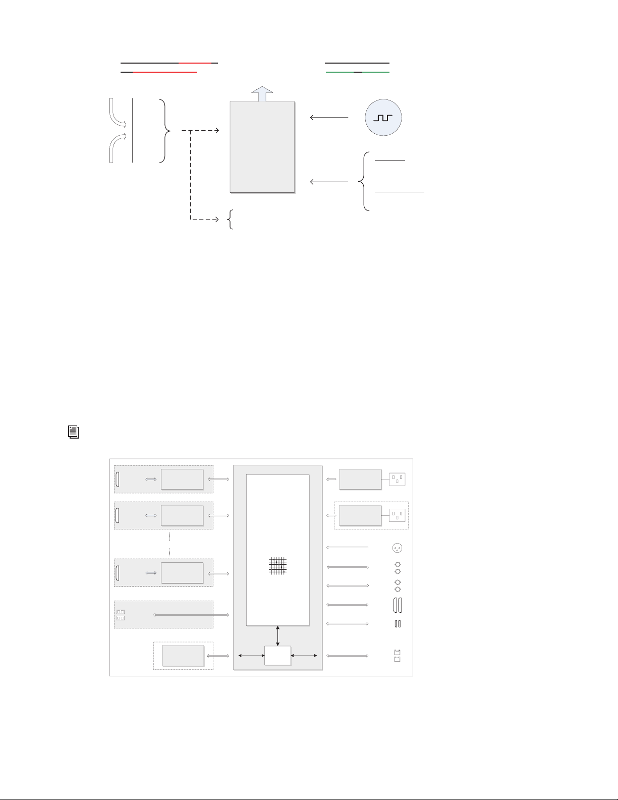
MTRX block diagram
Ext. Clock
sync sources
Clock generator
DPLL
Word Clock
AES11
Clock input
Digital signal input
MADI 1-3
AES3 1-8
IP Audio
Int. Clock
44,1
48
88,2
96
174,4
192
352,8
384
DSD
Manual Sample
Rate selection
Sample rate
adapt to:
Pro Tools
MADI
AES3
Sample Rate
Control
Follow
No follow
IP Audio
Sample Rate set manually or
via external adaptation
Sample Rate set to
Internal or external
Internal
sample clock
AD/mic pre or
DA Mains 1
2xD25
Connectors
2xBNC
Connectors
2xSDR-mini
Connectors
2xRJ45
Connectors
1xD25
Connector
0 to 6 x I/O Modules AES11
Sync input
WC/VBB in
WC sync out
2xBNC
Connectors
1xXLR
Connector
1xMADI,
64 ch. I/O
8xAES3,
16 ch I/O
2xDigiLink,
16/64 ch. I/O
2xGB Ethernet
Control and 64
ch. IP Audio I/O
8 ch. Analogue
in or out
AD/mic pre or
DA
1xD25
Connector
8 ch. Analogue
in or out
AD/mic pre or
DA
1xD25
Connector
8 ch. Analogue
in or out
I/O Card
I/O Card
I/O Card
2xOptical
SFP Connector
2xMADI,
128 ch. I/O
Mini Module
Dante
Brooklyn II module
IP Audio option
FPGA based
router matrix,
DSP processor
and controller
Ethernet
GigaBit
Switch
PSU 1
PSU 2 Mains 2
Optional PSU
Main board
Chapter 1: Introduction
4
System Requirements and Compatibility Information
Pro Tools | MTRX is supported by a compatible version of Pro Tools | Ultimate software with Pro Tools | HDX or HD Native hardware.
Avid recommends using a grounded, switchable power supply with MTRX for powering the unit on and off.
For the latest Pro Tools | MTRX system requirements and resources, visit www.avid.com/products/pro-tools-mtrx.
For complete system requirements and a list of qualified computers, operating systems, storage solutions, peripherals, control surfaces,
and third-party devices, visit www.avid.com/compatibility.
Avid can only assure compatibility and provide support for hardware and software it has tested and approved.
/
Conventions Used in Pro Tools Documentation
Pro Tools documentation uses the following conventions to indicate menu choices, keyboard commands, and mouse commands:
:
The names of Commands, Options, and Settings that appear on-screen are in a different font.
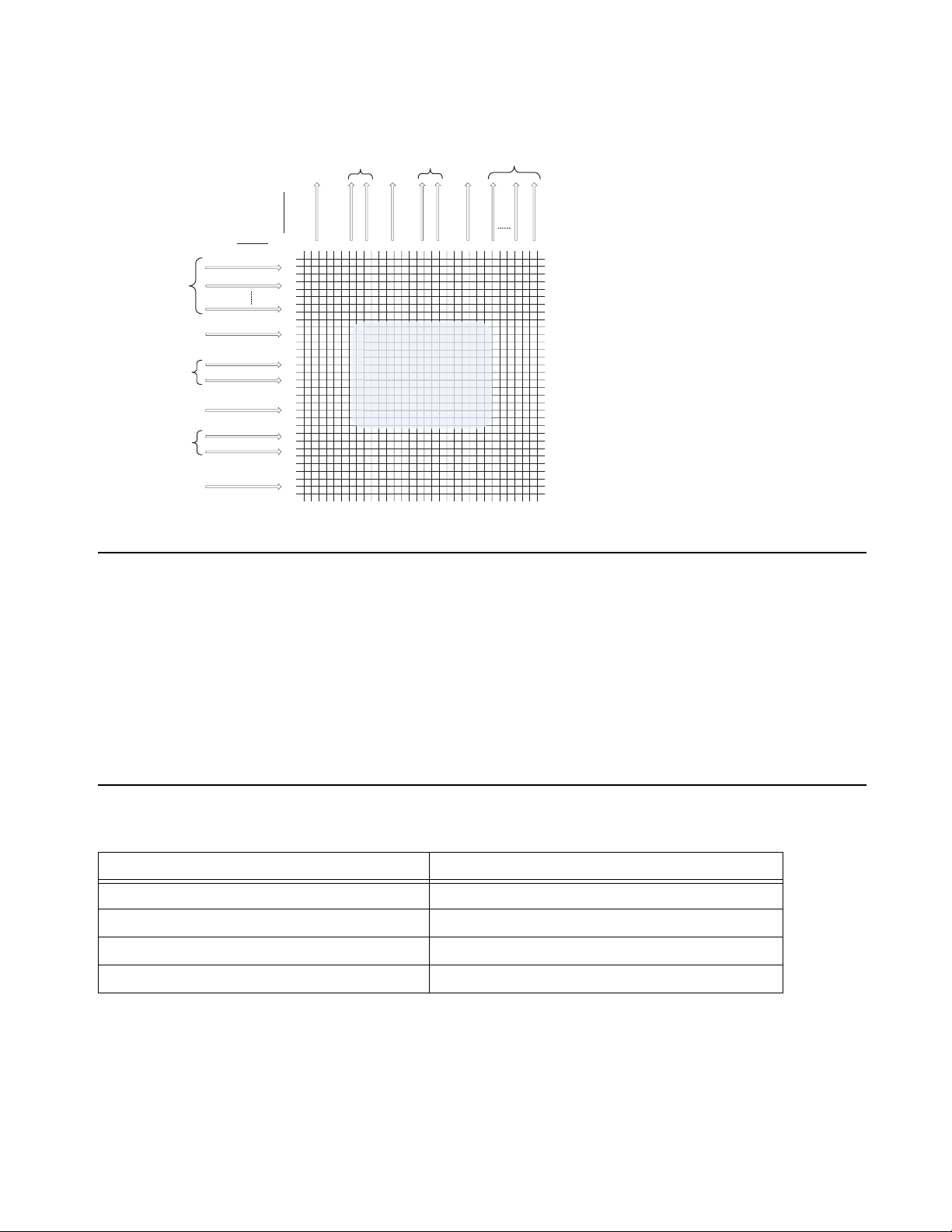
MTRX router matrix
Convention Action
File > Save Choose Save from the File menu
Control+N Hold down the Control key and press the N key
Control-click Hold down the Control key and click with the mouse
Right-click Click with the right mouse button
1 x MADI input
8 x AES3 input
2 x DigiLink inputs
IP Audio inputs
0 – 48 ch.
Analog inputs
2 x optical MADI
inputs
Ch. 1-8
Ch. 9-16
Ch. 41-48
Ch. 1-64
Ch. 1-64
Ch. 1-64
Ch. 1-16
Ch. 1-32
Ch. 1-32
Ch. 1-64
1x MADI output
8x AES3outputs
2x DigiLink
outputs
IP Audio outputs
0 – 4
8ch.
Analog outputs
2 x optical MADI
outputs
Ch. 1-8
Ch. 9-16
Ch. 41-48
Ch. 1-64
Ch. 1-64
Ch. 1-64
Ch.1-16
Ch.1-32
Ch. 1-32
Ch. 1-64
OUTPUTS
INPUTS
1500 x 1500
Router Matrix

Chapter 1: Introduction
5
The following symbols are used to highlight important information:
Resources
The Avid website (www.avid.com) is your best online source for information to help you get the most out of your Avid system.
Account Activation and Product Registration
Activate your product to access downloads in your Avid account (or quickly create an account if you do not have one). Register your
purchase online, download software, updates, documentation, and other resources.
www.avid.com/account
Support and Downloads
Contact Avid Customer Success (technical support), download software updates and the latest online manuals, browse compatibility
documents for system requirements, search the online Knowledge Base or join the worldwide Avid user community on the User Con-
ference.
www.avid.com/support
Training and Education
Study on your own using courses available online, find out how you can learn in a classroom setting at an Avid-certified training center,
or view video tutorials and webinars.
www.avid.com/education
Video Tutorials
The Get Started Fast with Pro Tools series of online videos provide tutorials to help if you are new to Pro Tools. They also provide vid-
eos for the experienced user that introduce new features found in the latest versions of Pro Tools.
www.avidblogs.com/get-started-fast-with-pro-tools/
The MTRX in Focus series of videos on YouTube provide tutorials specifically for Pro Tools | MTRX:
Products and Developers
Learn about Avid products, download demo software, or learn about our Development Partners and their plug-ins, applications, and
hardware.
www.avid.com/products
User Tips are helpful hints for getting the most from your Pro Tools system.
Important Notices include information that could affect your Pro Tools session data or the perfor-
mance of your ProToolssystem.
Shortcuts show you useful keyboard or mouse shortcuts.
Cross References point to related sections in this guide and other Avid documentation.

Chapter 2: Pro Tools | MTRX Operation 6
Chapter 2: Pro Tools | MTRX Operation
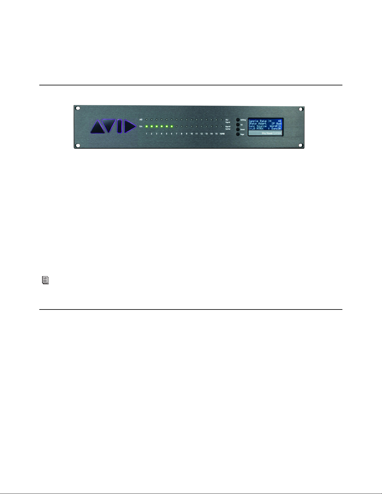
Pro Tools | MTRX is controlled over Ethernet by DADman software on your computer. Some controls are also available on the
front panel of the unit. Two rows of LED indicators show the AD and DA signal level, and an LCD display that shows various set-
tings of the MTRX. The four front panel buttons let you access the settings shown in the display.
Pro Tools | MTRX Front Panel
116 LED indicators indicating signal level of analog input.
216 LED indicators indicating signal level of analog output.
34 buttons for operating the status display.
4Status display.
Front Panel LEDs
MTRX has two rows of 16 LED indicators on the front panel showing the signal status for the AD inputs and DA outputs.
AD OL/Signal
Signal of AD channels 1–16. Yellow indicates signal input above –42 dB FS, and red indicates signal level above –
0.5 dB FS.
DA Signal/Carrier
Signal of DA channels 1–16. Yellow indicates signal input above –42 dB FS. Green indicates signal below –
42 dB FS and a valid digital input source/carrier.
Front Panel Status Display
The display of the MTRX has four rows for displaying information and four buttons for entering and scrolling information. The dis-
play can show more pages and each page can consist of rows where settings can be changed, and with rows for just showing status
information. The display functions for the basic page are described below. More pages are available depending on the firmware
version of the MTRX.
Pro Tools | MTRX front panel
1
2
34
AD
DA
Signal
OL /
Signal/
Carrier
1 2 15 16/48

Chapter 2: Pro Tools | MTRX Operation
7
Operating Buttons
Setting
Pushing the Setting button scrolls trough the settings rows. The > cursor marks the selected row/function.
Up
Pushing the Up button scrolls up the value/setting of the selected function.
Down
Pushing the Down button scrolls down the value/setting of the selected function.
Page
Pushing the Page button scrolls trough the available display pages.
Basic Display Page
(Sample Rate, Synchronization, ID, and Alarms)
Sample Rate
Shows the sample rate of the MTRX. If an asterisk * is shown, the sample rate is controlled by an external digital audio
interface.
SRate Adapt
Shows which external digital audio interface controls the sample rate, or it shows Intern for internal sample rate control.
Sync Source
Shows the external synchronization clock source, or shows Intern when the MTRX is using the internal clock.
Unit ID/Name
Shows the unit ID number and unit name. This is configured using DADman software.
Alarm/Status
Shows the alarm status indicating Clock Sync or an operational error.
Alarm/Status Display Description
Sync OK Clock sync is OK.
SyncErr Clock sync failure.
TempErr The temperature inside MTRX is above 60ºC/140ºF. Check that the MTRX is properly
installed to allow airflow.
Fan Err One of the two fans is not working correctly. Contact an Avid representative.
CardErr Fault in one of the A/D or D/A cards. Contact an Avid representative.
Psu Err Power supply failure. Contact an Avid representative.
Setting
Up
Down
Page
Pro Tools | MTRX
PT HD1
Sample Rate *
>
:
SRate Adapt
Sync Source
1:NameUnit
48
Intern
Sync OK

Chapter 2: Pro Tools | MTRX Operation
8
Reconfig Button
The Reconfig button on the back of the MTRX should not be used during normal installation. It is generally intended as an ultimate re-
covery function in case something goes wrong during programming of IP addresses, a software upgrade, or an unintended power loss.
It allows the MTRX to start in various “basic” modes so it can be restored without having to be returned to Avid.
The Reconfig button is accessed through a hole in the rear panel using a pen or a similar pointed item. A green Status LED is visible
through the hole. When the Reconfig button is activated, the LED lights up indicating the two reconfig modes of the MTRX.
Recovery Mode
To enter Recovery mode, push and hold the Reconfig button for approximately 10 seconds while powering up the unit. The Status LED
turns green. In this mode only a basic boot software is operative in the unit, and new software can be downloaded using DADman soft-
ware. This mode is used if the software in the MTRX is not operational or is otherwise malfunctioning.
The IP address settings of the unit keeps the last used settings.
To set the unit to use DHCP, push and release the Reconfig button while the unit is in recovery mode and the Status LED is lit green.
The Status LED turns off, but the unit remains in recovery mode, and the IP address settings of the unit is set to DHCP. If there is no
DHCP server on the network, the MTRX defaults to IP address 10.0.7.20 / 255.255.0.0 after approximately two minutes.
The selection of either of the two recovery modes are fixed after selection. The MTRX starts with a basic boot software and IP config-
uration. The MTRX will not be operational until a proper firmware has been downloaded using the DADman software and it has been
power cycled. By enabling recovery mode with default IP address and network configuration the unit can always be identified on a net-
work with the default setup.
Restore Defaults
To restore the default settings for the MTRX, push the Reconfig button and hold for approximately 10 seconds while the unit is on and
operating normally, then release. The Status LED turns off, the firmware restarts with the factory default settings and automatically en-
ters normal operation. However, the IP address settings of the unit remain unchanged and do not return to the factory default.
Reconfig button on the back panel
Note that the IP address referred to is the IP address of the controller/management interface of the unit. This is not the IP address
of the IP audio interface if one is installed. This IP address can not be accessed in recovery or restore defaults mode.
Net 1 Net 2

Chapter 3: DADman Software 9
Chapter 3: DADman Software
Use DADman software on an Avid-qualified computer (macOS or Windows) to configure and control one or more MTRX and/or
Pro Tools | MTRX Studio units over Ethernet. DADman is a channel strip–oriented, software control interface for MTRX and
MTRX Studio units on your system’s network. It shows all connected units in the Device List from left to right. Connected units
are shown in sequence according to the unit ID number. Each unit has a colored border surrounding the functions of the unit.
The settings of a MTRX are always stored in the unit itself. DADman shows the current status of all settings on each connected
MTRX or MTRX Studio. DADman lets you save Configuration files on your computer to backup and store all MTRX and MTRX
Studio settings and network configurations. DADman can be set to automatically load the last used settings on launch. If no Con-
figuration file is loaded on launch, connections to MTRX and MTRX Studio units in the Device List must be reestablished after
launch.
DADman can also be controlled remotely from various external sources. DADman can be connected by MIDI to Pro Tools so that
MTRX units can emulate Pro Tools | PRE hardware. Configure the PRE settings in Pro Tools to control MTRX pre amps from
Pro Tools software. For more information, see Appendix B, “Controlling Pro Tools | MTRX Preamps from Pro Tools (Mac
Only).”
Assigning the IP Address for your Computer and MTRX
Before using DADman with MTRX units on your network, you must set the network configuration for each unit in your system,
one at a time. You can use fixed IP addresses or IP addresses assigned by DHCP.
Fixed IP Address
You must have a preferred range of IP addresses, and a network mask for the computer network and any connected MTRX and
MTRX Studio units.
To use a fixed IP address:
1Configure your computer IP address and network mask using the Mac System Preferences or the Windows Control Panel to
10.0.7.25 | 255.255.255.0.
2Launch DADman.
3Choose Settings > Device List.
4Click Refresh to discover any connected MTRX (and MTRX Studio) units on the network.
5Right-click the MTRX (or MTRX Studio) unit you want and choose Network Settings.
When using MTRX units in Pro Tools systems with EUCON peripherals (such as S6), use a dedicated Network Interface for EUCON
peripherals and connect all other network devices to a separate Network Interface (for MTRX/DADman, Dante audio, local network,
internet, and so on). Using separate Network Interfaces is especially important when streaming audio over Dante.

Chapter 3: DADman Software
10
6Configure the MTRX (or MTRX Studio) unit in turn with a unique IP address and the preferred network mask, for example 10.0.7.21
| 255.255.255.0. You can also configure IP audio network settings (if you are using an optional Dante IP Audio expansion card or
module) in this window.
7When you are done you can connect additional MTRX (or MTRX Studio) units to the network. Connect and configure each addi-
tional unit one at a time. Each unit appears in the DADman Device List.
Automatic IP address
You must have a network with a DHCP server to allocate the IP addresses.
To use an automatic IP address:
1Configure your computer IP address to DHCP using the Mac System Preferences or the Windows Control Panel.
2Launch DADman.
3Choose Settings > Device List.
4Click Refresh to discover connected MTRX (and MTRX Studio) units on the network.
5Right-click the MTRX unit you want and choose Network Settings.
6Configure each unit in turn to use DCHP.
7When you are done, you can connect more than one MTRX (or MTRX Studio) to the network, and they will all appear in the DAD-
man Device List.
Device List (Mac)
In order for MTRX to function properly, the router and sample rate must be correctly configured in DADman software.
Chapter 3: DADman Software
11
DADman Menus
Use the DADman File and Settings menus to Save and Load Configuration files (.dms), and to access Settings on Windows. On Mac,
access Preferences from the DADman menu.
Saving and Loading Configuration Files
When you have set up DADman as you like, you can save the configuration so it can be re-loaded later if necessary.
To save a Configuration file (.dms) in DADman:
1Choose File > Save.
2In the Save dialog, navigate to where you want to save the file and name the file (.dms).
3Click Save.
To load a Configuration file in DADman:
1Choose File > Load.
2In the Open dialog, navigate to and select the Configuration file that you want to load.
3Click Open.
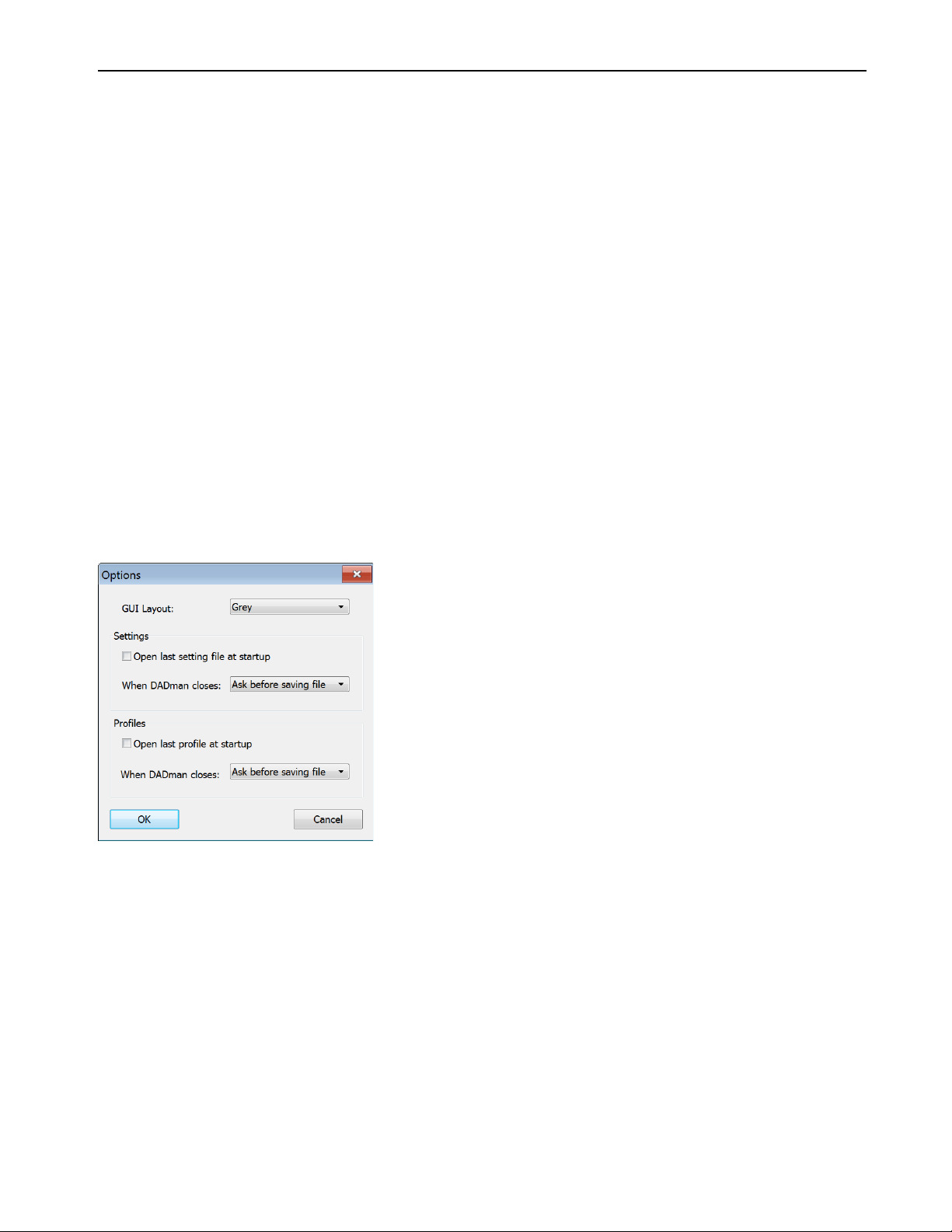
Preferences and Options
To set Preferences (Mac) or Options (Windows) for DADman:
1Choose DADman > Preferences (Mac) or Settings > Options (Windows).
2Configure the MTRX Preferences (Mac) or Options (Windows) as desired:
Open last file at startup
When enabled, DADman automatically loads the latest configuration file and downloads it to the MTRX. This
provides a well-defined starting point in case other users have changed the configuration of the MTRX. However, as multiple users can
operate the MTRX simultaneously, be careful to not disturb the work of other MTRX users on the network.
GUI Layout
Select a color scheme for DADman.
3Click OK.
Options dialog (Windows)
Chapter 3: DADman Software
12
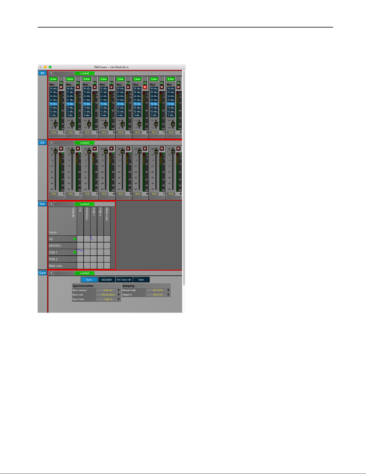
DADman Windows
The DADman window is separated into the five sections: AD, DA, Monitoring (if configured), Connections, and Configuration. Each
subsection can be shown or hidden by clicking on the corresponding button in the leftmost column.
Note that the order from left to right in which DADman shows the units is defined by the Unit ID number stored in each unit. The ID
number for any unit can be changed by editing the Unit ID field in the Device List window (Settings > Device List). You can name each
MTRX unit separately in the DADman window (just to the right of the Unit ID number at the top of each section). This name is stored
in the unit, and can be seen in the MTRX display. Names can also be assigned for each analog input and output channel. However, these
channel names are only stored in MTRX Configuration files, not in the MTRX unit itself.
DADman Window

Chapter 3: DADman Software
13
AD Section
The AD section controls any Mic/Line AD and Line AD cards in the MTRX. If there are no AD cards in the MTRX, the AD section for
that MTRX is empty.
The sliders for MIC gain can be adjusted with the mouse, the mouse scroll wheel, or with the Up and Down Arrows on your computer
keyboard. Note that using the mouse adjusts the gain by 0.1 dB increments, but the Up and Down Arrow keys adjusts the gain by 1.0 dB
increments.
DA Section
The DA section controls any DA cards in the MTRX. If there are no DA cards in the MTRX, the DA section for that MTRX is empty.
AD section
Command-click (Mac) or Control-click (Windows) any fader to set it to 0.
DA section
Chapter 3: DADman Software
14
Monitoring Section
The Monitor (Mon) section is available when the Enable monitor option is selected in the Monitor Profile Configuration Settings win-
dow (Settings > Monitor Profile). This lets you monitor defined sources and route them to defined outputs (configured in the Monitor
Profile Configuration Settings window). The Mon section also provides controls for Talkback parameters. If an optional SPQ card is in-
stalled, EQ Filter options and signal delay amounts become available (Appendix D, “SPQ Expansion Card Operation”).
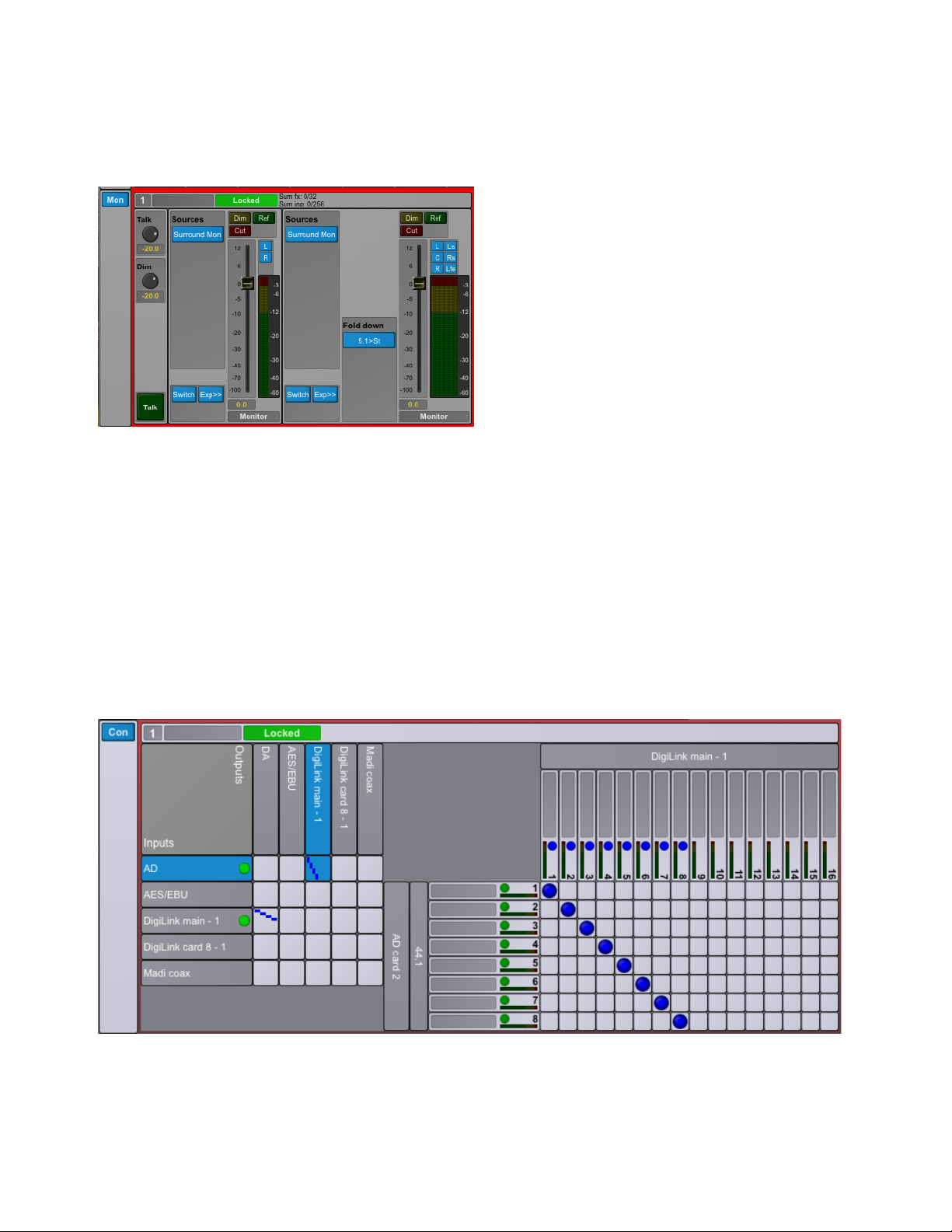
Connections Section
The Connections section provides a cross-point matrix for configuring the routing of all available analog and digital inputs and outputs
for each unit in on the network. In addition to the built-in digital I/O and DigiLink connections to and from Pro Tools, all I/O expansion
cards installed in the unit are also shown here. You can route any input channel (mono) to one or more output channels within the same
unit. All routing configurations are internal to each individual unit, so you cannot route the inputs from one MTRX unit to the outputs
of a second MTRX unit on the network.
The Connections section includes of an Overview matrix on the left and a Detailed matrix to the right, which appears when you select
a cross point between an Input Source and an Output Destination in the Overview matrix.
The left side of the Overview matrix shows all available inputs (sources) for the unit. Available outputs are displayed vertically across
the top of the Overview matrix. For example, the picture below shows the cross-point matrix for an installed 8-channel analog to digital
expansion card (AD on the left) where each input channel is routed to Pro Tools input channels 1–8 (DigiLink main – 1 on top).
Mon section
Connections section: DADman Matrix

Chapter 3: DADman Software
15
In the Detailed matrix view, a blue circle is displayed at the top of the column if an input channel is already routed to an output channel.
The circle is dark blue if an input channel that is shown in the current Detailed matrix (because the source is selected in the Overview
matrix) is already routed to the output channel. The circle is light blue if an input channel from another source, not shown in the current
Detailed matrix (because it is not selected in the Overview matrix) is already routed to the output.
In the left side of the Detailed matrix, there is a status indicator for each input channel:
Green
On a digital input, green indicates that there is a valid input and carrier. It does not indicate whether there is an audio signal pres-
ent on the channel. For an analog channel, it indicates that the expansion card is present.
Yellow
Indicates lost synchronization or mismatched sample rates.
Red
Indicates an error with the interface, such as no input signal.
To route individual input channels to one or more output channels:
1In the Overview matrix, click in the junction of an input source (Inputs are listed in the rows on the left)—such as an installed analog
input expansion card (AD) or one of the built-in digital input ports, like AES/EBU, or Pro Tools output channels (DigiLink)—and
the output destination you want (Outputs are listed in the columns on the top)—such as an installed analog output expansion card
(DA) or one of the built-in digital output ports, like MADI coax, or Pro Tools input channels (DigiLink). The junction turns blue and
the Detailed channel to channel routing matrix appears to the right.
2In the Detailed matrix, click in the junction of the input channel for the selected source (each input channel is listed in the rows on
the left) and the output channel to which you want route the signal (each output channel is listed in the columns on top). A blue circle
indicates that the input channel (row) is routed to an output channel (columns).
3To route a single input channel to multiple output channels, click in each column (outputs) in the same row (input) to make each con-
nection.
To disconnect an input and output:
Click any crosspoint connection (blue) to disconnect it.
Configuration Section
The Configuration section is divided into subsections, such as Synchronization, AES/EBU, DigiLink, MADI, and Optical 1 and Optical
2 (if present).
Shift-click to connect consecutive pairs of input channels to consecutive pairs of output channels.
Command-click (Mac) or Control-click (Windows) to connect all input channels in order to consecutive output channels in order. The
connection points are made diagonally from the top left down and to the right.
General section

Chapter 3: DADman Software
16
Synchronization
The Synchronization pane in the General sections lets you set the following MTRX parameters: Source, Sampling (sample rate), Adapt
to, Word Clock Out, and Sync term (synchronization termination). The following table shows which settings are available. Please note
that DADman will only show the settings that are relevant in the given configuration.
AES/EBU
It is recommended that you use the default settings for AES/EBU.
DigiLink
MTRX can be configured as either two Primary audio interfaces (Pri/Pri) or as a Primary audio interface and an Expansion audio inter-
face (Pri/Exp). While these can be configured to emulate HD IO or MADI I/O audio interfaces (each with up 32 channels per interface),
it is recommended that you select MTRX 32x32 with Pro Tools | HDX and HD Native systems.
Parameter Options Description
Sync Source Internal
Word clock
AES 11
Video
AES/EBU 1–8
MADI Coax
MADI Optical 1–2
Dante IP
This determines the clock source of the MTRX
Sync Out Word clock
Word clock, base
This parameter sets whether the Word Clock output should only follow the base
sample rate (44.1 kHz / 48 kHz) or follow the actual sample rate (44.1k / 48k /
88.2k / 96k / 176.4k / 192k).
Sync term. High Z
75 ohm
This parameter sets whether the Word Clock input is terminated internally in the
MTRX with 75 ohm, or left unterminated. It is strongly recommended that the
Word Clock input is terminated in 75 ohm for optimum performance.
Digi Dly (samples) Minimum, 3–31
Sampling 44.1 kHz, 48 kHz
88.2 kHz, 96 kHz
176.4 kHz, 192 kHz
DSD 64 fs, DSD 128 fs
DXD, 384 kHz
This determines the sample rate of the MTRX if the Adapt to setting is set to
Internal. If the Adapt to setting is set to any of the digital inputs, only the actual
sample rate will be shown.
Adapt to Internal
AES 11
AES/EBU 1–8
DigiLink 1–2
DigiLink Card (if installed)
MADI Coax
MADI Opt. 1–2
Dante IP
The sample rate of the MTRX can either be set manually by selecting Internal,
or it can follow any of the digital inputs. For example, if it is set to Pro Tools 1, the
sample rate will automatically follow the sample rate in your Pro Tools project.
DigiLink configuration options
Other manuals for Pro Tools MTRX
4
Table of contents
Other Avid Technology Media Converter manuals


Popular Media Converter manuals by other brands


TR-Electronic
TR-Electronic CEV115M-4096/4096 V000 PROFIBUS 85ZB20N manual

Synapse
Synapse DDP84 Installation and operation manual

ZIEHL-ABEGG
ZIEHL-ABEGG ZETADYN 2 technical information

Bose
Bose AM193147_03_V. owner's guide

CYP
CYP DCT-3 Operation manual

TR-Electronic
TR-Electronic Profibus 582 Series user manual


