Avid Technology Personal Q User manual

PN 9321-62802-00 REV A 08/10
Personal Q
for VENUE Systems

Legal Notices
This guide is copyrighted ©2010 by Avid Technology, Inc., (hereafter “Avid”), with
all rights reserved. Under copyright laws, this guide may not be duplicated in
whole or in part without the written consent of Avid.
003, 96 I/O, 96i I/O, 192 Digital I/O, 192 I/O, 888|24 I/O, 882|20 I/O,
1622 I/O, 24-Bit ADAT Bridge I/O, AudioSuite, Avid, Avid DNA, Avid Mojo,
Avid Unity, Avid Unity ISIS, Avid Xpress, AVoption, Axiom, Beat Detective,
Bomb Factory, Bruno, C|24, Command|8, Control|24, D-Command, D-Control,
D-Fi, D-fx, D-Show, D-Verb, DAE, Digi 002, DigiBase, DigiDelivery, Digidesign,
Digidesign Audio Engine, Digidesign Intelligent Noise Reduction, Digidesign
TDM Bus, DigiDrive, DigiRack, DigiTest, DigiTranslator, DINR, D-Show,
DV Toolkit, EditPack, Eleven, HD Core, HD Process, Hybrid, Impact, Interplay,
LoFi, M-Audio, MachineControl, Maxim, Mbox, MediaComposer, MIDI I/O, MIX,
MultiShell, Nitris, OMF, OMF Interchange, PRE, ProControl, Pro Tools M-Powered,
Pro Tools, Pro Tools|HD, Pro Tools LE, QuickPunch, Recti-Fi, Reel Tape, Reso,
Reverb One, ReVibe, RTAS, Sibelius, Smack!, SoundReplacer, Sound
Designer II, Strike, Structure, SYNC HD, SYNC I/O, Synchronic, TL Aggro,
TL AutoPan, TL Drum Rehab, TL Everyphase, TL Fauxlder, TL In Tune,
TL MasterMeter, TL Metro, TL Space, TL Utilities, Transfuser, Trillium Lane Labs,
Vari-Fi Velvet, X-Form, and XMON are trademarks or registered trademarks of Avid
Technology, Inc. Xpand! is Registered in the U.S. Patent and Trademark Office.
All other trademarks are the property of their respective owners.
Product features, specifications, system requirements, and availability are
subject to change without notice.
Guide Part Number 9321-62802-00 REV B 08/10

Contents iii
Contents
Chapter 1. Introduction . . . . . . . . . . . . . . . . . . . . . . . . . . . . . . . . . . . . . . . . . . . . . . . . . . . . . . . . . . . . . . . . . . . . . . . . . . . 1
Personal Q System Features. . . . . . . . . . . . . . . . . . . . . . . . . . . . . . . . . . . . . . . . . . . . . . . . . . . . . . . . . . . . . . . . . . . . . . 1
Personal Q System Components . . . . . . . . . . . . . . . . . . . . . . . . . . . . . . . . . . . . . . . . . . . . . . . . . . . . . . . . . . . . . . . . . . . 1
System Expansion Options . . . . . . . . . . . . . . . . . . . . . . . . . . . . . . . . . . . . . . . . . . . . . . . . . . . . . . . . . . . . . . . . . . . . . . . 1
Operational Requirements . . . . . . . . . . . . . . . . . . . . . . . . . . . . . . . . . . . . . . . . . . . . . . . . . . . . . . . . . . . . . . . . . . . . . . . 2
Connection Requirements . . . . . . . . . . . . . . . . . . . . . . . . . . . . . . . . . . . . . . . . . . . . . . . . . . . . . . . . . . . . . . . . . . . . . . . 2
PQ Rack Overview . . . . . . . . . . . . . . . . . . . . . . . . . . . . . . . . . . . . . . . . . . . . . . . . . . . . . . . . . . . . . . . . . . . . . . . . . . . . . 3
PQ Controller Overview . . . . . . . . . . . . . . . . . . . . . . . . . . . . . . . . . . . . . . . . . . . . . . . . . . . . . . . . . . . . . . . . . . . . . . . . . 4
Chapter 2. Connecting the Personal Q System . . . . . . . . . . . . . . . . . . . . . . . . . . . . . . . . . . . . . . . . . . . . . . . . . . . . . . 7
Connecting Personal Q System Components . . . . . . . . . . . . . . . . . . . . . . . . . . . . . . . . . . . . . . . . . . . . . . . . . . . . . . . . . . 7
Power Connections . . . . . . . . . . . . . . . . . . . . . . . . . . . . . . . . . . . . . . . . . . . . . . . . . . . . . . . . . . . . . . . . . . . . . . . . . . . . 9
Applying Power to the Personal Q System . . . . . . . . . . . . . . . . . . . . . . . . . . . . . . . . . . . . . . . . . . . . . . . . . . . . . . . . . . . . 9
Updating PQ System Firmware . . . . . . . . . . . . . . . . . . . . . . . . . . . . . . . . . . . . . . . . . . . . . . . . . . . . . . . . . . . . . . . . . . . . 9
Mounting a PQ Controller to a Microphone Stand . . . . . . . . . . . . . . . . . . . . . . . . . . . . . . . . . . . . . . . . . . . . . . . . . . . . . . . 9
Using Two Personal Q Systems . . . . . . . . . . . . . . . . . . . . . . . . . . . . . . . . . . . . . . . . . . . . . . . . . . . . . . . . . . . . . . . . . . . 11
Chapter 3. Using the Personal Q System. . . . . . . . . . . . . . . . . . . . . . . . . . . . . . . . . . . . . . . . . . . . . . . . . . . . . . . . . . . 13
Configuring the Personal Q System . . . . . . . . . . . . . . . . . . . . . . . . . . . . . . . . . . . . . . . . . . . . . . . . . . . . . . . . . . . . . . . . 13
Setting Up PQ Controllers . . . . . . . . . . . . . . . . . . . . . . . . . . . . . . . . . . . . . . . . . . . . . . . . . . . . . . . . . . . . . . . . . . . . . . . 15
Configuring Personal Q Mixers . . . . . . . . . . . . . . . . . . . . . . . . . . . . . . . . . . . . . . . . . . . . . . . . . . . . . . . . . . . . . . . . . . . 16
Controlling a Personal Q Mixer from a PQ Controller . . . . . . . . . . . . . . . . . . . . . . . . . . . . . . . . . . . . . . . . . . . . . . . . . . . . 17
Calling the Console from the PQ Controller . . . . . . . . . . . . . . . . . . . . . . . . . . . . . . . . . . . . . . . . . . . . . . . . . . . . . . . . . . 18
Locking Out PQ Controllers. . . . . . . . . . . . . . . . . . . . . . . . . . . . . . . . . . . . . . . . . . . . . . . . . . . . . . . . . . . . . . . . . . . . . . 19
Troubleshooting . . . . . . . . . . . . . . . . . . . . . . . . . . . . . . . . . . . . . . . . . . . . . . . . . . . . . . . . . . . . . . . . . . . . . . . . . . . . . 19
Appendix A. Compliance Information . . . . . . . . . . . . . . . . . . . . . . . . . . . . . . . . . . . . . . . . . . . . . . . . . . . . . . . . . . . . . . 21
Environmental Compliance. . . . . . . . . . . . . . . . . . . . . . . . . . . . . . . . . . . . . . . . . . . . . . . . . . . . . . . . . . . . . . . . . . . . . . 21
EMC (Electromagnetic Compliance). . . . . . . . . . . . . . . . . . . . . . . . . . . . . . . . . . . . . . . . . . . . . . . . . . . . . . . . . . . . . . . . 21

Personal Qiv

Chapter 1: Introduction 1
Chapter 1: Introduction
The VENUE Personal Q (PQ) system lets performers remotely
control their own monitor mixes on a VENUE system using ei-
ther a VENUE D-Show®Main or VENUE Profile™ console,
paired with a VENUE Stage Rack and a VENUE FOH Rack.
D-Show Main and Profile consoles provide eight built-in, 12 x
2 PQ mixers that can be used to create up to eight indepen-
dent stereo monitor mixes. After a PQ mixer is set up at the
mix position, it can be controlled by the mix engineer from
the Output section of the console, or by an onstage performer
using a PQ Controller.
The PQ system carries control data to and from the console, al-
lowing you to adjust PQ mixer input level, input pan/balance,
and output level. The PQ system does not carry audio signals;
audio signals for monitor mixes are output from any physical
outputs on the Stage Rack or FOH Rack.
Personal Q System Features
The Personal Q system provides remote operation of controls
on the console, and mirrors any changes made to the corre-
sponding controls on the console.
The Personal Q system consists of at least one PQ Rack and
one PQ Controller.
PQ Rack Features
• Provides connections for up to eight PQ Controllers
PQ Controller Features
• Four rotary encoder controls with LED rings for level,
pan/balance, solo, and metering of PQ mixer inputs
(1–8, L, R, and User Inputs)
• Four on/off switches for control of PQ mixer input on/off
status
• Rotary encoder control with LED ring for master volume of
PQ mixer output
• Four 6-character displays for input and control names
• Console call feature allows performer to activate call mes-
sage on console display
• Lockout feature allows performer or console operator to
temporarily lock out PQ Controller from control changes
Personal Q System Components
The following components are included in a Personal Q
system:
PQ Rack
•PQRackunit
•ACpowercord
• PQLinkCable(10ft/3m)
PQ Controller
(Up to 8 PQ Controllers can be connected to each PQ Rack)
• PQ Controller unit
• PQ Controller cable (50 ft/15 m)
System Expansion Options
The Personal Q system allows independent control of up to
eight individual PQ mixes.
PQ Racks In VENUE systems with two Stage Racks, one PQ
Rack can be connected to each Stage Rack, for a total of two
PQ Rack units. When two PQ Racks are used, dual control of
each PQ mix (up to a maximum of 8 available PQ mixers) is
possible. (This is useful when a single performer has two posi-
tions onstage.)
PQ Controllers Each PQ Rack can accommodate 8 PQ Control-
lers, for a maximum of 16 PQ Controllers (2 controllers for
each of the 8 available PQ mixers) on a VENUE system.
For more information on expansion options for VENUE sys-
tems, visit the Avid Web site (www.avid.com).

Personal Q2
Operational Requirements
Temperature and Ventilation
VENUE system components should be operated away from
heat sources and with adequate ventilation.
Storage
VENUE system components should be stored and transported
at temperatures not lower than 0 degrees F (–18 degrees C)
and not exceeding 140 degrees F (60 degrees C).
Operation
VENUE system components should be operated at tempera-
tures not lower than 40 degrees F (4 degrees C) and not ex-
ceeding 115 degrees F (46 degrees C).
Water and Moisture
VENUE system components should be operated away from
sources of direct moisture and should be kept clear of liquids
that might spill into the units.
If condensation is present on a VENUE system component,
leave the unit to dry in ambient air for at least one hour before
powering the unit on.
Cleaning and Maintenance
If you need to clean the surface of a VENUE system compo-
nent, use a dry cloth. Do not apply any cleaning solutions,
spray cleaners, or abrasives to the surface.
Connection Requirements
Power Connections
PQ Rack Each PQ Rack requires its own power connection.
Make sure your power source is correctly rated for the number
of units you are connecting. A surge protected power source
(not included) is highly recommended.
PQ Controllers Each PQ Controller is powered by the PQ Rack
through its PQ Controller cable connection.
Chapter 1: Introduction 3
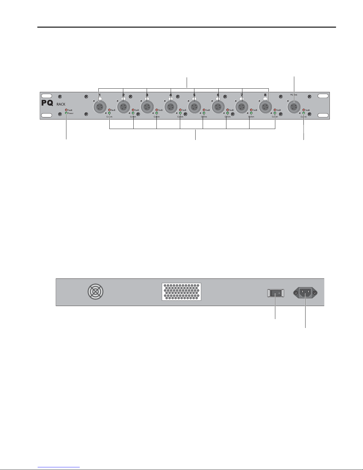
PQ Rack Overview
PQ Rack Front Panel
PQ Controller Ports Each of the 8 PQ Controller Ports accepts a
male 4-pin PQ Controller cable, for connecting a PQ Control-
ler. The PQ Controller port numbers (1–8) correspond directly
to the PQ mixer number (1–8) that is controlled on-screen or
on the console.
PQ Link Connector The PQ Link connector accepts a female
4-pin PQ Link cable, for connecting the PQ Rack to a Stage
Rack. The maximum cable length for this connection is 15 ft
(4.6 m).
PQ Rack Power/Power Fault Indicators These indicators light
to show application of power (green) and any power fault or
interruption (red) for the PQ Rack.
PQ Connection Comm/Fault Indicators These indicators light
to show active communication to a PQ Controller (green) and
any connection fault or interruption (red), for the correspond-
ing PQ Controller port.
PQ Link Comm/Fault Indicators These indicators light to show
active communication between the PQ Rack and a Stage Rack
(green) and any connection fault or interruption (red).
PQ Rack Back Panel
AC Power Connector The AC power connector accepts a stan-
dard modular AC power cord. The PQ Rack power supply is
auto-power selecting (100V to 240V, 50 Hz to 60 Hz) and au-
tomatically works when connected to an AC receptacle in any
country.
Power Switch The Power switch applies power to the PQ Rack
and activates all PQ Controllers connected to the PQ Rack.
Figure 1. PQ Rack Front Panel
PQ Controller ports (1–8) PQ Link connector (to Stage Rack)
PQ Controller Connection Fault/Comm indicators PQ Link Fault/Comm indicatorsPQ Rack Power/Power Fault indicators
Figure 2. PQ Rack Back Panel
Power switch
AC Power connector

Personal Q4
PQ Controller Overview
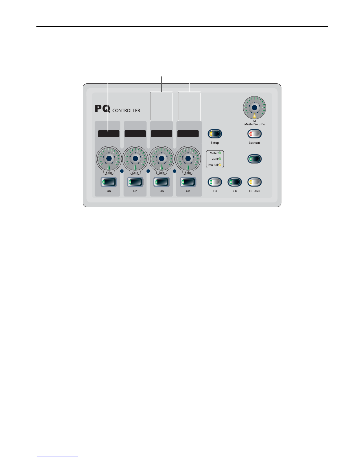
PQ Controller Top Panel
Encoder Displays The encoder displays show the name/value
of the PQ mixer input currently controlled by the correspond-
ing rotary encoder.
Rotary Encoders The rotary encoders control the currently dis-
played parameter (level or pan/balance) when turned, or solo
the currently displayed PQ mixer input when pressed. The en-
coder rings display input level or pan settings, or indicate in-
put meter levels, depending on the encoder mode.
On/Off Switches The On/Off switches turn the currently dis-
played PQ mixer input on or off.
Setup Switch The Setup switch puts the PQ Controller in
Setup mode, which displays the port number for the PQ Con-
troller, and lets you adjust display brightness and contrast on
the PQ Controller.
Inputs 1–4 Selector The Inputs 1–4 selector displays PQ mixer
inputs 1–4 on the rotary encoders and displays for adjusting
level and pan/balance.
Inputs 5–8 Selector The Inputs 5–8 selector displays PQ mixer
inputs 5–8 on the rotary encoders and displays for adjusting
level and pan/balance.
L/R/User Inputs Selector The L/R/User Inputs selector dis-
plays the Main Left, Main Right, Center/Mono, and user-as-
signable inputs on the rotary encoders and displays for adjust-
ing level and pan/balance.
Master Volume/Call Control The Master Volume/Call control
changes the PQ mixer output volume when turned, or raises a
call message on the console display when pressed.
Lockout Switch The Lockout switch temporarily locks the lo-
cal controls of the PQ Controller to prevent inadvertent
changes to controller settings. This function does not lock out
control of the PQ mixer from the console. The Lockout switch
lights when lockout is activated from the controller, and
flashes when lockout is activated from the console.
Encoder Mode Switch and Indicators The Encoder Mode
switch and indicators toggle control of input level, input
pan/balance, or input metering on the rotary encoders and
LEDs for the currently displayed input.
Figure 3. PQ Controller Top Panel
Encoder displays
Rotary
Encoders
On/Off switches Inputs 1–4
selector
Inputs 5–8
selector
L/R/User Inputs
selector
Setup switch
Master Volume/Call
control
Lockout switch
Encoder Mode
switch
and
indicators

Chapter 1: Introduction 5
PQ Controller Back Panel
PQ Controller Connector The PQ Controller connector accepts
a female 4-pin PQ Controller cable connector, for connecting
the PQ Controller to a PQ Rack. Power is provided by the PQ
Rack, through the PQ Controller cable. The maximum cable
length for this connection is 100 ft (30.5 m).
Figure 4. PQ Controller Back Panel
PQ Controller connector

Personal Q6

Chapter 2: Connecting the Personal Q System 7
Chapter 2: Connecting the Personal Q System
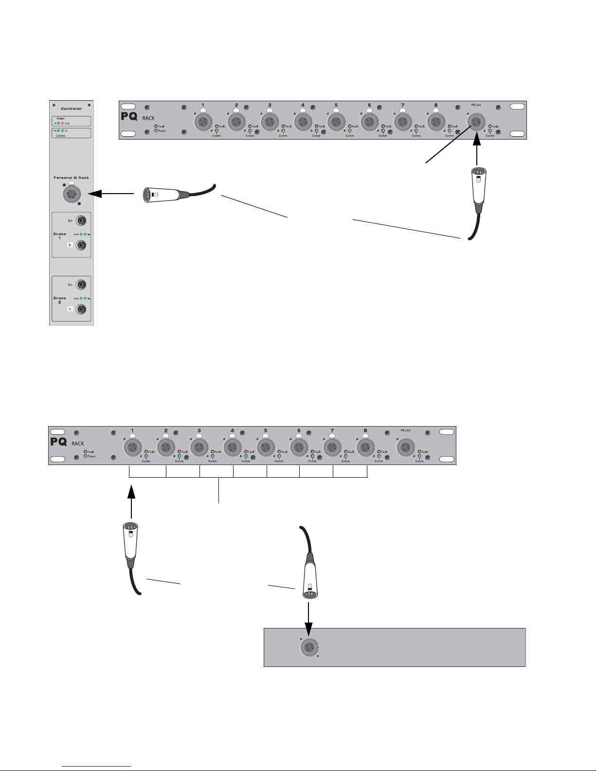
Connecting Personal Q System Components
The Personal Q System consists of a PQ Rack and from 1 to 8 PQ Controllers. The PQ Rack connects to the Controller Section of
the Stage Rack. PQ Controllers connect to the 8 available ports on the PQ Rack.
Figure 5. Personal Q System component connections (not to scale)
Stage Rack (Front)
PQ Controllers (up to 8)
PQ Rack (Front)
PQ Link cable
PQ Controller cables
(max length 15 ft/4.6 m)
(max length 100 ft/30.5 m)
PQ Controller 1
PQ Controller 2
PQ Controller 3
PQ Controller 4
PQ Controller 5
PQ Controller 6 PQ Controller 7
PQ Controller 8
12345678Ports
Personal Q8
Connecting the PQ Rack to the Stage Rack
The PQ Rack connects to the Stage Rack with the PQ Link cable. The maximum length permissible for the PQ Link cable is 15 feet
(4.6 meters).
Connecting PQ Controllers to the PQ Rack
PQ Controllers connect to any of the PQ Controller ports 1–8 on the PQ Rack with PQ Controller cables. The Controller port
number (1–8) corresponds directly to the PQ mixer number (1–8) on the console. The maximum length permissible for the PQ
Controller cable is 100 feet (30.5 meters).
Figure 6. PQ Link cable connection between Stage Rack and PQ Rack
PQ Rack
Stage Rack (Controller Section)
PQ Link connector
PQ Link cable
Figure 7. PQ Controller cable connection between PQ Rack and PQ Controller
PQ Rack
PQ Controller (Back)
PQ Controller ports
PQ Controller cable

Chapter 2: Connecting the Personal Q System 9
Power Connections
PQ Rack
The power supply in the PQ Rack is auto-power selecting
(100V to 240V, 50 Hz to 60 Hz). A modular IEC power cable is
provided.
PQ Controllers
PQ Controllers are powered through the connection to the PQ
Rack. No additional power connection is required.
Applying Power to the Personal Q
System
PQ Rack
The PQ Rack can be connected to the Stage Rack and powered
up or down at any time before or after power up of the VENUE
system.
PQ Controllers
PQ Controllers can be connected to or disconnected from a
PQ Rack at any time.
Updating PQ System Firmware
If new firmware is available for a PQ Rack or PQ Controller
unit, it is automatically downloaded to the unit when it is
connected to the VENUE system. The LEDs on the Rack or
Controller unit flash in sequence to indicate firmware is being
updated. The unit is unavailable during the firmware update.
Firmware download status can be monitored on-screen from
the Devices tab of the Options page.
Mounting a PQ Controller to a
Microphone Stand
A PQ Controller can be mounted on microphone stand using
a specially-designed bracket.
To mount a PQ Controller on a microphone stand:
1 Attach the large mounting bracket to the bottom panel of
the PQ Controller with 4 of the provided machine screws. Do
not fully tighten the screws.
1 Attach the small mounting bracket to the back panel of the
PQ Controller with 2 of the provided machine screws. Do not
fully tighten the screws.
2 Line up the holes in the two brackets and tighten the screws
on each bracket.
Firmware updates can take several minutes to complete.
Make sure to allow time for all connected units to finish
the update process.
Attaching the large mounting bracket to the bottom of a PQ Controller
Attaching the small mounting bracket to the back of a PQ Controller

Personal Q10
3 Affix the PQ Controller mounting bracket to any standard
microphone mount, and secure it with a nut or with a micro-
phone boom (shown below).
PQ Controller affixed to a microphone mount

Chapter 2: Connecting the Personal Q System 11
Using Two Personal Q Systems
In VENUE systems with two Stage Racks, a complete Personal Q system can be connected to each Stage Rack. When two
Personal Q systems are connected in this manner, their PQ Controllers control the corresponding PQ mixers in parallel.
Figure 8. System connections with two Stage Racks and parallel PQ systems (not to scale)
Stage Rack 1
PQ Rack 1
Stage Rack 2
PQ Rack 2
PQ 1-1
PQ 1-2
PQ 1-3
PQ 1-4
PQ 1-5
PQ 1-6
PQ 1-7
PQ 1-8
PQ 2-1
PQ 2-2
PQ 2-3
PQ 2-4
PQ 2-5
PQ 2-6
PQ 2-7
PQ 2-8
(PQ Mixer 1)
(PQ Mixer 2)
(PQ Mixer 3)
(PQ Mixer 4)
(PQ Mixer 5)
(PQ Mixer 6)
(PQ Mixer 7)
(PQ Mixer 8)
12345678Ports 12345678Ports

Personal Q12

Chapter 3: Using the Personal Q System 13
Chapter 3: Using the Personal Q System
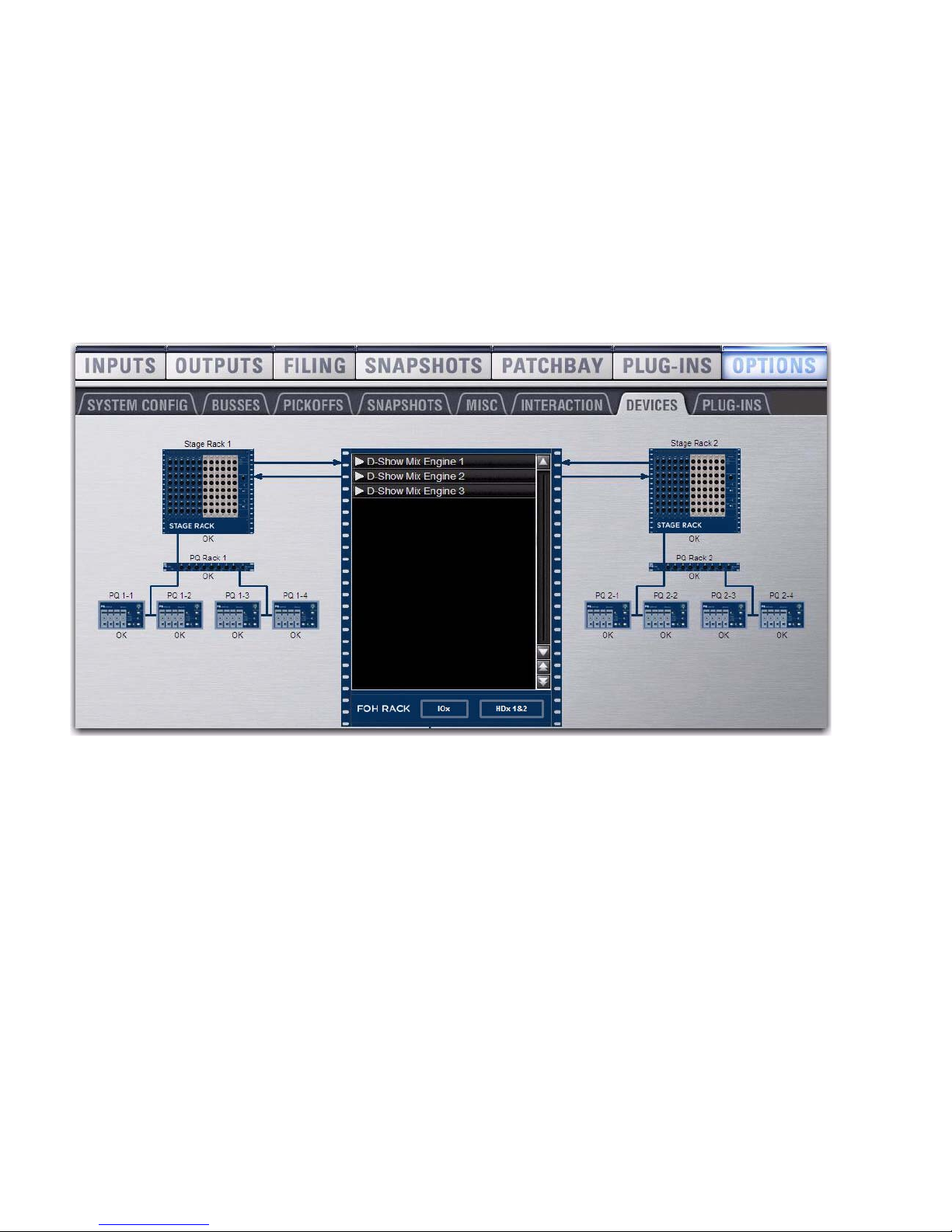
Configuring the Personal Q System
When properly connected to an enabled Stage Rack, PQ Racks and PQ Controllers are automatically recognized and assigned
numbers by the VENUE software. When a PQ Controller is detected, the Controller Detected indicator lights in the corresponding
Personal Q Mixer window on-screen.
To view the Personal Q System configuration:
Go to the Options page and click the Devices tab. Connected PQ Racks and PQ Controllers appear beneath the corresponding
Stage Rack, and are automatically assigned numbers.
Figure 9. Personal Q System connections in the Devices tab of the Options page, showing PQ Rack and PQ Controller numbering
Personal Q14
PQ Rack Numbering
Each PQ Rack number is automatically assigned, and corresponds to the number of the Stage Rack where it is connected.
PQ Controller Numbering
Each PQ Controller number is automatically assigned, and corresponds to the number of the PQ Rack and the PQ Controller port
where it is connected. For example, a PQ Controller connected to port 4 on PQ Rack 2 is numbered “PQ 2-4.”
The last digit of the PQ Controller number determines which of the 8 available PQ mixers it controls. For example, PQ Controllers
numbered “PQ 1-3” and “PQ 2-3” would both control PQ mixer number 3 (“PQ 3”).
To assign a PQ Controller to control a specific PQ mixer:
Connect the PQ Controller to a PQ Rack controller port whose number corresponds to the PQ mixer you want to control.
Figure 10. Personal Q System connections in the Devices tab of the Options page, showing a configuration with two PQ systems
Chapter 3: Using the Personal Q System 15
Setting Up PQ Controllers
You can view a PQ Controller’s number and adjust its display settings directly from the controller.
Viewing a PQ Controller Number
To view a PQ Controller’s number from the PQ Controller unit:
1 Press the Setup switch on the PQ Controller. The leftmost display on the PQ Controller shows its port assignment, which cor-
responds to PQ mixer that it controls.
2 Press the Setup switch again to exit Setup mode.
Adjusting PQ Controller Display Settings
To adjust the brightness and contrast of a PQ Controller’s displays:
1 Press the Setup switch on the PQ Controller.
2 Turn the third encoder to adjust display contrast.
3 Turn the fourth encoder to adjust display brightness.
4 Press the Setup switch again to exit Setup mode.
Figure 11. PQ Controller display and encoder functions in Setup mode
PQ Controller
Number Display
Display
Contrast Display
Brightness
controlscontrols

Personal Q16
Configuring Personal Q Mixers
The 12 Inputs for each PQ mixer connected to your Stage Rack can be any combination of the following 35 potential sources:
• 24 shared Aux and Group sources
• 3 Mains sources (LCR or LR+M)
•8UserInputsources
User Inputs can be input channels, FX Returns, physical Stage Rack inputs, physical FOH Rack inputs, or inputs from a Pro Tools
Recording/Playback option (HDx or FWx)
• One or more of the 8 available user inputs can be sent to one or more Matrix or PQ mixers.
• Input source assignment and user input assignment can be stored on a per-snapshot basis.
• The input sources for PQ mixers are configured as Pre- or Post-Fader in the Pickoffs tab of the Options page.
Input labels (1–8, Left, Right, C/Mono and User) are only intended as a guide, to help you navigate the controls. In use, any input
source can be assigned to any mixer input (for example, Left doesn't always have to be assigned to the Left input of a PQ mixer).
Personal Q Mixer in Outputs page on-screen
Currently selected PQ Mixer
PQ output
PQ input controls
level and
controls
Controller Detected indicator
Controller Lockout controls and indicators
Table of contents
Other Avid Technology Music Equipment manuals

Avid Technology
Avid Technology Pro Tools Quartet User manual

Avid Technology
Avid Technology SC264 User manual

Avid Technology
Avid Technology Pro Tools S6 Master Post Module User manual

Avid Technology
Avid Technology DF70 User manual

Avid Technology
Avid Technology Pro Tools S6 Master Post Module User manual

Avid Technology
Avid Technology Pro Tools S6 Master Post Module User manual

Avid Technology
Avid Technology SC263 User manual


