Avigilon 1L-HD-LP-35 User manual
Installation Guide
Avigilon™ License Plate Recognition System Models:
1L-HD-LP-35, 1L-HD-LP-50, 1L-HD-LP-75, 1L-HD-LP-100 and 2L-
HD-LP-40
SUPPORT [email protected] | 1300 65 44 33 | suretek.com.au

lEN: For a copy of this manual in your preferred language, see the Avigilon LPR Design andInstallation
Guide in the Avigilon Resource Center.
lFR : Pour obtenir un exemplaire de ce manuel dans la langue de votre choix, reportez- vous au
Conception et guide d'installation LPR d'Avigilon sur l'Avigilon Centre de ressources.
lES: Si desea una copia de este manual en su idioma preferido, consulte la Guía de instalación y diseño
LPR de Avigilon en el Centro de recursos de Avigilon.
lIT: Per una copia del presente manuale nel propria lingua, fare riferimento alla Guida di progettazione ed
installazione Avigilon LPR nel Avigilon centro risorse.
lDE: Eine Kopie dieses Handbuchs in Ihrer bevorzugten Sprache finden Sie im Avigilon Resource Center
unter Avigilon LPR-Design und Installationsanleitung.
lPT-BR: Para obter uma cópia deste manual em seu idioma preferido, veja o Guia de projeto e instalação
do LPR da Avigilon no Avigilon Centro de recursos.
lRU: Копию данного руководства по проектированию и установке Avigilon LPR можно загрузить с
Avigilon Ресурсный центр.
lZH: 如需适用您的语言的手册副本,请参阅 Avigilon 资源中心的 《 Avigilon LPR 设计和安装指南》。
2
SUPPORT [email protected] | 1300 65 44 33 | suretek.com.au

©2013 -2017,Avigilon Corporation. All rights reserved. AVIGILON, the AVIGILON logo, AVIGILON CONTROL
CENTER, ACC and TRUSTED SECURITY SOLUTIONS are trademarks of Avigilon Corporation. Other names
mentioned herein may be the trademarks of their respective owners. The absence of the symbols ™ and ® in
proximity to each trademark in this document is not a disclaimer of ownership of the related trademark. Avigilon
Corporation protects its innovations with patents issued in the United States of America and other jurisdictions
worldwide: avigilon.com/patents. Unless stated explicitly and in writing, no license is granted with respect to
any copyright, industrial design, trademark, patent or other intellectual property rights of Avigilon Corporation or
its licensors.
This document has been compiled and published covering the latest product descriptions and specifications.
The contents of this document and the specifications of the products discussed herein are subject to change
without notice. Avigilon Corporation reserves the right to make any such changes without notice. Neither
Avigilon Corporation nor any of its affiliated companies: (1) guarantees the completeness or accuracy of the
information contained in this document; or (2) is responsible for your use of, or reliance on, the information.
Avigilon Corporation shall not be responsible for any losses or damages (including consequential damages)
caused by reliance on the information presented herein.
Avigilon Corporation
avigilon.com
920-0028A
Revision: 7 - EN
20170308
3

Table of Contents
Introduction 6
Site Design 7
LPR Camera Selection 7
Required Number of Servers 7
System Requirements 7
Selecting a Mounting Location 8
Overhead Mounting 8
Roadside Mounting 9
Maximum Cable Length 10
Field Of View 10
Installation 11
Package Contents 11
Installation Steps 11
Connecting Cables to the Camera 11
(Optional) Adding an Overview Camera 12
Connecting External Power 13
Mounting the LPR Enclosure 13
Mounting the Power Supply Unit 15
PSU Cable Connections 15
PSU to LPR Kit Connections 15
Connecting Cables in the PSU 16
Positioning the HD LPR Capture Kit 18
Adjusting the Mounting Bracket 18
Adjusting the Enclosure 19
Configuring LPR in the ACC Software 21
Configuring the Camera 21
Setting Up License Plate Recognition 22
Configuring the Watch List 22
Adding Licenses to the Watch List 22
Deleting a License Plate from the Watch List 23
Exporting a Watch List 23
Importing a Watch List 23
Monitoring Detected License Plates 23
License Plate Overlay 23
Reviewing License Plate Matches 24
4

Performing a License Plate Search 24
Viewing Search Results 24
Verification Test 26
Specifications 27
Limited Warranty & Technical Support 28
5

Introduction
This guide provides instructions on how to install a License Plate Recognition (LPR) system using the Avigilon HD
LPR Capture Kit.
For information on how to select an appropriate LPR camera model and mounting location, see Site Design on
the next page.
For information on how to install and position the HD LPR Capture Kit, see Installation on page11
For information on how to use the License Plate Recognition feature in the AvigilonControl Center™ (ACC), see
Configuring LPR in the ACC Software on page21
Introduction 6

Site Design
This section will help you select an appropriate LPR camera model, number of NVR servers, and mounting
location based on your video surveillance requirements. It is important to read this section before installing the
HD LPR Capture Kit to ensure LPR accuracy.
LPR Camera Selection
The target distance is the physical distance between the LPR camera and the license plate detection area.
Each HD LPR Capture Kit model is calibrated for a specific target distance. Refer to the table below to select the
appropriate kit:
Target Distance (ft [m]) Single Lane Dual Lanes
35 [11] 1L-HD-LP-35 N/A
50 [15] 1L-HD-LP-50 N/A
75 [23] 1L-HD-LP-75 N/A
100 [30] 1L-HD-LP-100 N/A
40 [12] N/A 2L-HD-LP-40
Required Number of Servers
The Avigilon HD LPR Capture Kit is designed to cover a single traffic lane of 10 ft (3m) or two adjacent traffic
lanes. The maximum number of lanes that can be monitored on a single server depends on the target vehicle
speed and the mounting height.
Speed (mph [km/h]) Maximum number of lanes per NVR
(Recommended Overhead)
Maximum number of lanes per NVR
(Maximum Overhead or Roadside)
0-20 [0-32] 4 2
20-30 [32-50] 2 1
30-40 [50-65] 1 1
40-60 [65-100] 1 Not recommended
NOTE: The Avigilon LPR software should only be run on Avigilon HD NVR servers or machines with similar
specifications. For HDNVR servers, it is recommended that you use an additional processor to supplement the
processing requirements of the LPR.
System Requirements
The Avigilon LPR software can only run on the following operating systems. Make sure the servers are using one
of these operating systems before you install the LPR software.
Site Design 7

lWindows Vista 64-bit
lWindows Server 2008
lWindows 7
Selecting a Mounting Location
You must select a mounting location before you can install the HD LPR Capture Kit. It is important to mount the kit
in an appropriate location to optimize the LPR accuracy.
The kit can be mounted in the overhead or roadside position. The LPR camera can recognize vehicles traveling
at up to 100 km/h (60 mph) when mounted in the recommended overhead mounting height, but the maximum
detectable speed decreases to 65 km/h (40 mph) when mounted in the maximum overhead mounting height or
when mounted in the roadside position.
Overhead Mounting
In overhead mounting, the HD LPR Capture Kit is mounted directly above the vehicle path. Refer to the following
tables for recommended and maximum mounting heights for each HD LPR Capture Kit model and their
corresponding horizontal distances to the license plate detection area.
Overhead Recommended Mounting Height:
HD LPR Capture Kit Target Distance (ft [m]) Recommended Mounting
Height (ft [m])
Horizontal Distance (ft
[m])
1L-HD-LP-35 35 [11] 9 – 12 [2.8 – 3.6] 33 [10]
1L-HD-LP-50 50 [15] 13 – 17 [4.0– 5.2] 48 [14.5]
1L-HD-LP-75 75 [23] 19 – 26 [5.9 – 7.8] 72 [22]
1L-HD-LP-100 100 [30] 26 – 34 [7.9 – 10] 95 [29]
2L-HD-LP-40 40 [12] 10 – 14 [3.1 – 4.2] 38 [11.5]
Overhead Maximum Mounting Height:
HD LPR Capture Kit Target Distance (ft [m]) Maximum Mounting
Height (ft [m])
Horizontal Distance (ft
[m])
1L-HD-LP-35 35 [11] 18 [5.5] 30 [9.2]
1L-HD-LP-50 50 [15] 25 [7.5] 43 [13]
1L-HD-LP-75 75 [23] 38 [11] 65 [20]
1L-HD-LP-100 100 [30] 50 [15] 87 [26]
2L-HD-LP-40 40 [12] 20 [6.1] 35 [11]
Selecting a Mounting Location 8

Figure 1: Overhead mounting (top view)
Figure 2: Overhead mounting (side view)
Roadside Mounting
If overhead mounting is not possible, then use roadside mounting. In roadside mounting, the HD LPR Capture Kit
is often pole-mounted on the side of the road. Refer to the following table for the maximum mounting height and
offset distance for each HD LPR Capture Kit model. Select the shortest target distance that results in a practical
mounting location.
NOTE: The dual lane kit (2L-HD-LP-40) should not be mounted in the roadside position.
Roadside Mounting Height and Offset:
HD LPR Capture Kit Target Distance (ft
[m])
Max Mounting
Height (ft [m]) Max Offset (ft [m]) Horizontal Distance
(ft [m])
1L-HD-LP-35 35 [11] 12 [3.6] 12 [3.6] 32 [10]
1L-HD-LP-50 50 [15] 17 [5.2] 17 [5.2] 46 [14]
1L-HD-LP-75 75 [23] 26 [7.8] 26 [7.8] 69 [21]
1L-HD-LP-100 100 [30] 34 [10] 34 [10] 93 [28]
Roadside Mounting 9

Figure 3: Roadside mounting (top view)
Figure 4: Roadside mounting (side view)
Maximum Cable Length
The distance between the Power Supply Unit (PSU) and the LPR kit is limited by the maximum length of the
power and network cables. Refer to the following table to select a mounting location for the PSU.
Table 6: Wire Gauge vs. Max. Distance
Wire Gauge (AWG) Max. Distance (m [ft])
18 4.0 [13]
20 2.5 [8.4]
22 1.6 [5.3]
24 1.0 [3.3]
Field Of View
The camera field of view is the area that is visible in the video image.
When a moving vehicle is not in the field of view, it is important that the LPR camera is not aimed at anything that
could be interpreted as a series of alphanumeric characters such as a billboard or road sign. The LPR system
may recognize this as a license plate and generate inaccurate results.
Maximum Cable Length 10

Installation
After you have selected a mounting location, you can install the HD LPR Capture Kit.
Package Contents
Ensure the package contains the following:
lAvigilon™ HD LPR Camera
lAvigilon™ HD LPR Enclosure
lPower Supply Unit (PSU)
l3 mm Hex key for enclosure
l2 x Network Cables (inside enclosure)
lCamera Power Connector Block
lOverview camera adapter
lUNC 20 bolt and washers
lMounting assembly kit
lMounting bracket
lMounting bracket pad
l4 mm Hex key
l10 x Shims (Single Lane only)
l4 x Shim screws
Installation Steps
Complete the following steps to install the device:
Connecting Cables to the Camera
Important: Do not adjust the LPR camera inside the enclosure. It is calibrated for a specific target distance.
CAUTION — Do not tilt the enclosure backwards when the back panel is removed. The camera may
slide out.
1. Loosen the four screws at the back of the enclosure and remove the back panel.
2. To add an overview camera, see (Optional) Adding an Overview Camera on the next page
3. Connect the terminal labeled J8 (CAT5) to the Ethernet port of the LPR camera using the network cable
provided.
4. If Power over Ethernet (PoE) is not available, proceed to Connecting External Power on page13
5. Reinstall the back panel of the enclosure.
Installation 11
(Optional) Adding an Overview Camera
You can install an overview camera in the LPR enclosure to record the wider surveillance area, which is useful for
identifying a vehicle model or driver, or capturing video before and after an incident.
NOTE: It is recommended that you use Avigilon HD H.264 IP Camera models H3-B2 or H3-B3 as overview
cameras.
Complete the following steps to install an overview camera:
1. Loosen the four screws at the back of the enclosure and remove the back panel.
2. Remove the network cables from the terminals labeled J8 (CAT5) and J9 (CAT5) .
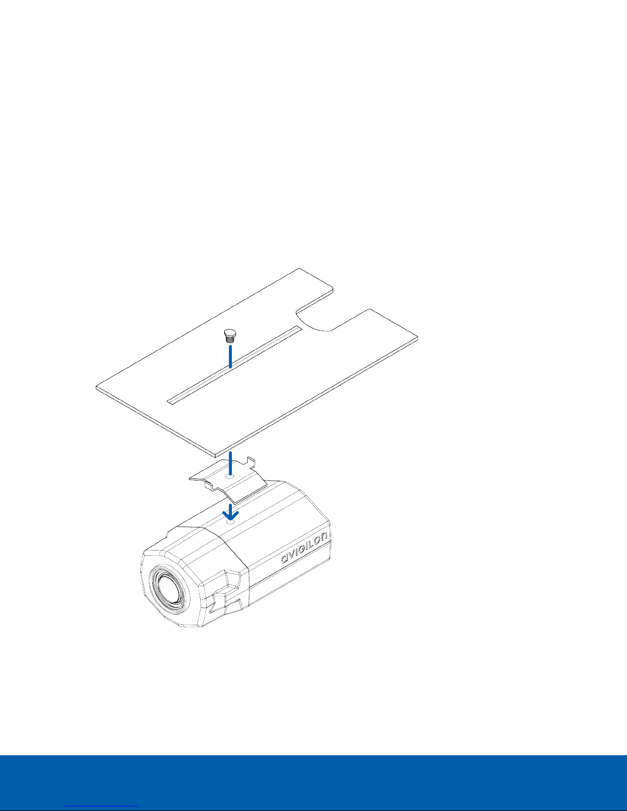
3. Slide out the metal mounting plate below the LPR camera.
Be careful not to touch the LPR camera or lens.
4. Use the provided UNC 20 bolt and camera adapter to attach the overview camera to the mounting plate.
5. Slide the mounting plate and overview camera into the enclosure. Ensure that the bolt has sufficient
clearance from the LPR camera.
Be careful not to damage the circuit board below.
6. Connect the terminal labeled J9 (CAT5) to the Ethernet port of the overview camera using the network
cable provided.
(Optional) Adding an Overview Camera 12

7. Connect the terminal labeled J8 (CAT5) to the Ethernet port of the LPR camera using the network cable
provided.
8. If Power over Ethernet (PoE) is not available, proceed to Connecting External Power below
9. Reinstall the back panel of the enclosure.
Connecting External Power
NOTE: Do not perform this procedure if PoE is used.
1. To connect power to the LPR camera, connect the terminal labeled J2 (Power Camera 1) to the power
connector block of the LPR camera.
2. To connect power to the overview camera, connect the terminal labeled J3 (Power Camera 2) to the
power connector block of the overview camera.
Mounting the LPR Enclosure
Before you can mount the HD LPR Capture Kit, you must choose a mounting location. For more information, see
Site Design on page7
Complete the following steps to mount the enclosure:
NOTE: The required cameras should already be connected inside the enclosure.
Connecting External Power 13
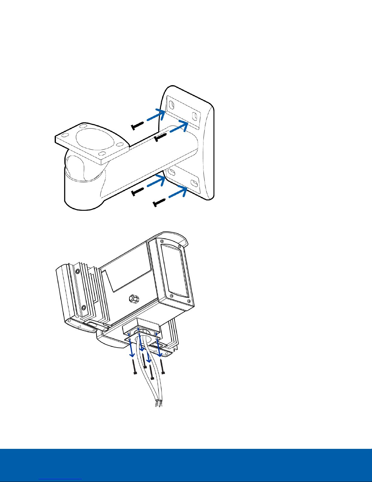
1. Drill four mounting holes and a cable entry hole into the mounting surface.
2. Attach the mounting bracket to the mounting surface.
lUse screws that are appropriate for the mounting surface.
lIt is recommended that you apply silicone sealant into the mounting holes underneath the screw
heads.
3. Use the provided 3mm Hex key to remove the four screws from the base of the enclosure.
Mounting the LPR Enclosure 14

4. Pull the required cables through the mounting arm and into the cable entry hole. Then, secure the
enclosure to the mounting arm.
Mounting the Power Supply Unit
Important: The PSU must be mounted within a certain distance from the LPR kit. For more information, see
Maximum Cable Length on page10
Install the PSU within the maximum distance using the four M4 mounting holes at each corner of the unit.
Do not connect power to the PSU until all other cable connections have been established.
PSU Cable Connections
PSU to LPR Kit Connections
The HD LPR Capture Kit is powered and connected to the network through the PSU.
Mounting the Power Supply Unit 15

1. LPR camera power cable
2. LPR camera network cable
3. Network cable from switch (for LPR camera)
4. Network cable from switch (for optional overview camera)
5. Power supply cable to PSU
Connecting Cables in the PSU
Refer to the following diagram for the locations of the different connectors:
Connecting Cables in the PSU 16

NOTE: The cable glands are designed for cables between 0.15 – 0.30 inches (4 – 8 mm) in diameter. For thinner
cables, thicken the cable with electrical tape at the point of contact with the gland to ensure a tight fit. Unused
glands should be plugged or sealed.
1. Connect the black power cable from the LPR camera to the PSU:
a. Pull the cable through the first cable gland (#1 in the diagram)
b. Connect the red and black wires to J4 (Lamp Power):
oRed — positive
oBlack — negative
c. Connect the purple and white wires to J8 (15 V Aux Power):
oPurple — positive
oWhite — negative
2. Connect the gray network cable from the LPR camera to the PSU:
a. Pull the cable through the second cable gland (#2 in the diagram)
b. Connect the wires to the appropriate terminals in the punch down block labeled J1 (Camera
Combined Feed):
oOrange/ White — terminal 1
oOrange — terminal 2
oGreen/ White — terminal 3
oBlue — terminal 4
oBlue/ White — terminal 5
Connecting Cables in the PSU 17

oGreen — terminal 6
oBrown/ White — terminal 7
oBrown — terminal 8
3. Connect a network cable from a network switch to the PSU:
a. Pull the cable through the third cable gland (#3 in the diagram) and terminate it with an RJ-45 jack.
b. Connect this cable to J2 (Camera 1).
4. If you are using an overview camera, connect another network cable from the network switch to the PSU:
a. Pull the cable through the fourth cable gland (#4 in the diagram) and terminate it with an RJ-45 jack.
b. Connect this cable to J3 (Camera 2).
5. Connect a 24V AC/DC power supply cable to the PSU:
NOTE: It is recommended that you use a 24 V (secondary) 100 VA transformer.
a. Pull the cable through the fifth cable gland (#5 in the diagram).
b. Connect the red and black wires to J6 (Low Voltage AC/DC Input) terminal.
oRed — positive
oBlack — negative
Tip: If power is supplied to the PSU, there will be a red glow from both IR panels. You can verify this by taking a
photo of the IR panels with a phone camera. The red glow will be more visible in the photo.
CAUTION — Do not adjust any of the potentiometers in the PSU.
Positioning the HD LPR Capture Kit
Adjusting the Mounting Bracket
The Avigilon HD LPR Capture Kit is pre-calibrated for a specific target distance as indicated by the model
number. It is important to aim the camera at the appropriate distance.
Positioning the HD LPR Capture Kit 18

1. Use the 4mm Hex key provided to loosen the screw at the head of the mounting bracket.
2. Adjust the head as required.
3. Tighten the screw to secure the head.
Adjusting the Enclosure
When the HD LPR Capture Kit is mounted in the roadside position, vehicle license plates may appear skewed.
To improve LPR accuracy, you can use the shims provided to adjust the enclosure such that vehicle license
plates appear horizontal in the image.
1. Park a vehicle in the center of the field of view.
2. View the image of the vehicle. If the image is horizontal, you do not need to install the shims.
3. If the vehicle’s license plate is not horizontal in the image, unscrew the 2 screws in the base of the
enclosure on the side that needs to be corrected and replace them with shim mounting screws . Do not
tighten.
4. Install a shim under each shim mounting screw at the enclosure/ mounting bracket interface.
Repeat until the license plate is horizontal in the image. Up to 3 shims per screw may be necessary.
Adjusting the Enclosure 19
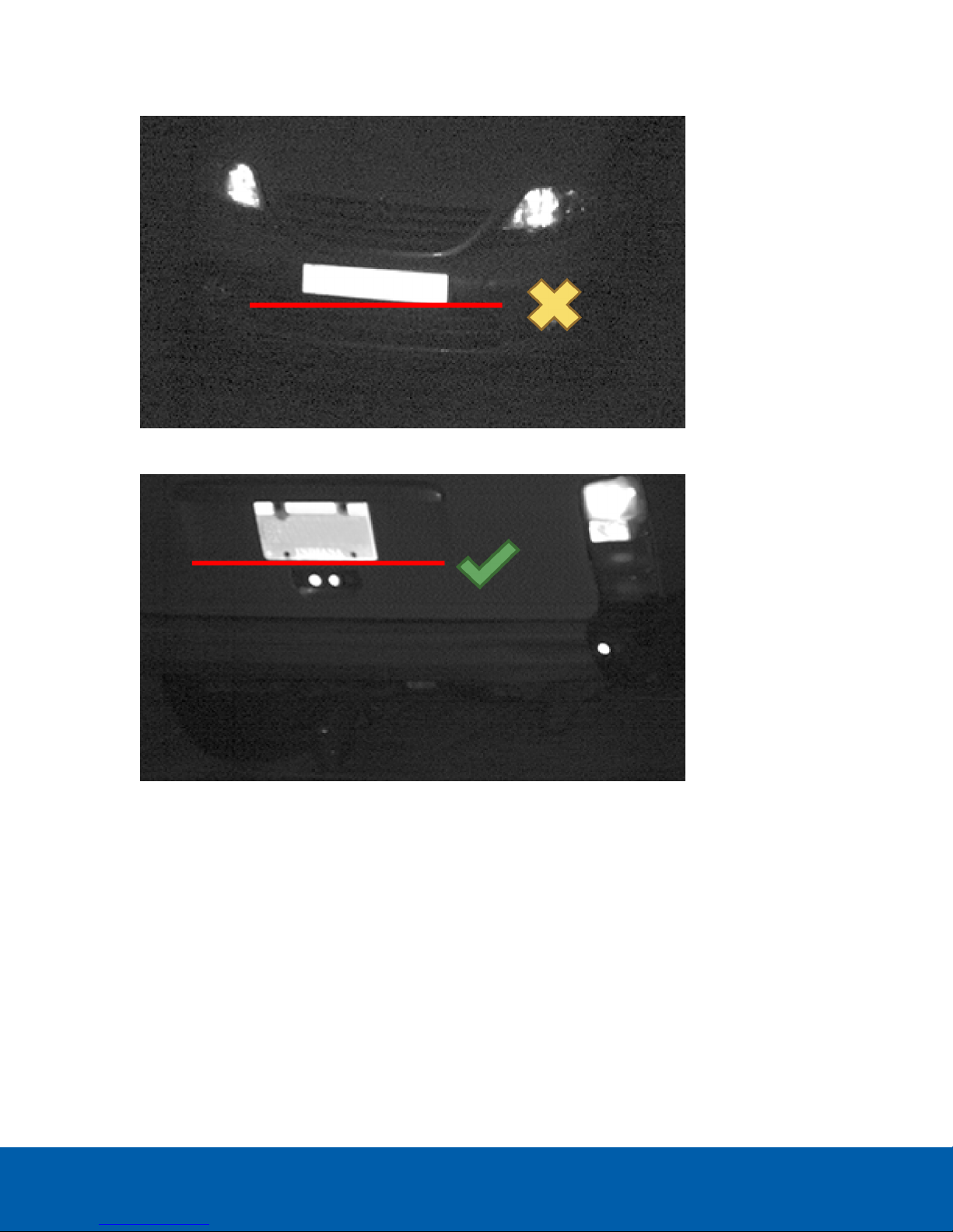
5. Tighten the screws at the base of the enclosure.
Figure 5: Tilted license plate (incorrect)
Figure 6: Horizontal license plate (correct)
Adjusting the Enclosure 20
This manual suits for next models
4
Table of contents
Other Avigilon Security System manuals

Popular Security System manuals by other brands


Secure
Secure USAB-1 operating instructions

B&B
B&B 480 SERIES Operation & maintenance manual

ADEMCO
ADEMCO VISTA-20P Series Installation and setup guide

Inner Range
Inner Range Concept 2000 user manual

Johnson Controls
Johnson Controls PENN Connected PC10 Install and Commissioning Guide

Aeotec
Aeotec Siren Gen5 quick start guide


