AVIRE MRL DCP User manual

MRL DCP
Installation Guide
Ref No MU-875X0AV10A-GB Version 1
AC-2CD00-100-F-20-000
PRODUCT DESCRIPTION
The Machine-Room-Less (MRL) DCP is installed inside the landing controller panel and provides an
information gateway between all compatible connected devices in the elevator shaft and our online
monitoring platform the Avire Hub.
The MRL DCP has an in-built network signal strength scanner to measure the level of signal in its intended
installation location.
Use the MRL DCP as a two-way data link to:
- congure and monitor devices via MK CANBus using the Avire Hub
- remotely test elevators by connecting Lift HAWK
- monitor Panachrome+ light curtains
- update display layouts
- connect EN81-28:2018 compliant emergency communication
ITEMS REQUIRED FOR INSTALLATION
In the Box - MRL DCP
+ MRL DCP
+ P-3.5 H-2V connector (x1)
+ P-3.5 H-3V connector (x1)
+ P-3.5 H-4V connector (x1)
+ P-3.5 H-5V connector (x1)
+ Manual
In the Box - Battery Backup
+ Battery Backup
+ P-3.5 H-3V connector (x1)
+ P-5 BL2 connector (x1)
+ Wiring
Not Included
+ Screwdriver
+ DIN rail (check Lift Controller
for location to x MRL DCP &
Battery Backup)

ELEVATOR SAFETY
Note: All Health & Safety protocols must be followed and all necessary precautions
must be taken before installation.
SETTING UP THE MRL DCP
Avire SIM cards come activated and ready to be installed.
If a non-Avire SIM card is used please activate this before installation, checking with
the SIM provider on how to do this.
1. Insert the SIM card into connector J4 pressing it until it clicks.
2. Connect the antenna on the MRL DCP to J2
and make sure it is completely screwed in.
NOTE: Only use antennas authorised by Avire.
1
*Please refer to pages 11 and 12 for the full picture and connector information
J4*
J2*
You can check the status of the power supply, battery, connection, coverage or
Subscriber Line Interface Circuit (SLIC) at any time by referring to the LED Indicators
(page 13)
3. Connect the power supply (between 10V DC to 30V DC) to J1 using
the 3-pin connector supplied with the unit or connect the device
to the Battery Backup (supplied separately, please refer to page
14 for set up).
4. Verify that the RUN LED ( ) ashes green (this will take a
maximum of 60 seconds). If the SIM LED ( )ashes red, make
sure the SIM is inserted correctly and the SIM PIN is unlocked on
non-Avire SIMs (please refer to page 3, “SIM card unlocking”).
J1*

+Once nished return SW1 dipswitch 1 back to OFF.
7. If a non-Avire SIM card is used, APN settings must be set prior to conguring it
on the Avire Hub (please refer to “Setting Parameters on non-Avire SIM cards” on
page 3). If the SIM LED is red, please refer to “SIM Card unlocking” on page 3.
8. Once the device is set-up and connected, please add it to the Avire Hub online
platform for elevator and device monitoring options (http://hub.avire-global.com/).
Please use the “Help” section for tutorials on how to use the Avire Hub.
2
6. If required, connect additional products to the CANBus via J7 (pin1= Gnd, pin2= CAN L,
pin3= CAN H, pin4= Vcc)
*Please refer to pages 11 and 12 for the full picture and connector information
J7*
5. Check the signal strength by using the built-in network
signal strength scanner. To use this function:
+Turn SW1 dipswitch 1 to ON (check dipswitch 4 is also ON)
+LEDs on the front of the DCP unit will show the network
signal level SW1*

SIM CARD UNLOCKING
Important Note: An Avire SIM card doesn’t have a SIM PIN code, so if the SIM LED is
ashing red please make sure it has been inserted correctly. The SIM PIN code for
other network providers may vary; if there is one it is usually found on the outer
plastic case of the SIM card.
If the SIM LED is ashing red, you may need to add the SIM PIN code to the DCP or
delete it. In this case, follow either of these steps:
3
SETTING PARAMETERS ON NON AVIRE SIMS
OPTION 1
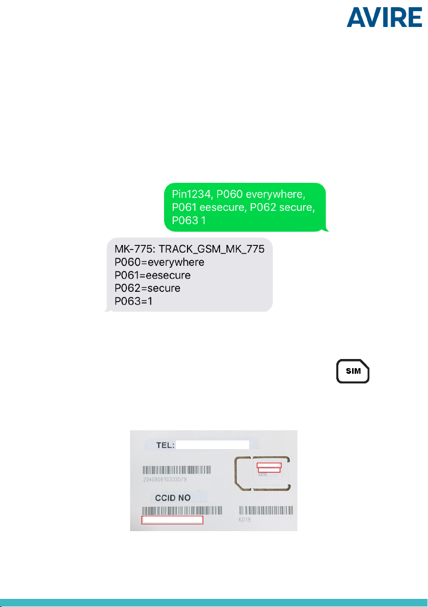
Super settings allow quick and easy conguration of APN settings, depending on the
country and network provider. Using the tables below and on page 4 as an example,
if the country of installation is UK (4), the network provider is EE (3) and the type of
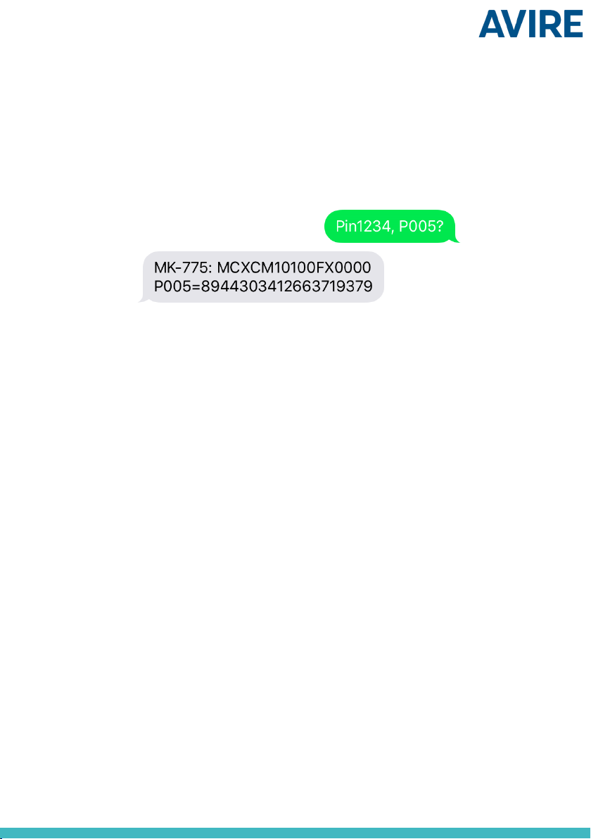
connection is Avire Hub (1), the following text will be sent:
Pin1234, P091 431.
Where Pin1234 is the DCP PIN code, P091 is the command to congure super settings
and 431 is the code for the chosen settings.
The DCP’s default settings are set to 000.
Digit 1 Digit 2 Digit 3
Country Network Type of connection
Digit 1 0-6 7 8
Continent Europe Americas Australasia
OPTION 1 (RECOMMENDED)
You can program the PIN code of the SIM card into the DCP using an analogue phone
plugged into to the J5 connection (please see page 12 for more details).
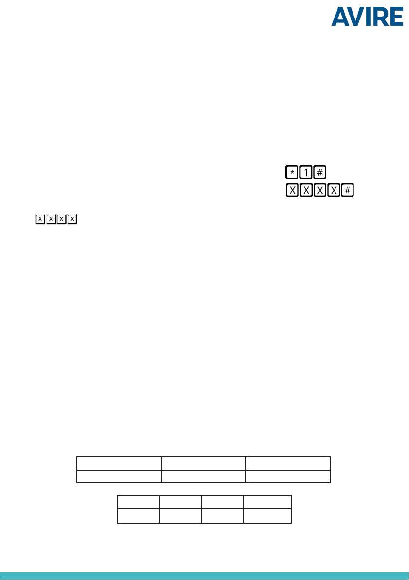
Enter DCP conguration mode and wait for the DCP response:
Enter SIM card PIN parameter:
is the PIN code given by the service provider.
At this point, the SIM card LED (middle LED) will stop ashing red. If it does not, make
sure the SIM is correctly inserted and you have entered the correct PIN.
OPTION 2
Disable the blocking PIN code using a conventional mobile phone. Plug the SIM into a
dierent mobile device and delete SIM PIN code in the device settings.

Digit 2 1 2 3 4 5 6
Spain Portugal Italy UK Germany France
0default default default default default default
1AvireSim AvireSim AvireSim AvireSim AvireSim AvireSim
2Telefonica MEO Wind O2 Telekom DE Orange
3Orange NOS TIM EE ABD SFR
4Vodafone Vodafone Vodafone Vodafone Vodafone DE Bouygues Telecom
5Iliad 3 O2 DE Free Mobile
6tre(3) Virgin BASE
71P Swisscom
8Telit Telit Telit BT A1 Telit
9GiGa tmobileAT
Digit 3 0 1 2 3
Type Transparent Gateway Avire Hub P100 P100 + Avire Hub
4
Once all digits are selected, the text
needs to be sent to the SIM card
telephone number along with the PIN
code and command:
OPTION 2
If non-Avire SIMs are used and their settings are not covered in the table, APN settings
need to be set up manually:
P060 (P zero six zero) APN address
P061 (P zero six one) APN username
P062 (P zero six two) APN password
P063 (P zero six three) Type of connection
These parameters must be congured by sending an SMS to the SIM card number.
Examples for various regional providers are shown below:
Carrier P060 P061 P062
Vodafone UK wap.vodafone.co.uk wap wap
O2 Germany surfo2 (blank) (blank)
Orange France Orange.fr orange orange
P063 0 1 2 3
Type Transparent Gateway Avire Hub P100 P100 + Avire Hub
Other APN settings are available on the web and can be easily found through any
search engine.

Example of an SMS (for example if the SIM card is from Vodafone):
Pin1234, P060 wap.vodafone.co.uk, P061 wap, P062 wap, P063 1
Important Note: The default PIN code for DCP is always 1234.
If either P061 and P062 is (blank) with no username and password provided (O2
Germany example) and the DCP is congured to be used with the Avire Hub, then the
text message will be:
Pin1234, P060 surfo2, P063 1
If everything is congured correctly you will receive a text within a few minutes. The
example below shows the set-up of parameters for EE UK.
OBTAINING THE CCID NUMBER
AVIRE SIM CARDS
Avire SIM cards come precongured to be used with our products
immediately after plugging them in. You will need to know the CCID
number to add this information to the Avire Hub.
The CCID Number is shown on the back of the SIM card and on the outer plastic case
of the SIM card (highlighted in red on the picture below).
5
Important Note: A CCID number consists of 19 digits.

NON-AVIRE SIM CARDS
It is also possible to retrieve the CCID number by sending a SMS command to a SIM
card telephone number; separating the command by a comma as shown below:
Pin1234, P005?
You will receive a text back within a few minutes with the CCID number; in this example
the number shown after “P005=” is the CCID number of this SIM card.
6

AVIRE HUB
Please contact your local sales oce for access to the Avire Hub.
The link to the Avire Hub is https://avirehub.avire-global.com
Please use the “Help” section of the Avire Hub for up-to-date installation tutorials.
Enter information relevant to your installation in General data
7
Click on “Installations” in the menu and
then on “Buildings”. in “Buildings” click on
“Create Building”.

8
On the other side of the page please enter the number of elevator group(s) you have in
this installation and how many elevators you have in the group. As an example, if this is
a simplex installation the number of elevator groups will be “1” and the number of
elevators will be “1”. If it is a duplex installation, it will be “1” and “2”, respectively.
You can also add group names to know which installation is which; once all
information has been entered click “Next”.
In the new page, you should be able to see Groups and Elevators; click on “Add
Gateway” under “Gateway” tab and select “DCP”.
A pop-up window will appear where you can enter the SIM information (Note: Avire
SIMs are (+31), but this doesn’t aect costs).
Enter all required information and then click “Apply”.
Note: The Background Call Period is the frequency of test checks and 72hrs is the
maximum period as per guidance from standards.

Once you’re in, please click on the “Read Parameters” button. On the right-hand side
of the page you will see a window with time, date and the word “Connecting” written
in green. Once the DCP is connected to the Avire Hub parameters will appear, meaning
your DCP is ready to be connected to emergency phones and other products within
our Ecosystem.
9
Click “Save” in the left corner under the General data column.
To make sure everything has been set up correctly click on the green DCP button
again. You should see the new buttons “Access” and “Events” appear.
Click on the “Access” button.

ADDITIONAL INFORMATION FOR PROGRAMMING THE MRL DCP
SMS COMMANDS
+All MRL DCP parameters can be remotely congured via an SMS sent to the SIM card’s number
+Each SMS message should begin with ‘Pin1234’ which is the access code to read or make any changes to the
conguration of the MRL DCP
+You can modify or check several parameters in each SMS by separating them with commas ","
To send parameter information:
Pin1234, Pxxx then value to set, (send)
To read parameter information:
Pin1234, Pxxx? (send)
Note: Use a question mark ‘?’ when you are reading parameters.
Examples:
1. To program telephone number 1 in the MRL DCP when connected to a DAU
E.g. Pin1234, P031 0123456789 (send, text message will come back with P031=0123456789)
2. To retrieve telephone number 1 in the MRL DCP when connected to a DAU
E.g. Pin1234, P031? (send, text message will come back with P031= or with the programmed number)
Note: To reset your unit to default settings the following parameters are important.
CMD Description Default value
P005 CCID- Unique Identier of the Sim Card (19 digits)
P020
MRL DCP Background Call Mode
P020=00 -> Memtel Protocol
P020=06 -> CAN Protocol
P020=21 -> P100 Protocol
21 (Autodiallers need to make
Background calls in P100
Protocol)
P064 Background Call Periodicity (in Minutes) 4320 (3 days)
P031 Alarm Number 1 (Blank – Insert your alarm
number here)
P032 Alarm Number 2 (Blank)
P033 Alarm Number 3 (Blank)
P034 Alarm Number 4 (Blank)
P035 Background Number (not used with DAU)
3308084431 (must match
Background Number in
Autodialler, without prexes)
P008 Enable Guidance Message * 0 (disabled)
P085 Language 4 (English)
P091 Super settings set up 000
P003 MRL DCP information (software version, type of DCP) As per package
Important Note: The default PIN code for DCP is 1234.
10

CONNECTOR DESCRIPTION
Description
J1 Power supply
J2 External antenna
J4 Sim Card
J5 Phone line
J7 CANBus
J8 Serial connector
There is no need to open the cover to
access dipswitches and connectors:
simply plug in and it is ready for use.
J1 - Power Supply
Terminal No. Function Description
1 Gnd Negative for power supply and battery
2 Vin Voltage input from 10 to 30 VDC
3 Battery Separate battery input
The battery works in two ways:
• Buer battery - the supply voltage is battery voltage
• Independent battery - there’s a separate terminal to connect the battery
In both cases the device detects a battery and controls its level of charge.
11
J5

J7 - CANBus
VCC is an unregulated output 10-21 VDC + battery support 10-14 VDC
J2 - External antenna - Connect the external antenna delivered with the kit to the
J2 connector. Only antennas approved by Avire should be used in the installation,
otherwise the device might not function properly and may be damaged.
The device power consumption is 50 mA in standby mode. Each elevator added
requires an extra 20 mA. When the voice call is established consumption is 150 mA plus
an extra 20 mA per elevator. As an example, if four elevators are connected to a device,
the power consumption is 130 mA in standby mode and 230 mA with voice calls.
J5 - Phone Line - High quality analogue phone line which is digitally controlled. Up to
ve extensions can be connected for each elevator group installation. The line voltage
is 48 VDC and the ring signal is 110 VAC and fully senoidal, meaning that any alarm of
any brand can be connected to the device.
J4 - SIM card - The SIM card is required to link the device to the GSM/GPRS net. It
is advisable to disconnect the power supply of the device (including the battery) to
remove or insert the SIM card (although the integrated safety system in the device will
disconnect it automatically).
J8 CONNECTOR - BUS RS-232 or RS-422/485 Serial Connector
The J8 connector is a standard serial communication port that allows the connection of
computers, controls or any other device that needs remote communication through a
reliable wireless data channel. The connectivity provided by the port is in real time and
acts as a point to point transmitter.
Pin Signal Pin Signal
1GND Ground reference 4RX RS232 input
2TX RS232 TX output 5RTS RTS output
3CTS CTS input
Pin Signal Pin Signal
1GND Ground reference 4T- T- RS422
2R+ R+ RS422 (a) 5T+ T+ RS422
3R- R- RS422 (b)
J8 for RS-232:
J8 for RS-485/ RS-422:
(a) T/R+ RS485 half-duplex (b) T/R- RS485 full-duplex
Pin Function Signal
1GND Ground
2CANL Bus CAN L
3CANH Bus CAN H
4VCC Unregulated output + battery
12

LED INDICATORS
The MRL DCP has ve indicator LEDs that constantly report the device status; these will
be either red, amber or green.
Each indicator will be fully on, fully o or ashing. On start-up, you should see the
following within 60 seconds:
RUN LED ashes in green. Power supply is OK
BAT LED is always on Battery is OK
SIM LED is green or amber Device is connected to the network
Coverage LED is green or amber Good coverage
SLIC LED is green Device is in standby
The below tables provide an overview of what each LED colour means:
RUN LED
OFF
ON FLASHING
Green Amber Red Green Amber Red
CRITICAL SYSTEM ERROR Proper
Operation (AC)
Proper
Operation
(BAT)
Restarting
System
BATTERY
OFF
ON FLASHING
Green Amber Red Red
OK Charging Low Error
SIM OFF ON Flashing
Green Amber Red Green Amber Red
AT
modem
Available
GSM and
GPRS
GSM
available
GPRS not
available
Out of
Service /
Initialising
Ongoing Data
Transmission
Ongoing
voice call
Sim error or
missing pin
Amber/Red Missing PUK
COVERAGE
OFF
ON
Green Amber Red
AT
modem OK Medium Low
SLIC
OFF
ON Flashing
Green Amber Red Green
RS-232 local
conguration
Local line
ready
Initialising
local line
Local line
out of
service
Local line in use
13

BATTERY BACKUP
AC-ABD10-100-0-00-000
START GUIDE
The backup battery can be purchased separately and works alongside the MRL DCP to
power it in case of mains power failure. The Battery Backup is mounted on the DIN rail
next to the MRL DCP and connected using the pre-wired cable loom provided with the
Battery Backup.
The battery comes pre-set to o. To turn the battery on turn the switch to the left when
the label is on the top.
Switch currently in
the “on” position
The mains to Battery Backup and Battery Backup to MRL DCP connections should not
exceed 2m to comply with EMC standards.
14

WIRING
INPUT
The Battery Backup has an input with two pins available to connect to.
The voltage mains input is used to power the MRL DCP and charge the Battery Backup;
it is driven by an external 12-30VDC supply with input current of 1A at max.
OUTPUT
The Battery Backup has an output with three pins available to connect to.
Pin Function Signal Wiring colour
1 GND Ground Brown
2 Vout Voltage out White
3 Batt. Battery output Green
Pin Function Signal
1 GND Ground
2 Vin Voltage in
15
Ground
Ground
Voltage In
Voltage Out
Battery Voltage

LED INDICATOR
LED State Voltage Mains Battery Operating State
Flash every second Present Present The battery is charging. The mains connection is
powering the MRL DCP.
Solid Present Present The battery is fully charged. The mains connection is
powering the MRL DCP.
Flash every 32 seconds Not present Present Battery Backup is in low power mode and no longer
powers the MRL DCP.
Solid Present Present The battery is faulty and needs to be replaced.
Flash every second Not present Present The battery is discharging as it powers the MRL DCP.
Solid Present Not present The battery is not connected and mains connection
powers the MRL DCP.
The inbuilt sensor periodically checks the quality and the capability of the battery;
during this check the LED on the device ashes rapidly for 15-30 seconds.
When removing the Battery Backup from the DIN rail please take extra care; connectors
need to be removed and a screwdriver used to lever the clips from the rail.
ADDITIONAL INFORMATION
In case of an old battery, the battery replacement can be purchased separately.
Product Number Product Description
MK999RE020-B1 Battery Kit
16
Please read the label on the Battery Backup device for the recommended battery
expiry date. The battery provided is a 3.6V 650mA Ni-Mh type, widely recommended
for 2 to 3 years of use.
LED indicator

ENVIRONMENT CONDITIONS
This device is designed to be used indoors (0oC to 45oC with relative humidity between
20% to 80% not condensing). Sudden changes of temperature and humidity should be
avoided.
CLEANING AND MAINTENANCE
Use a soft dry cloth. Do not use solvent or abrasive products.
SAFETY
Please read these safety instructions before starting the device.
+Do not expose this device to liquids or excessive humidity. The DCP is an indoor device and
is not waterproof
+Do not expose the device to re
+Do not try to modify the device
+Do not use the device in potentially hazardous areas or where there is risk of explosion
The DCP emits low levels of radio frequency when in operation.
DISPOSAL
The device complies with regulations 2002/95/CE and 2003/108/CE regarding
the use and disposal of hazardous substances in electric appliances.
Do not dispose of this device with unsorted household waste. Disposing
of the device in an unauthorised way could result in a ne in line with local
regulations.
ENVIRONMENTAL REGULATIONS
RoHS - Avire certies that its production process complies with the 2002/95/CE
European Directive of 27 January 2003 regarding the restriction of use of hazardous
substances in electric and electronic appliances.
MRL DCP&BOB IG_V01 (GB): PC 10/12/2019
Avire Trading Ltd
Unit 1, The Switchback
Gardner Road
Maidenhead
Berkshire
SL6 7RJ, UK
T: 01628 540100
F: 01628 621 947
E: sales.uk@avire-global.com
W: www.avire-global.com

MRL DCP
Installationsanleitung
Ref No MU-875X0AV10A-DE Version 1
AC-2CD00-100-F-20-000
PRODUKTBESCHREIBUNG
Die maschinenraumlose (MRL) digitale Kommunikationsplattform DCP wird im Inneren der
maschinenraumlosen Steuerung installiert und stellt ein Informationsgateway zwischen allen kompatiblen
angeschlossenen Geräten im Aufzugsschacht und unserer Online-Überwachungsplattform (Avire Hub
bereit.
Die MRL DCP verfügt über einen eingebauten Scanner für die Mobilfunksignalstärke, um den Signalpegel
an dem vorgesehenen Installationsort zu messen.
Sie können die MRL DCP als Duplex-Datenverbindung für die folgenden Zwecke verwenden:
- Kongurieren und Überwachen von Geräten über MK CAN-Bus und Avire Hub
- Prüfen von Aufzügen aus der Ferne über Verbindung zu Lift HAWK
- Überwachung von Panachrome+ Lichtgittern
- Aktualisierung von Display-Layouts
- Anbindung von Notrufsystemen nach EN 81-28:2018
ZUR INSTALLATION ERFORDERLICHE MITTEL
Im Lieferumfang enthalten – MRL
DCP
+ MRL DCP
+ Stecker P-3.5 H-2V (x1)
+ Stecker P-3.5 H-3V (x1)
+ Stecker P-3.5 H-4V (x1)
+ Stecker P-3.5 H-5V (x1)
+ Benutzerhandbuch
Im Lieferumfang enthalten –
Notstrombatterie
+ Notstrombatterie
+ Stecker P-3.5 H-3V (x1)
+ Stecker P-5 BL2 (x1)
+ Kabel
Nicht im Lieferumfang enthalten
+ Schraubendreher
+ DIN-Schiene (prüfen, ob
in der Aufzugssteuerung
Steckplätze für MRL DCP und
Notstrombatterie verfügbar
sind)

AUFZUGSICHERHEIT
Hinweis: Alle Gesundheits- und Sicherheitsvorschriften müssen eingehalten und alle
notwendigen Vorsichtsmaßnahmen vor der Installation getroen werden.
EINRICHTEN DER MRL DCP
Avire SIM-Karten werden im aktivierten und einbaufertigen Zustand geliefert.
Wenn eine SIM-Karte verwendet wird, die nicht von Avire stammt, aktivieren Sie
diese bitte vor der Installation und erkundigen Sie sich beim SIM-Anbieter, wie dabei
vorzugehen ist.
1. Setzen Sie die SIM-Karte in Steckplatz J4 ein, und drücken Sie auf die SIM-Karte, bis
sie einrastet.
2. Schließen Sie die Antenne an Anschluss J2 der
MRL DCP an, und stellen Sie sicher, dass sie
vollständig eingeschraubt ist.
HINWEIS: Verwenden Sie nur Antennen, die von
Avire freigegeben sind.
1
*Eine vollständige Darstellung sowie Informationen zu Anschlüssen nden Sie auf den Seiten 11
und 12.
J4*
J2*
Sie können den Status der Stromversorgung, der Batterie, der Verbindung, der
Netzabdeckung oder der Teilnehmeranschluss-Schnittstellenschaltung (SLIC)
jederzeit anhand der LED-Anzeigen (Seite 13) überprüfen.
3. Schließen Sie die Stromversorgung (zwischen 10 VDC und 30 VDC)
über den im Lieferumfang enthaltenen 3-poligen Stecker an J1 an,
oder schließen Sie das Gerät an die Notstrombatterie an (separat
erhältlich, siehe Seite 14 zur Einrichtung).
4. Stellen Sie sicher, dass die Betriebs-LED ( ) grün blinkt (dies
dauert maximal 60 Sekunden). Wenn die SIM-LED ( ) rot blinkt,
stellen Sie sicher, dass die SIM-Karte ordnungsgemäß eingesetzt
wurde und dass SIM-Karten, die nicht von Avire stammen, per PIN
entsperrt sind (siehe Seite 3, „Entsperren der SIM-Karte“).
J1*
Table of contents
Languages: