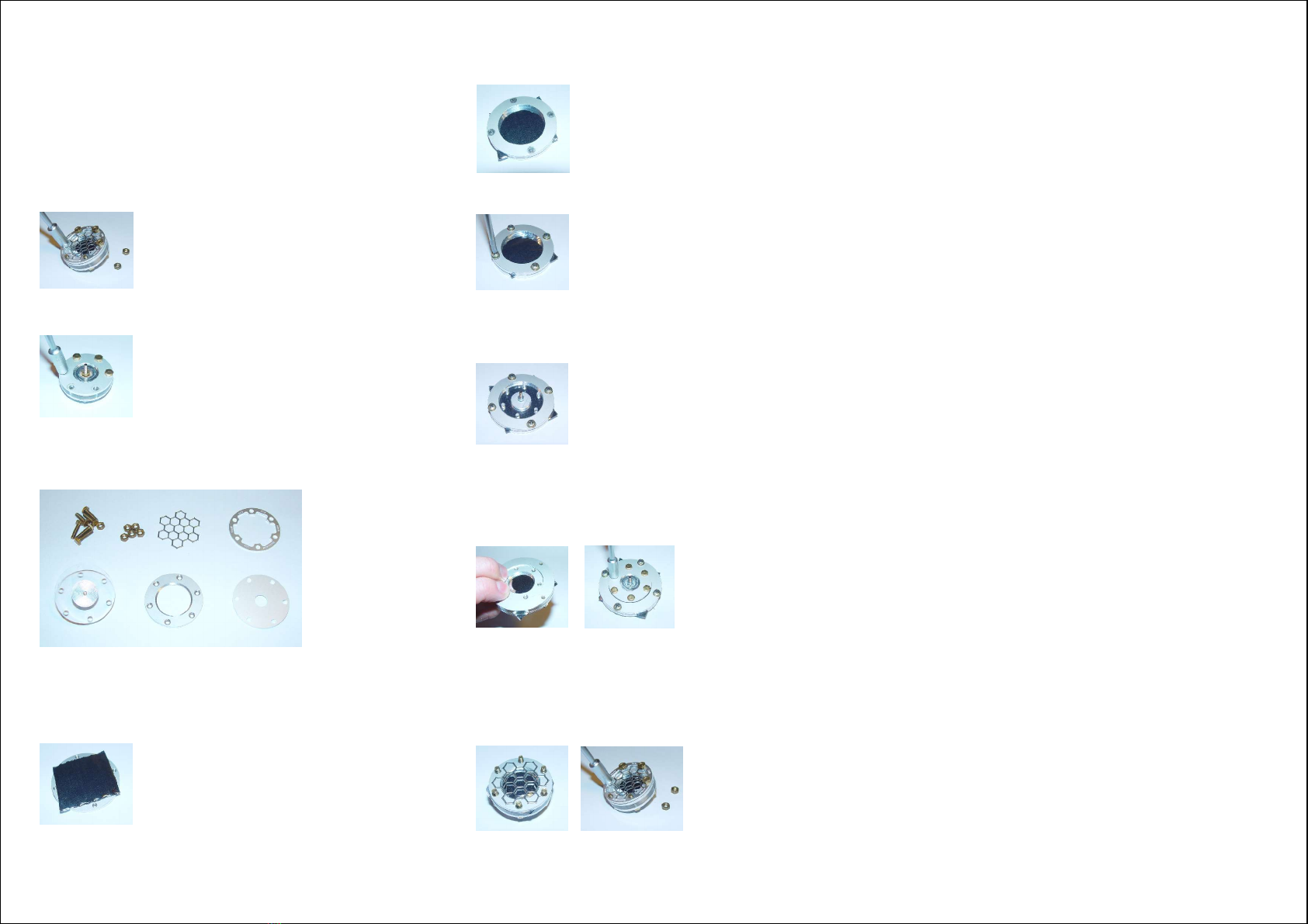
Condenser Microphone Capsule CM16
The microphone capsule consists of a thin metalized polyester film
and a metal back plate. Do not touch the diaphragm because its
metalization could be destroyed. It is recommended to use the
capsule always with the protective grid. However, depending on the
grid type, the frequency response may be degraded in some way.
Therefore, it is possible to remove or replace the grid by releasing
the nuts on the front side use the supplied 5.5 mm box spanner).
Due to its thin metalization, the diaphragm may deteriorate
especially under humid conditions. Therefore, it is recommended to
store the microphone in a dry place. Spare capsules are available
on request and deteriorated diaphragms will be replaced by Avisoft
Bioacoustics at a small fee. With some skill, it would also be
possible to replace the membrane foil on your own by releasing the
screws on the back of the capsule).
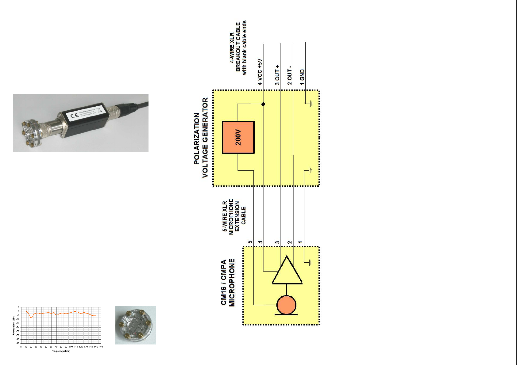
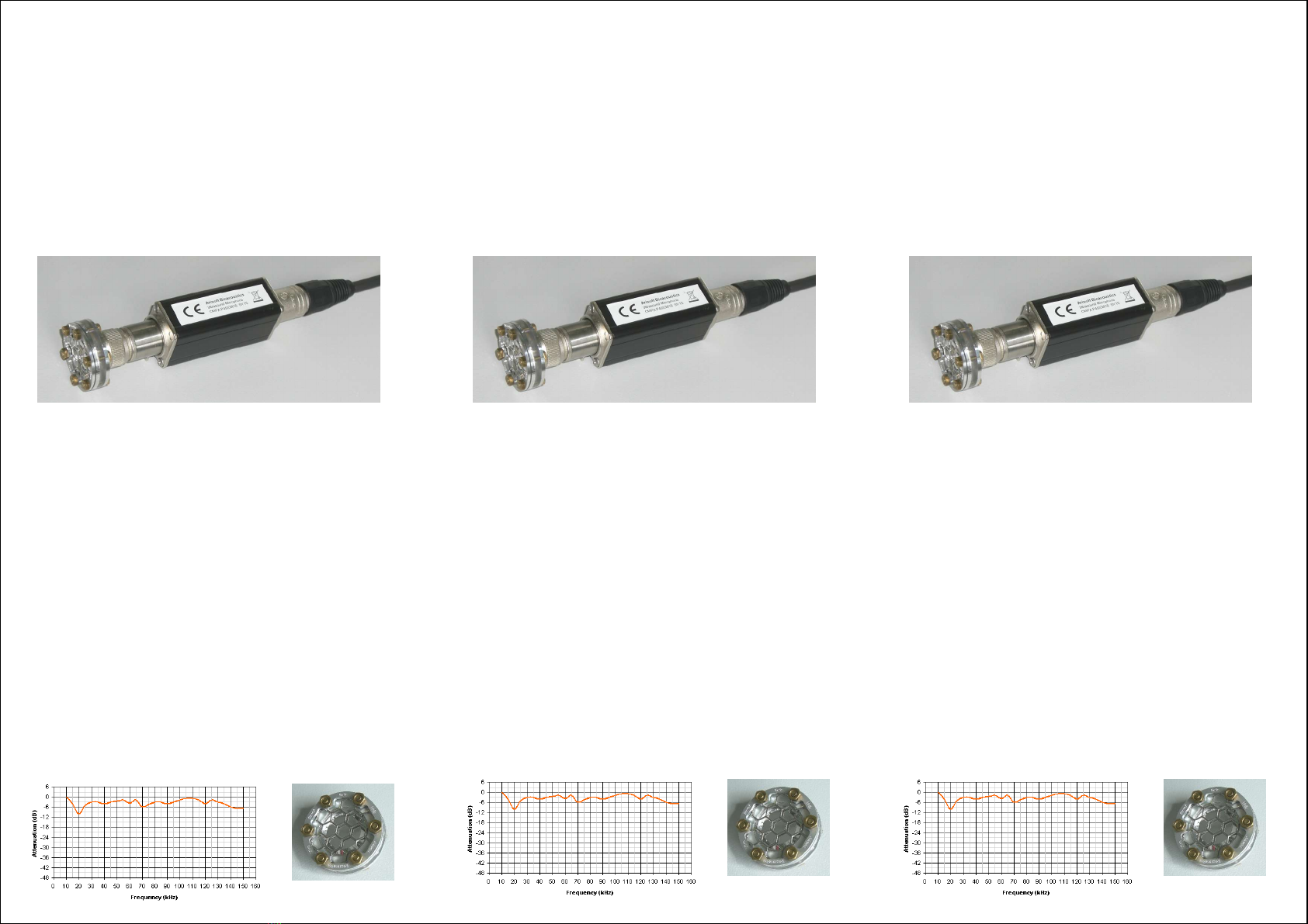
The condenser microphone CMPA-P48/CM16 consists of three
components. The microphone capsule CM16 #1) is connected to
the cylindric preamplifier module CMPA #2) by means of a 2.5 mm
thread. This allows to replace the capsule easily. For proper
operation, both this 2.5 mm thread and the 17 mm thread on the
preamplifier module must be fastened. However, use only moderate
forces in order to prevent mechanical damages. The P48
polarization voltage supply unit #3) provides the polarization voltage
for the microphone capsule and the XLR-3 connector that allows to
connect the microphone to a standard microphone input that
supplies P48 phantom power at a current of up to 10mA . The CMPA
module #2) can be attached either directly to the polarization
module #3) or via the supplied 5-pole XLR extension cable.
The integrated preamplifier has an internal compensation circuit that
slightly boosts frequencies above 50 kHz.
Condenser Microphone CM16/CMPA-P48
2
1
3
Condenser Microphone Capsule CM16
The microphone capsule consists of a thin metalized polyester film
and a metal back plate. Do not touch the diaphragm because its
metalization could be destroyed. It is recommended to use the
capsule always with the protective grid. However, depending on the
grid type, the frequency response may be degraded in some way.
Therefore, it is possible to remove or replace the grid by releasing
the nuts on the front side use the supplied 5.5 mm box spanner).
Due to its thin metalization, the diaphragm may deteriorate
especially under humid conditions. Therefore, it is recommended to
store the microphone in a dry place. Spare capsules are available
on request and deteriorated diaphragms will be replaced by Avisoft
Bioacoustics at a small fee. With some skill, it would also be
possible to replace the membrane foil on your own by releasing the
screws on the back of the capsule).
The condenser microphone CMPA-P48/CM16 consists of three
components. The microphone capsule CM16 #1) is connected to
the cylindric preamplifier module CMPA #2) by means of a 2.5 mm
thread. This allows to replace the capsule easily. For proper
operation, both this 2.5 mm thread and the 17 mm thread on the
preamplifier module must be fastened. However, use only moderate
forces in order to prevent mechanical damages. The P48
polarization voltage supply unit #3) provides the polarization voltage
for the microphone capsule and the XLR-3 connector that allows to
connect the microphone to a standard microphone input that
supplies P48 phantom power at a current of up to 10mA . The CMPA
module #2) can be attached either directly to the polarization
module #3) or via the supplied 5-pole XLR extension cable.
The integrated preamplifier has an internal compensation circuit that
slightly boosts frequencies above 50 kHz.
Condenser Microphone CM16/CMPA-P48
2
1
3