Avizia MX200 Manual

Extended Height Cart for Cisco MX200/MX300
USER AND INSTALLATION GUIDE
Extended Height Cart | User & Installation Guide
© 2013 Avizia Inc. All rights reserved. | aviziatech.com | AVZ-MXC-DOC-UIG-04
1

Table of Contents
Important Safety Instructions ...other resources including 3
Safety Precautions....................................................................3
Cautions .....................................................................................3
Warnings..................................................................................... 3
Cart Overview ................................................................................4
Features and Benefits ..............................................................4
Tools and Parts for Installation ..................................................5
Assembly and Installation...........................................................6
Cart Assembly............................................................................ 6
Cable Installation......................................................................7
Display Installation | MX200....................................................8
Display Installation | MX300....................................................9
Cable Plugin.............................................................................11
Storage Shelf Installation......................................................12
Cable Cover Installation........................................................13
Adjusting Cart Height .................................................................14
Cart Use and Maintenance........................................................15
What’s in this guide?
For more information about configuring and using your
Avizia product, refer to the following URL:
http://aviziatech.com/support.html
where you can find a video showing step by step installa-
tion and other resources.
Extended Height Cart | User & Installation Guide
© 2013 Avizia Inc. All rights reserved. | aviziatech.com | AVZ-MXC-DOC-UIG-04
2

Important Safety Instructions
SAFETY PRECAUTIONS, CAUTIONS, AND WARNINGS
Safety Precautions
Failure to read, thoroughly understand, and follow all
instructions can result in serious personal injury, damage to
equipment, or voiding of factory warranty! It is the installer’s
responsibility to make sure all components are properly as-
sembled and installed using the instructions provided.
Use this mounting system only for its intended use as
described in these instructions. Do not use attachments not
recommended by the manufacturer.
Never operate this mounting system if it is damaged.
Return a damaged mounting system to a service center for
examination and repair.
Cautions
This caution symbol means be aware and pay
attention as you work on any equipment.
Warnings
This warning symbol means danger. You are in
a situation that could cause bodily injury.
Before you work on any equipment, be aware
of the hazards involved with electrical circuitry
and be familiar with standard practices for preventing
accidents. Statement 1071
SAVE THESE INSTRUCTIONS.
RISK OF INJURY TO PERSONS! Do not place video equipment
such as televisions or computer monitors on storage shelf
surface!
Exceeding the weight capacity can result in serious personal
injury or damage to equipment! The combined weight of all
components stored within or on the storage shelf cannot
exceed 25 lbs (11.3 kg).
Extended Height Cart | User & Installation Guide
© 2013 Avizia Inc. All rights reserved. | aviziatech.com | AVZ-MXC-DOC-UIG-04
3

Cart Overview
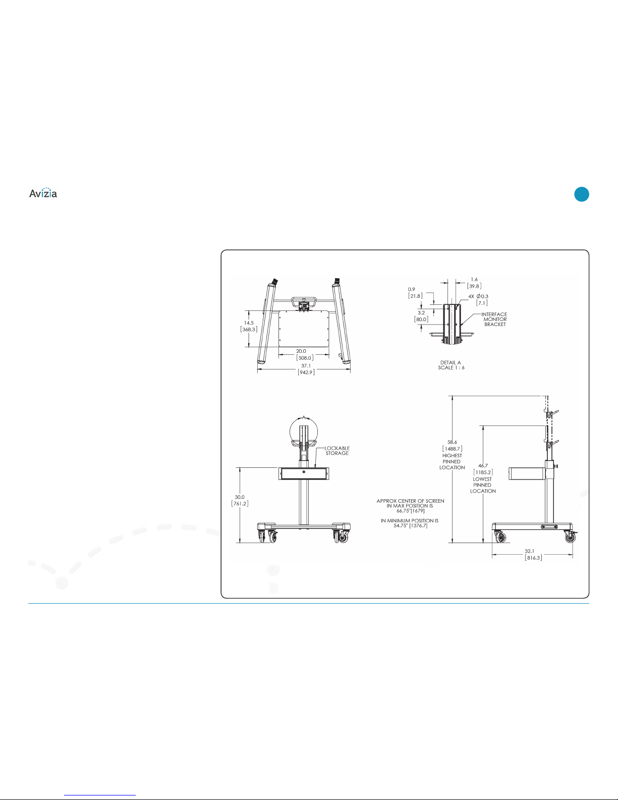
CART OVERVIEW AND DIMENSIONS
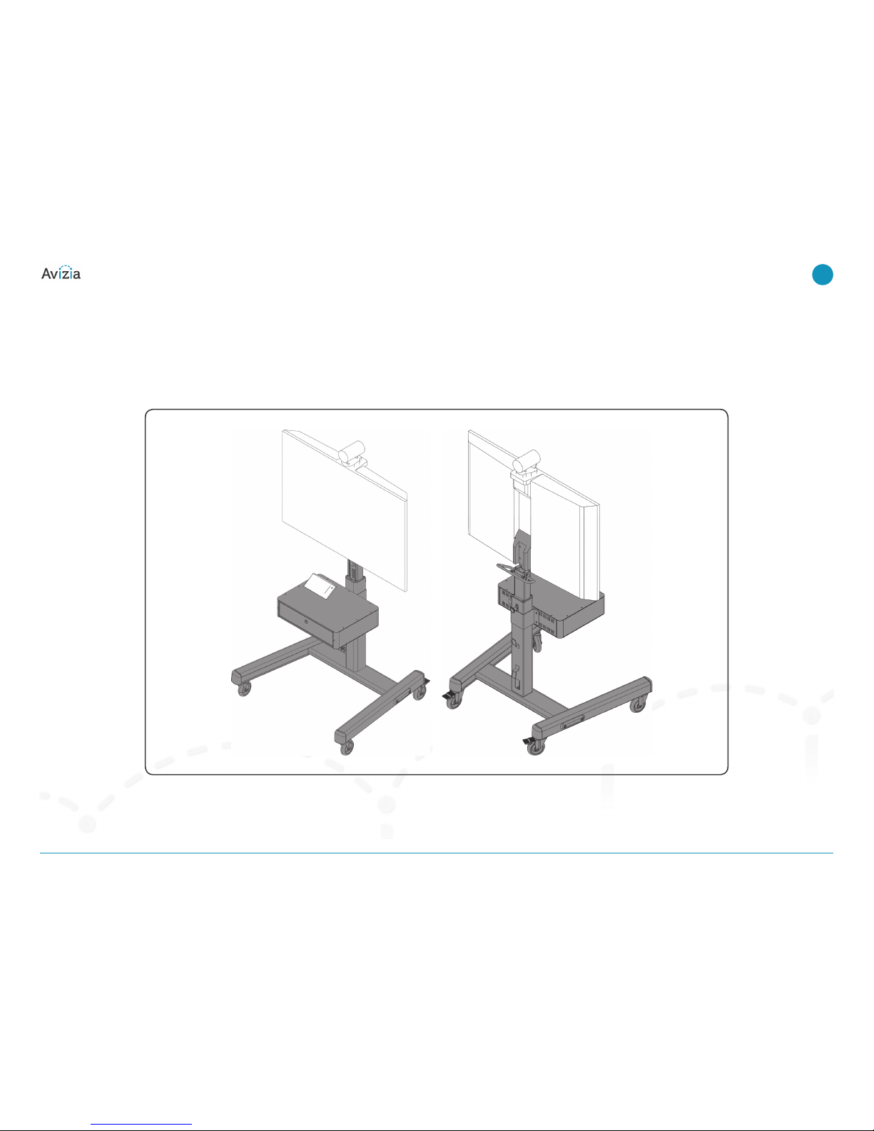
The Avizia Extended Height Cart for the Cisco MX200/MX300
is designed to transform the way people learn and the way
instructors present material in a collaborative, geographically
distributed environment. With the advent of Cisco
TelePresence conferencing, many organizations have realized
the advantages of maintaining a virtual learning environment
with a remote site, while still being able to collaborate using
high-quality presentations.
The unique design of this versatile system helps ensure
stability while easily transporting the system throughout
commercial and educational institutions. The extended
height of the display is well suited for classroom
environments, enabling participants seated toward the back
of the room to view the display.
Features and Benefits
• Integrated column mounting hardware for the MX200 or
MX300 helps ensure stability and differentiation with no
VESA mount required.
• A gas assist-lift cylinder allows for easy height adjustment
from 52.84 inches (1342.14 mm) to 60.84 inches (1545.34
mm), helping ensure that students in the back of a
classroom can participate in the videoconference.
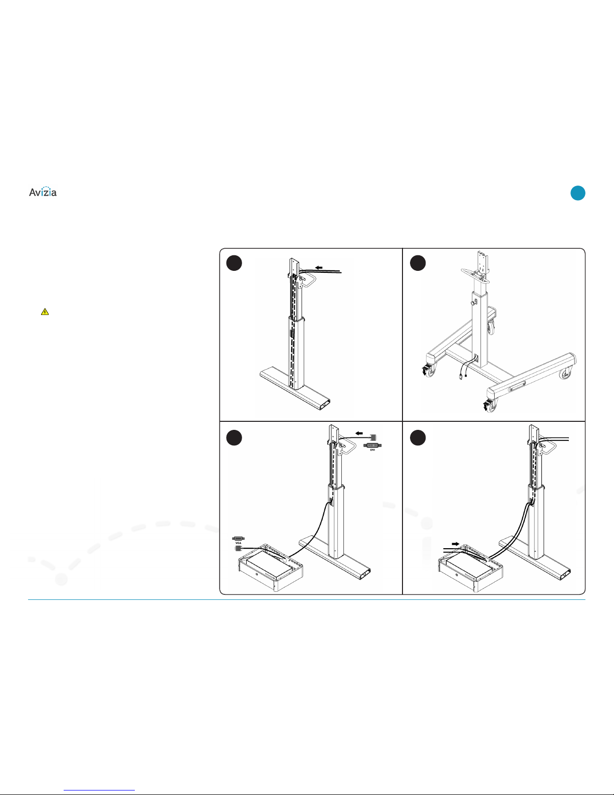
• Egress holes in the column simplify cable management.
• A lockable storage shelf secures the Cisco TelePresence
Touch interface, microphone, and XGA cable.
• The cart has heavy-duty 7-inch premium casters with a
rear locking mechanism.
Extended Height Cart | User & Installation Guide
© 2013 Avizia Inc. All rights reserved. | aviziatech.com | AVZ-MXC-DOC-UIG-04
4

Tools and Parts for Installation
Phillips Screwdriver
(not included)
Tighten Fastener
By Hand
Loosen Fastener
Hex Head Wrench
Adjust
Phillips Screwdriver
Extended Height Cart | User & Installation Guide
© 2013 Avizia Inc. All rights reserved. | aviziatech.com | AVZ-MXC-DOC-UIG-04
5

Assembly and Installation
Cart Assembly
CAUTION: Attachment holes may be damaged if a power
drill is used to insert button head cap screws. Screws should
first be inserted and turned BY HAND with the hex key or with
a handheld screwdriver BEFORE using a hex head drill bit and
power drill (optional) to complete the attachment.
1. Assemble two legs (A and B) to the column assembly (D)
using two 5/16-18 x 4-1/4” button head cap screws (E)
and one end cap (C) per leg.
NOTE: When attaching the legs, make sure the larger
holes are on the outside and the smaller holes on the
inside and locking casters are to the rear of the cart.
CAUTION: The INNER COLUMN of the Column Assembly
IS SHIPPED DISENGAGED and may pinch hands! Hold both
inner and outer posts (columns) while removing from box.
1(E) x 4
(A) x 1
(B) x 1
(D)
(C) x 2
Cable
Management
Egress
Locking Wheels x 2
Cart Handle
locking knob for
height adjust-
ment
Extended Height Cart | User & Installation Guide
© 2013 Avizia Inc. All rights reserved. | aviziatech.com | AVZ-MXC-DOC-UIG-04
6

Assembly and Installation
Cable Installation
1. Starting from the back of the column, the display power
cord and network cable can be run through the cutout
towards the top of the post and down through the front
of the post.
WARNING: Ensure that the cables are running down
the front side of the post covered by the rubber cable
sleeves as opposed to the back of the post that houses
the gas cylinder locking pin.
2. Once the display power cord and network cable are at
the bottom of the post, pull the cords out through the
back egress towards the base of the post. Pulling the
cords out from the right side of the gas cylinder is easiest.
3. Run the content sharing (DVI to VGA) cable through the
cutout towards the top of the post starting with the VGA
end of the cable. Then run the cable down the front
of the post covered by the rubber cable sleeves,out
through the egress in the front middle of the post, and
through the back cutout of the storage shelf which will
be installed in a later step.
4. Route cables from the touchpanel and microphones
through the storage shelf, out the back cutout of the
storage shelf, through the cutout on the front middle of
the post, up the post (staying behind the rubber cable
sleeves), and out through the cutout towards the top of
the post.
1 2
3 4
Touchpanel
and micro-
phone cables
Power and
Ethernet
cables
Extended Height Cart | User & Installation Guide
© 2013 Avizia Inc. All rights reserved. | aviziatech.com | AVZ-MXC-DOC-UIG-04
7

Assembly and Installation
Display Installation | MX200
This cart has been designed
specifically for the Cisco
Telepresence MX200 or MX300
flat panel displays. It is not
recommended that any other
display be used to mount on this
cart.
For MX300 installation proceed to
page 8, DISPLAY INSTALLATION |
MX300.
CAUTION: Before attaching display to cart, set the brakes
on the back wheels by pressing down on the tabs to prevent
instability that could result in possible injury.
1. Carefully slide display onto column assembly (D).
WARNING: Two people are required to lift the
chassis. To prevent injury, keep your back straight and
lift with your legs, not your back. Statement 164
2. Hand tighten two M6x40mm socket head cap screws (J)
into the top two holes on display and interface plate.
3. Hand tighten two M6x40mm socket head cap screws (J)
into the bottom two holes on display and interface plate.
4. Tighten all four screws using Hex Key.
5. Proceed to page 10, STORAGE SHELF INSTALLATION.
1
Apply Brakes
(D)
Extended Height Cart | User & Installation Guide
© 2013 Avizia Inc. All rights reserved. | aviziatech.com | AVZ-MXC-DOC-UIG-04
8

Assembly and Installation
Display Installation | MX300
This cart has been designed
specifically for the Cisco
Telepresence MX200 or MX300
flat panel display. It is not
recommended that any other
display be used to mount on this
cart.
CAUTION: Before attaching display to cart, set the brakes
on the back wheels by pressing down on the tabs to prevent
instability that could result in possible injury.
1. Remove MX200 BACK COVER BRACKET from the column
assembly (D) by removing two screws and washers.
2. Reuse screws and washers from Step 1 to secure the
MX300 BACK COVER BRACKET (P) to column assembly.
3. Use #10-24 x 1/2” Phillips pan machine screw (N) and
#10-24 wing nut (Q) to secure MX300 CLIP to column
assembly’s interface plate.
Apply Brakes
MX300 back cover bracket
MX300 CLIP
(continued on next page)
Extended Height Cart | User & Installation Guide
© 2013 Avizia Inc. All rights reserved. | aviziatech.com | AVZ-MXC-DOC-UIG-04
9

Assembly and Installation
Display Installation | MX300
4. Carefully slide display onto column assembly (D).
WARNING: Two people are required to lift the
chassis. To prevent injury, keep your back straight and
lift with your legs, not your back. Statement 164
5. Hand tighten two M6x50mm socket head cap screws
(K) into the top two holes on the display interface plate.
NOTE: Top screws must be installed first in order to
ensure interface holes are properly aligned with the
display.
6. Hand tighten two M6x60mm socket head cap screws (L)
into the lower two holes on the display interface plate.
7. Tighten top screws with Hex Key.
8. Tighten the lower screws screws with Hex Key.
9. Proceed to page 10, STORAGE SHELF INSTALLATION.
MX300 DISPLAY
Extended Height Cart | User & Installation Guide
© 2013 Avizia Inc. All rights reserved. | aviziatech.com | AVZ-MXC-DOC-UIG-04
10

Assembly and Installation
Cable Plugin
1. Plug all of the cables routed through the post in previous
steps into their respective plugs on the back of the MX
unit including: power, ethernet, DVI content sharing with
associated audio, touchpanel, and microphone(s).
1
Extended Height Cart | User & Installation Guide
© 2013 Avizia Inc. All rights reserved. | aviziatech.com | AVZ-MXC-DOC-UIG-04
11

Assembly and Installation
Storage Shelf Installation
1. Use four 1/4-20 x 3/4” button head cap screws (H) to
secure pole attachment plate (G) to storage shelf (F).
NOTE: Pull the slack between the column and the shelf out
of the cables running through the storage shelf as the shelf is
moved towards the column.
WARNING: Exceeding the weight capacity can result in
serious personal injury or damage to equipment! The
combined weight of all components stored within or on the
storage shelf cannot exceed 25 lbs (11.3 kg). Statement 398
1(H) x 4
(F)
(G)
Cable
Management
Egress
Extended Height Cart | User & Installation Guide
© 2013 Avizia Inc. All rights reserved. | aviziatech.com | AVZ-MXC-DOC-UIG-04
12

Assembly and Installation
Cable Cover Installation
1. Place two tabs on underside of MX200/MX300 back cover
(included with display) into two holes on bracket on back
of column assembly. This bracket is located just above
the cart handle.
NOTE: MX200 aluminum cable cover used to complete cart
installation is included with the Cisco TelePresence MX200 42
Table Stand Option, Cisco part number CTS-MX200-42-TSK,
which should be ordered with the MX200 per the datasheet
instructions. Appearance of MX200 aluminum cable cover may
vary from the illustration.
NOTE: MX300 cable cover used to complete cart installation
is included with the Cisco TelePresence MX300 55 Wall Mount
Option, Cisco part number CTS-MX300-55-WMK, which should
be ordered with the MX300 per the datasheet instructions.
Appearance of the MX300 cable cover may vary from the
illustration.
2. Install the back cover of the MX200/MX300 onto the back
of the display by pushing it into position until it snaps
into place.
NOTE: If cable cover does not fit securely in Step 2,
adjust height of cable cover bracket with the following
procedure:
a. Loosen screws holding back cover bracket to column
assembly.
b. Adjust back cover bracket height up or down until
Cisco back cover fits securely.
c. Tighten screws holding back cover bracket to column
assembly.
tabs at
bottom of
cover
Extended Height Cart | User & Installation Guide
© 2013 Avizia Inc. All rights reserved. | aviziatech.com | AVZ-MXC-DOC-UIG-04
13

Adjusting Cart Height
NOTE: The column assembly contains a gas spring which
allows for safe and easy height adjustment after the display
has been mounted. Adjusting the height when the display is
not attached is much more difficult and not recommended.
1. Pull out knob on the column assembly and turn 90° in
either direction to disengage the locking mechanism.
2. Raise or lower the display using the back handle.
3. Turn the knob 90° either direction to engage the knob
and lock the cart at desired height.
NOTE: Set the height of the cart so the display does NOT
rest on the lower part of the center post. Always set the
height so the knob is engaged in a hole in the center
post.
back handle
locking knob for height
adjustment
1
2
Do NOT let the display
rest here; always engage
the locking knob in a
hole along the adjust-
able post.
3
Extended Height Cart | User & Installation Guide
© 2013 Avizia Inc. All rights reserved. | aviziatech.com | AVZ-MXC-DOC-UIG-04
14

Cart Use and Maintenance
CAUTION: This cart is intended for use only with the
products and maximum weights indicated. Use with other
products or products heavier than the maximum weights
indicated may result in instability causing possible injury.
CAUTION: Cart can tip over resulting in risk of injury and
damage to the system. Move cart slowly. Apply moving force
on narrow dimension. Never apply force at top - always push
or pull with handle.
1. Always place cart on level surface.
2. Always lock the wheels when the cart is not moving.
3. When moving the cart, push or pull the by the cart’s
handle.
4. Use the cable wrap on column to hang cables as needed
when moving cart.
push or pull cart
with handle
cable wrap
Do NOT push cart near the
top of the system.
2
3
4
1
Extended Height Cart | User & Installation Guide
© 2013 Avizia Inc. All rights reserved. | aviziatech.com | AVZ-MXC-DOC-UIG-04
15

THE SPECIFICATIONS AND INFORMATION REGARDING THE PRODUCTS IN THIS MANUAL ARE SUBJECT TO CHANGE WITHOUT NOTICE. ALL
STATEMENTS, INFORMATION, AND RECOMMENDATIONS IN THIS MANUAL ARE BELIEVED TO BE ACCURATE BUT ARE PRESENTED WITHOUT
WARRANTY OF ANY KIND, EXPRESS OR IMPLIED. USERS MUST TAKE FULL RESPONSIBILITY FOR THEIR APPLICATION OF ANY PRODUCTS.
THE SOFTWARE LICENSE AND LIMITED WARRANTY FOR THE ACCOMPANYING PRODUCT ARE SET FORTH IN THE INFORMATION PACKET THAT
SHIPPED WITH THE PRODUCT AND ARE INCORPORATED HEREIN BY THIS REFERENCE. IF YOU ARE UNABLE TO LOCATE THE SOFTWARE LICENSE OR
LIMITED WARRANTY, CONTACT YOUR AVIZIA REPRESENTATIVE FOR A COPY.
NOTWITHSTANDING ANY OTHER WARRANTY HEREIN, ALL DOCUMENT FILES AND SOFTWARE OF THESE SUPPLIERS ARE PROVIDED “AS IS” WITH
ALL FAULTS. AVIZIA AND THE ABOVE-NAMED SUPPLIERS DISCLAIM ALL WARRANTIES, EXPRESSED OR IMPLIED, INCLUDING, WITHOUT LIMITATION,
THOSE OF MERCHANTABILITY, FITNESS FOR A PARTICULAR PURPOSE AND NONINFRINGEMENT OR ARISING FROM A COURSE OF DEALING, USAGE,
OR TRADE PRACTICE.
IN NO EVENT SHALL AVIZIA OR ITS SUPPLIERS BE LIABLE FOR ANY INDIRECT, SPECIAL, CONSEQUENTIAL, OR INCIDENTAL DAMAGES, INCLUDING,
WITHOUT LIMITATION, LOST PROFITS OR LOSS OR DAMAGE TO DATA ARISING OUT OF THE USE OR INABILITY TO USE THIS MANUAL, EVEN IF AVIZIA
OR ITS SUPPLIERS HAVE BEEN ADVISED OF THE POSSIBILITY OF SUCH DAMAGES.
Avizia and the Avizia Logo are trademarks of Avizia, Inc. and/or its affiliates in the U.S. and other countries. Third party trademarks mentioned
are the property of their respective owners. The use of the word partner does not imply a partnership relationship between Avizia and any other
company.
Any Internet Protocol (IP) addresses and phone numbers used in this document are not intended to be actual addresses and phone numbers. Any
examples, command display output, network topology diagrams, and other figures included in the document are shown for illustrative purposes
only. Any use of actual IP addresses or phone numbers in illustrative content is unintentional and coincidental.
MX Series Guides and Regulatory Compliance and Safety Information Guide:
http://www.cisco.com/en/US/partner/products/ps11776/prod_installation_guides_list.html
Extended Height Cart | User & Installation Guide
© 2013 Avizia Inc. All rights reserved. | aviziatech.com | AVZ-MXC-DOC-UIG-04
16
8800-002470 Rev 00
This manual suits for next models
2
Table of contents