TECNICOMAR MINIMAR PLUS User manual

Instructions for the installation, use and maintenance of Tecnicomar watermaker
1-1
INSTRUCTIONS FOR THE INSTALLATION, USE AND MAINTENANCE OF
TECNICOMAR WATERMAKERS
Models
MINIMAR PLUS
SAILOR
BICOMPACT
NOTE
The indications contained in this Manual must be strictly followed during installation, operation and
maintenance of the watermaker in order to warrant the operators' safety and the equipment
maximum efficiency.
Identification
The Tecnicomar watermaker carries a plate with the following data:
a) Manufacturer: TECNICOMAR SpA, C/da Berbaro n.145/D –91025 Marsala –ITALY –
Tel.0923-969409 / Fax 0923-960235;
b) CE logo;
c) Type
d) Serial number
e) Year of manufacture
f) Voltage
Revision
1
2009
Revision
2
07/2011
Revision
3
03/2012
Revision
4
03/2013
Revision
5
12/2014
Revision
6
08/2015
CONTROL BOX TINY2 DESCRIPTION UPDATED

Instructions for the installation, use and maintenance of Tecnicomar watermaker
1-2
Dear Customer,
We would like to thank you for choosing a TECNICOMAR WATERMAKER.
This watermaker has been designed by expert technicians and manufactured with care for all its
aspects and in respect of the European standards.
Our widespread commercial organization guarantees accurate and prompt assistance and
maintenance service to our Customers.
This Manual provides the User with the illustrated, step-by-step instructions on how to install and
use the watermaker. It also contains all the necessary information for the maintenance.
WARNING !
TECNICOMAR S.p.A. declines any and all liability for failure to observe the safety and
accident prevention standards described in this manual, for damage dued to the improper
use of the equipment and for modifying it without the authorization of Tecnicomar S.p.A.
Contents of the Instruction Manual:
Section 1 contains information for storage before unpacking.
Section 2 contains the process description and system components identification.
Section 3 contains information about installation.
Section 4 contains information about first start-up procedure.
Section 5 contains information about routine operation.
Section 6 contains the emergency operation and the long period shutdown information.
Section 7 contains maintenance and setting instruction of the safety components.
Section 8 contains useful troubleshooting information.
Section 9 contains the technical characteristics of the equipment.
Signs used throughout the Manual
Warning
These instructions should be followed carefully to operate the watermaker correctly.
Danger
These instructions should be followed carefully to avoid damage to the watermaker or
to the operator.
Note or Information
The notes contain important information and useful hints for the watermaker
operation.
If not specified otherwise, letters used in the text refer to the functional diagram shown in the
drawings situated at the end of this Manual.
* * * * * * * * * * * *
This Manual is intellectual property of Tecnicomar S.p.A. Any reproduction of contents or
drawings –unless authorized by Tecnicomar S.p.A. –is not permitted and will be prosecuted.
©Tecnicomar

Instructions for the installation, use and maintenance of Tecnicomar watermaker
1-3
TABLE OF CONTENTS
1Storage prior to unpacking and packaging content............................................................................................1-6
1.1 Storage prior to unpacking..............................................................................................................................1-6
1.2 Checking packaging content............................................................................................................................1-6
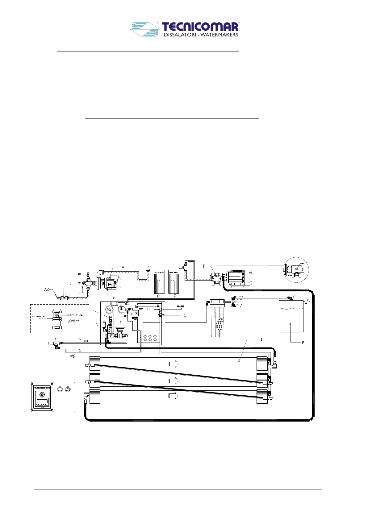
2Process description and system components identification................................................................................2-9
3Installation Procedure.........................................................................................................................................3-11
3.1 Components supplied by owner .....................................................................................................................3-11
3.2 Plumbing connections....................................................................................................................................3-11
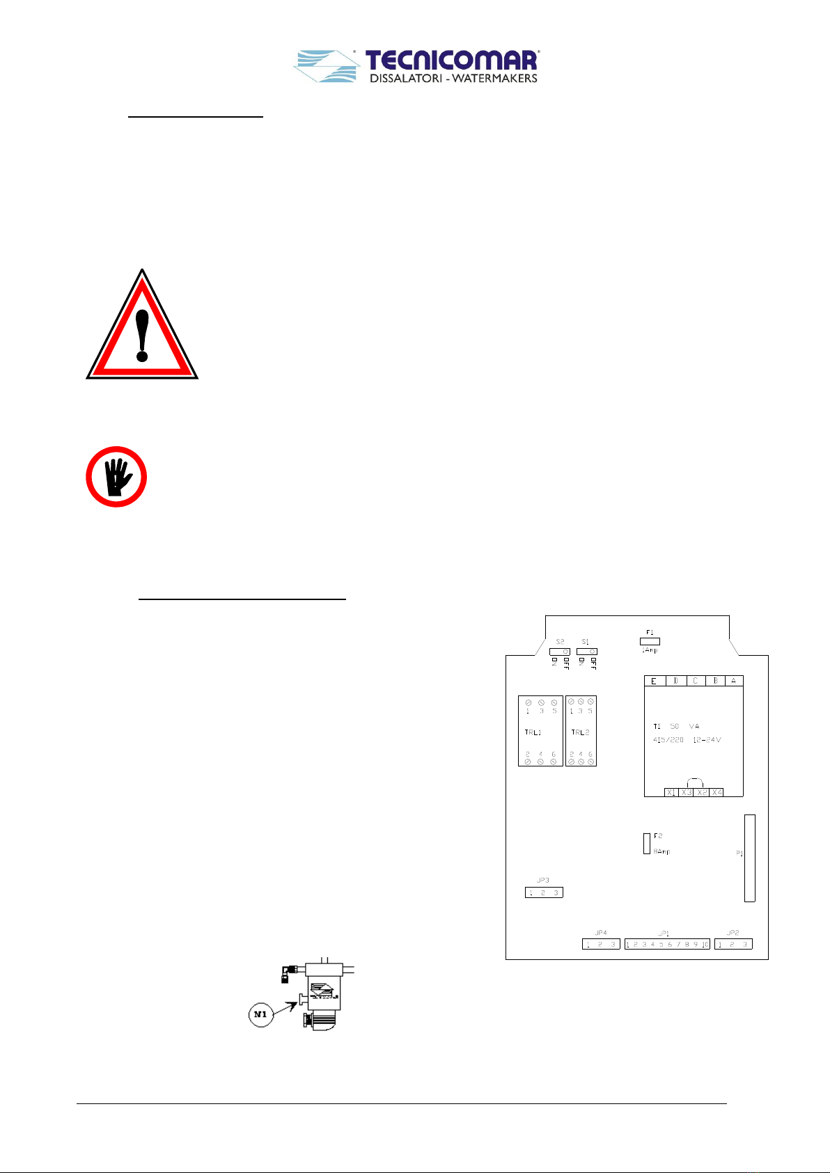
3.3 Power connection ..........................................................................................................................................3-12
4First Start-up procedure .....................................................................................................................................4-15
4.1 Shut down procedure .....................................................................................................................................4-16
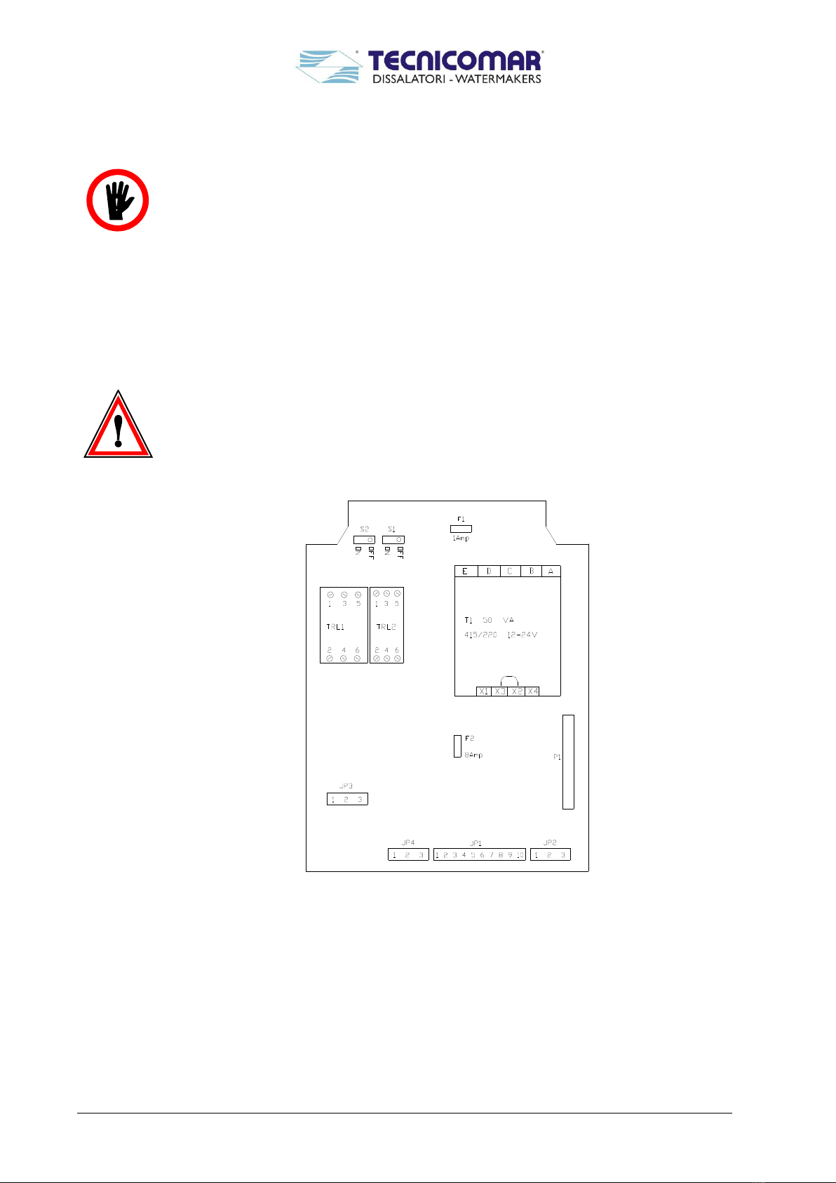
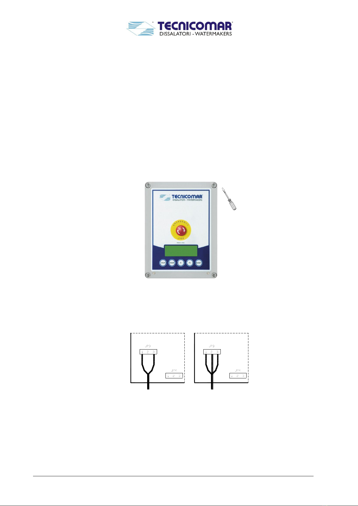
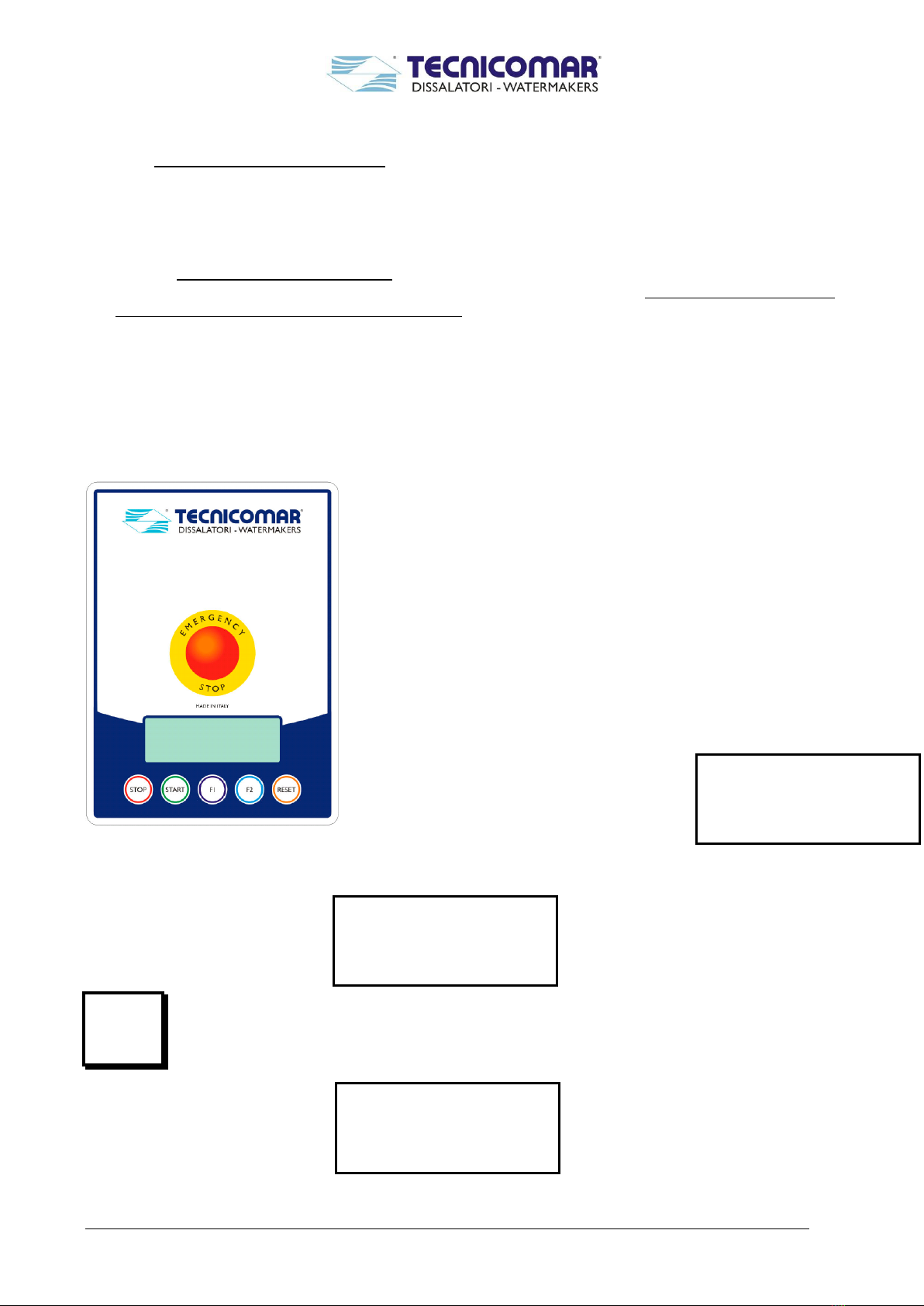
4.2 TINY 2 microprocessor control box. Description and operation...................................................................4-16
5Routine operation ................................................................................................................................................5-18
5.1 Routine operation (c/w automatic pressure regulator device).......................................................................5-18
5.2 Routine operation (c/w manual pressure regulator device)...........................................................................5-18
5.3 Manual running mode (c/w automatic pressure regulator device)................................................................5-19
5.4 Operation in low- or high-salinity areas .......................................................................................................5-19
5.5 Operation in cold areas.................................................................................................................................5-19
6Special procedures...............................................................................................................................................6-20
6.1 System normal operation. ..............................................................................................................................6-20
6.2 Emergency operation.....................................................................................................................................6-20
6.3 Preservation of membrane modules in very cold areas.................................................................................6-22
6.4 Optionals........................................................................................................................................................6-22
6.4.1 Automatic flushing system ....................................................................................................................6-22
6.4.2 Remote control.......................................................................................................................................6-23
6.4.3 Touch screen..........................................................................................................................................6-23
6.4.4 UV sterilizer...........................................................................................................................................6-23
6.4.5 Multimedia sand filter or TFD filter ......................................................................................................6-23
7Maintenance.........................................................................................................................................................7-24
7.1 Ordinary Maintenance...................................................................................................................................7-24
7.1.1 Preservation and care of the semipermeable membrane modules..........................................................7-24
7.1.2 High-pressure circuit..............................................................................................................................7-24
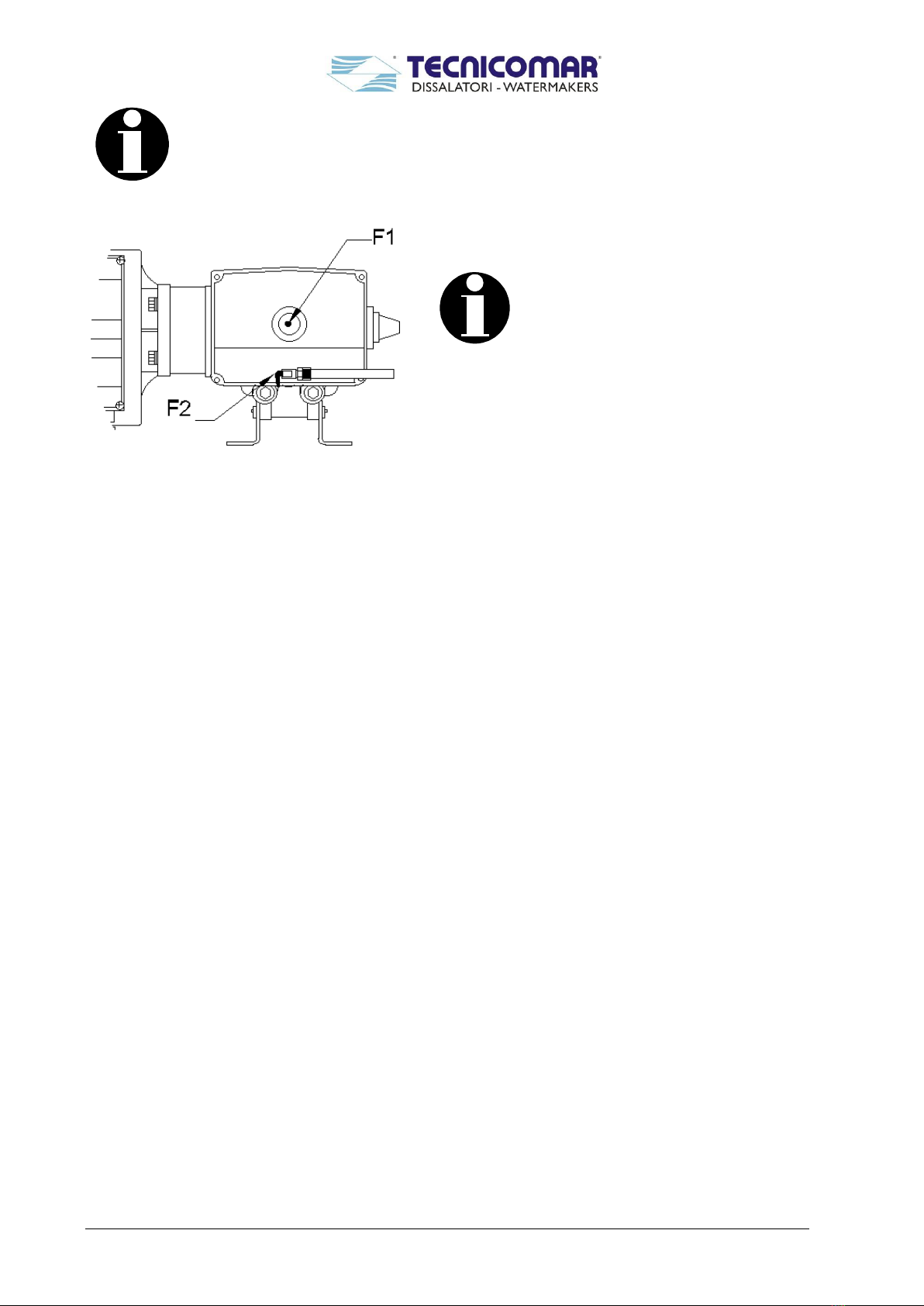
7.1.3 Oil changing in the CAT high-pressure pump .......................................................................................7-24
7.1.4 Prefilters maintenance............................................................................................................................7-25
7.1.5 Carbon filter replacement ......................................................................................................................7-25
7.2 Extraordinary maintenance ...........................................................................................................................7-26
7.2.1 Replacement of membrane modules......................................................................................................7-26
7.2.2 Salinity and temperature sensors (M+M1).............................................................................................7-26
7.3 Long-period shut down procedure.................................................................................................................7-26
7.3.1 In case of automatic pressure regulator device ......................................................................................7-26
7.3.2 In case of manual pressure regulator device ..........................................................................................7-27

Instructions for the installation, use and maintenance of Tecnicomar watermaker
1-4
7.4 Membrane flushing with FL/411A and FL/412B chemicals ..........................................................................7-28
7.5 General maintenance plan.............................................................................................................................7-29
7.5.1 Prefiltering circuit..................................................................................................................................7-29
7.5.2 Pressurizing circuit ................................................................................................................................7-29
7.5.3 Controls and produced water circuits.....................................................................................................7-29
7.6 Maintenance kit..............................................................................................................................................7-29
8Common problems and troubleshooting ...........................................................................................................8-31
8.1 First start-up..................................................................................................................................................8-31
8.2 Start-up after the replacement of filter cartridges .........................................................................................8-31
8.3 Low pressure failure......................................................................................................................................8-31
8.4 Low pressure failure during normal operation..............................................................................................8-31
8.5 Operation with vessel in navigation, rough sea and LOW PRESSURE alarm on .........................................8-31
8.6 Normal operation of the watermaker and overload failure shutdown...........................................................8-32
8.7 UNSAFE warning message during normal operation ...................................................................................8-32
8.8 The watermaker runs normally but the produced water does not reach the tanks ........................................8-32
9Technical characteristics and spare parts .........................................................................................................9-33
9.1 Electrophysical characteristics......................................................................................................................9-33
9.2 A typical analysis of produced water.............................................................................................................9-33
9.3 Spare part list ................................................................................................................................................9-34
9.3.1 High pressure pump...............................................................................................................................9-34
9.3.2 Other spare parts....................................................................................................................................9-34
9.4 Warranty for Tecnicomar equipments ...........................................................................................................9-41
Annexes
DRAWINGS
Drawing 1 FLOW DIAGRAM
Drawing 2 CLEANING/STORAGE
Drawing 3 WIRING DIAGRAM
Drawing 4 AUTOMATIC PRESSURE REGULATOR
Drawing 5 ELECTR. CONNECTIONS
Drawing 6 AUTOMATIC FLUSHING SYSTEM
Drawing 7 PRESSURE VESSEL
HIGH PRESSURE PUMP (Parts list –exploded view)
LOW PRESSURE PUMP (Parts list –exploded view)
Test certificate

Instructions for the installation, use and maintenance of Tecnicomar watermaker
1-5
What is Reverse Osmosis
Osmosis is the diffusion of two mixable solutions through a semipermeable membrane in such a
manner to equalize their concentration. A water with less salt naturally diffuses into a water with
higher salt.
Sea water or brackish water cannot naturally diffuse through a semipermeable membrane to
provide potable water.
A man-made process, REVERSE OSMOSIS, overcomes this natural phenomenon. By forcing
sea or brackish water (under high pressure) through a semipermeable membrane, potable water can
be realized !

Instructions for the installation, use and maintenance of Tecnicomar watermaker
1-6
1Storage prior to unpacking and packaging content
1.1 Storage prior to unpacking
Do not store in direct sunlight.
Do not freeze (see paragraph 6.3).
Do not store above 50°C (122°F).
Store only on base with arrows up.
1.2 Checking packaging content
In the package there are the following components:
SAILOR (compact version)
SAILOR (slim version)

Instructions for the installation, use and maintenance of Tecnicomar watermaker
1-7
SAILOR (modular version)

Instructions for the installation, use and maintenance of Tecnicomar watermaker
1-8
MINIMAR PLUS (compact version)
Installation kit
Clamps - Manual - Tank connection fitting - Inlet hose - Filters wrench - Discharge and Fresh water
hoses - Discharge fitting

Instructions for the installation, use and maintenance of Tecnicomar watermaker
2-9
2Process description and system components identification
The watermaker has four main sections:
Prefiltration section where salt water, supplied by the booster pump (A), is filtrated passing through the two
prefilters (B and C). Feed water pressure is taken by the low pressure sensor (E) and shown on the display of the
electric box (Lbar);
High pressure section in which sea water is pressurized by the high-pressure pump (F). The high-pressure sensor
(G), electrically connected to the electric box, shuts down the system automatically if the operating pressure exceeds
the preset level. The unit can be equipped with automatic pressure regulator valve (I) or can be run also in manual
mode and the working pressure adjusted manually by the pressure regulator valve (I) located on top of the
motorized valve. The high-pressure tubes and their fittings require periodic (see MAINTENANCE section).
Salt water (BRINE) discharge section. In this section the brine is discharged. The fresh water is also discharged out
of board if it does not have the drinking-water quality. Through the three-way solenoid valve (N), the electric box
automatically switches the water coming from membranes either to the discharge or to the fresh water tank. The
water quality is checked by the salinity sensor (M). The temperature sensor (M1) compensates the reading
according to temperature. The salinity and temperature sensor require periodic maintenance (see MAINTENANCE
section).
Freshwater section. This is the most important section of the system, the section where the physical process of
reverse osmosis takes place. The main components of this section are the semipermeable membranes which separate
sea water in two flows: one with concentrated salts which goes to the discharge (R) and the other with fresh water
(U) which goes to the fresh water tank. The fresh water flow is taken by the flow sensor (L) before reaching the
three-way solenoid valve (N) and shown on the display. The three-way solenoid valve (N) switches the flow,
depending on its salinity, to the discharge or to the tank. The semipermeable membranes are very sensitive
components and require strict observance and care (see PROTECTION AND CARE OF SEMIPERMEABLE
MEMBRANES in Maintenance section).
Flow diagram (in case of supply c/w automatic pressure regulator)-see also attached drawing-
DISSALATORI-WATERMAKERS

Instructions for the installation, use and maintenance of Tecnicomar watermaker
2-10
Flow diagram (in case of supply c/w manual pressure regulator) -see also attached drawing-
DISSALATORI-WATERMAKERS

Instructions for the installation, use and maintenance of Tecnicomar watermaker
3-11
3Installation Procedure
3.1 Components supplied by owner
Some plumbing and electric components are to be supplied by owner. These components are listed below:
a) 3/4" or 1” inlet valve with terminal (A2, drawing 1);
b) Tank for produced water (P). The tank should have a safety overflow valve (V1);
c) 3/4" female thread discharge to the sea. A discharge fitting of 3/4 female (Y) is supplied by Tecnicomar where lines
BRINE (R) and UNSAFE WATER (S) are connected (refer to drawing 1);
In case of installation aboard a vessel, the discharge must be installed above the water line.
d) power supply line, protected by an automatic all-pole thermal and differential protection/ disconnection device. The
differential circuit breaker must be set to act with the dissipation current of 30 mA. For setting of the thermal circuit
breaker and for the sizing of the power supply line the values from the POWER REQUIREMENT TABLE should
be respected (ref. Section 9).
3.2 Plumbing connections
CONSIDERATIONS:
Lenght of connection lines: the watermaker will work most efficientely with short plumbing connections. When the
suction line is long the feed pressure decreases. When the discharge line is long the back pressure increases in that
line. There should be no back pressure on the discharge line or on the product line.
Feed water: be sure that the inlet thru-hull fitting is installed in a way that the watermaker receives an uninterrupted
supply of air-free feed water.
Membranes: the membrane vessels must not be exposed to temperature higher than 50°C (122°F) or lower than 5°C
(41°F). For preservation of membrane modules in very cold areas see par. 6.3
For correct installation of SAILOR in compact and modular version:
Connect the SEA WATER INLET (A2) with the T1 side of the manual three-way valve (T) using the supplied hose
of dia. 20 mm.
Connect the outlet of the low pressure pump (A) with the inlet of the prefilters (B).
Connect the Auto-Flushing system (if supplied) to the tee fitting on the prefilters.
Connect the BRINE (R) and UNSFE WATER (S) lines to the discharge connector (Y).
Install the supplied fresh water fitting (V) onto the fresh water tank (P). Connect outlet of three-way solenoid valve
(U line) to the fresh water fitting (V). Be sure that fresh water tank has an overflow valve (V1).
For correct installation of SAILOR in splitted (slim) version (control panel, membranes module, low pressure pump
and prefilters):
Connect the SEA WATER INLET (A2) with the T1 side of the manual three-way valve (T) on the low pressure
pump using the supplied hose of dia. 20 mm.
Connect the outlet of the low pressure pump (A) with the inlet of the prefilters (B).
Connect the Auto-Flushing system (if supplied) to the tee fitting on the prefilters.
Connect outlet of prefilter (C) to inlet of the high pressure pump (F) and to the low pressure gauge (D).
Connect the outlet of the high pressure pump (F) to the first membrane.
Connect the dischrge from membranes to the pressure regulation valve (I) located behind the control panel.
Connect the produced water from mebranes to the flowmeter (L)
Connect the BRINE (R) and UNSFE WATER (S) lines to the discharge connector (Y).
Install the supplied fresh water fitting (V) onto the fresh water tank (P). Connect outlet of three-way solenoid valve
(U line) to the fresh water fitting (V). Be sure that fresh water tank has an overflow valve (V1).
Be sure to tighten well gaskets and fittings to avoid air infiltration or water leaks.

Instructions for the installation, use and maintenance of Tecnicomar watermaker
3-12
3.3 Power connection
Unscrew the four plastic bolts on the front panel of the electric box and lift the cover (Fig. 2).
When opening the electric box front panel, do not pull on the cable bunch connecting it to the box
itself. Do not pull the leads as they might break (refer to the Fig. 1).
MAKE SURE THAT THE POWER SUPPLY IS OFF AND THAT NOBODY CAN SWITCH IT
ON DURING THIS OPERATION.
Connect the power supply line to the electric control box. Use terminals Nos. 1 and 3 if the watermaker is single-
phase type (refer to the id plate on the watermaker motors and main frame) and terminals Nos. 1, 2 and 3 for the
three-phase systems (fig.3).
Close the electric box cover by tightening well the four bolts on its front (Fig. 2).
Connect the watermaker steel structure to the ground using the grounding lug identified by the appropriate symbol
(the point is on the steel structure or in the control panel).
Power on the supply line and check that the display is illuminated.
WARNING - Do not press the START key before having done the first start-up procedure
(section 4).
Figure 1 - inside of the electric box

Instructions for the installation, use and maintenance of Tecnicomar watermaker
3-13
Figure 2 –control box
Figure 3
Single-phase power supply connection
Three -phase power supply connection

Instructions for the installation, use and maintenance of Tecnicomar watermaker
3-14
ONLY FOR CAT PUMP
Be sure that the high pressure pump (F) has enough oil for correct operation. The correct oil level
must reach the red point on the glass bezel (F1) in the rear of the pump. Use the valve (F2) to
change oil (refer to the MAINTENANCE section). Remove the sticker from the pump oil plug
ONLY FOR CAT PUMP
To ensure good lubrication the PUMP must
be installed in an horizontal base. Use oil
supplied by Tecnicomar only!
Figure 4 - oil valve and level mark on CAT pump

Instructions for the installation, use and maintenance of Tecnicomar watermaker
4-15
4First Start-up procedure
Before the first start-up it is necessary to check that no component of the system was damaged during transport or
handling; this is especially important for the high-pressure circuit components.
If all steps for the correct installation of the watermaker have been followed (Section 3), the first start-up procedure can
be done:
Be sure that all electrical connections are correctly made.
Open the filters (B) and (C) and fill them with pure non-chlorinated water. Check that filter cartridges are inside.
Re-install the filters.
Open the inlet valve (A2).
Make sure that manual three-way valve (T) is on position T1 (operation).
Open the valves along the discharge line, if installed.
Open the valve on the fresh water tank, if installed.
Switch on the power supply and check that the display is on.
If there is three-phase power supply, press F1 to start the feeding pump
and, from the motor fan side, control the clockwise rotation (opposite the
sense indicated in the pump body).
Push STOP.
Switch on the feeding pump by F1 and operate for 5-10 minutes,
controlling that:
Salty water is discharged (BRINE)
Low pressure gauge indicates steadily over 1 bar.
If there aren’t this two conditions the feeding pump is not correctly primed ( i.e. problems in installation: feeding
pump above the sea cock valve, air inside the system, …), therefore is not allowed to start the high pressure pump.
Push STOP.
Remove the sticker from the high pressure pump cap (F).
Check that the EMERGENCY STOP push-button is not activated (turn clock-wise).
Start the system by pressing START.
If the unit is equipped with a motorized valve to auto-regulate the pressure, we recommend to run and stop the unit
ONLY by the START and STOP keypads. If by chance you have pushed the EMERGENCY STOP red button, we
recommend to unlock the button by turning it counter-clockwise but NOT TO RUN immediately the unit. WAIT AT
LEAST 2 MINUTES BEFORE PUSHING START. This is to prevent the unit from starting when the valve is still
closed and the plant is pressurized which can damage SERIOUSLY the membranes and the motor.
If after about 20 seconds the feed water pressure does not rise, the system shuts down automatically.
WARNING - Do not repeat the start-up more than twice if the system does not start.
Check that no air is sucked in and that there are no water leaks in the whole system.
In case of automatic pressure regulator device
After some minutes of operation, the system pressure (Hbar) gradually increases up to 60 bar. Check the pressure
for a few minutes. If there are any leaks, stop the system by pressing the STOP key. Correct the problem and start
the system again by repeating the above procedure.
In case of manual pressure regulator device
After at least 5 minutes of operation, gradually increase the system pressure by slowly turning the pressure control
valve (I) clockwise. Keep doing it until the reading of the high pressure on the display is 60 bar (850 psi). Check the
pressure for a few minutes. If there are any leaks, stop the system by pressing the STOP key. Correct the problem
and start the system again by repeating the above procedure.
Never operate the watermaker at a pressure exceeding 60 bar (850 PSI)
As soon as the system is pressurized the production of fresh water begins and is monitored by the electronic salinity
control system which will automatically switch the flow to the tank when it is desalinated.
Feeding Pump

Instructions for the installation, use and maintenance of Tecnicomar watermaker
4-16
4.1 Shut down procedure
In case of automatic pressure regulator device
Push STOP.
After the de-pressurizing phase the system stops.
Switch off the power supply.
Close the sea water inlet valve (A2).
In case of manual pressure regulator device
Depressurize the system by turning the pressure control valve (I) counterclockwise (ignore this point if the unit is
equipped with the automatic pressure regulator device).
Push the STOP key on the electric box.
Switch off the power supply.
Close the sea water inlet valve (A2).
4.2 TINY 2 microprocessor control box. Description and operation
Hereafter are described the operation modalities and functions of the different keys on the front panel:
The alphanumeric display can show the following information:
HObar = high pressure
HIbar = high pressure (if the unit is equipped also with a sensor
before the membranes)
Lbar = low pressure
T = water temperature
L/m = lt/minute of product water
LP = total product water since last starting
H = hours/minutes of running
AMP = System electrical consumption in Amps
SAL = product water salinity (microsiemens/cm)
AVV = start counter
When the system is in stand-by the display shows the following:
The STOP key allows to switch-off the watermaker. When the system is running the display shows the following:
The START key allows to start the watermaker. When the system is ON push it to show the start-counter
(AVV) and the product water LP (liter/minute) readings (see picture below).
START
HObar=0 Lm=0.0
Lbar=0.08 SAL=88
T=15.3 °C AMP=0.0
SYSTEM RUNNING
HObar=0 L/m=0.0
Lbar=0.08 SAL=88
T=15.3 °C AMP=0.0
LP=0.0 AVV=0
HObar=0 H=0.00
Lbar=0.08 SAL=88
T=15.3 °C AMP=0.0
SYSTEM STAND-BY

Instructions for the installation, use and maintenance of Tecnicomar watermaker
4-17
When the system is OFF, by holding this key for 4 seconds is possible to start only the low pressure
pump (A). This function is useful to backwash the Sand Filter (if the model installed is with manual
valves) or to circulate the membranes cleaning chemicals.
When the system is OFF, this key can start the automatic membrane flushing system - if installed - (push
for 4 seconds). When the “ lamp change” warning appears, this key allows to cancel it (push for 4 sec.).
When a failure occurs the RESET key allows to switch-off the acoustic alarm and to reset the control
box.
WARNINGS ON THE DISPLAY
Unsafe Water
The unit is producing unsafe water that is being discharged outboard.
VISUAL and SOUND ALARMS
High Pressure
The unit stops for high working pressure. Push RESET to re-start it. Check section 8 “Troubleshooting” for possible
causes.
Low Pressure
The unit stops for low working pressure. Push RESET to re-start it. Check section 8 “Troubleshooting” for possible
causes.
Overload
The unit stops for overload. Push RESET to re-start it. Check section 8 “Troubleshooting” for possible causes.
F1
F2
RESET

Instructions for the installation, use and maintenance of Tecnicomar watermaker
5-18
5Routine operation
5.1 Routine operation (c/w automatic pressure regulator device)
After having carried out the first start-up (section 4), the everyday start-up and operation of the watermaker will be
simple and fast.
Follow the START-UP steps listed below:
Open the sea water inlet valve (A2).
Start up the system by pressing START.
Check that the feed water pressure is correct: the low pressure value showed on the display should not get below
30% of the reading as it was with new filter cartridges. If necessary, clean or replace the filter cartridges. The
electric box will automatically shut down the system if the feed water pressure is below the minimum level needed
for the correct operation (0.3 bar).
Prefiltrated, clean sea water is extremely important for correct operation of the watermaker. It is
also a good help to longer life of membranes. We recommend the exclusive use of replacement
cartridges supplied by Tecnicomar.
If the produced water salinity increases, contact the Tecnicomar Service center.
Follow the SHUT DOWN steps for a correct and safe system power-off:
Push STOP.
Switch off the power supply.
Close the sea water inlet (A2).
5.2 Routine operation (c/w manual pressure regulator device)
After having carried out the first start-up (section 4), the everyday start-up and operation of the watermaker will be
simple and fast.
Follow the START-UP steps listed below:
Open the sea water inlet valve (A2).
Make sure that the pressure control valve (I) is open (ignore this point if the unit is equipped with the automatic
pressure regulator device).
Start up the system by pressing START.
Check that the feed water pressure is correct: the low pressure value showed on the display should not get below
30% of the reading as it was with new filter cartridges. If necessary, clean or replace the filter cartridges. The
electric box will automatically shut down the system if the feed water pressure is below the minimum level needed
for the correct operation (0.3 bar).
Prefiltrated, clean sea water is extremmely important for correct operation of the watermaker. It is
also a good help to longer life of membranes. We recommend the exclusive use of replacement
cartridges supplied by Tecnicomar.
Apply gradually the operating pressure (850 psi = 60 bar) by slowly turning the pressure control valve (I)
clockwise (ignore this point if the unit is equipped with the automatic pressure regulator device).
Check that after a few minutes of operation the UNSAFE warning disappears.

Instructions for the installation, use and maintenance of Tecnicomar watermaker
5-19
If the produced water salinity increases, contact the Tecnicomar Service center.
Follow the SHUT DOWN steps for a correct and safe system power-off:
Depressurize the system by turning the pressure control valve (I) counterclockwise (ignore this point if the unit is
equipped with the automatic pressure regulator device).
Push STOP.
Switch off the power supply.
Close the sea water inlet (A2).
5.3 Manual running mode (c/w automatic pressure regulator device)
In case you need to pressurize the unit manually:
Start procedure
Turn the selector automatic/manual located onto the motorized valve (I) in “manual” position (when the unit is
off).
Start the unit and turn the handle located top of the motorized valve (I) until reading 60 bar on the display (HObar).
Stop procedure
Push STOP and turn back the handle top of the motorized valve (I).
Move back the selector automatic/manual located onto the motorized valve (I) in “automatic” position.
5.4 Operation in low- or high-salinity areas
Tecnicomar watermakers may also operate in areas with unknown feed water salinity, like lake or river waters.
In low-salinity areas the applied operating pressure should be less than 60 bar. In such cases the produced water flow
rate should be taken under control when applying the operating pressure.
The fresh water production must never exceed the system maximum production (refer to system
technical characteristic, Section 9).
5.5 Operation in cold areas
In very cold areas and in high salinity areas there will be a decrease in the fresh water production. In such conditions the
operating pressure must always be kept at 60 bar (850 PSI).
Never operate the watermaker at a pressure exceeding 60 bar (850 PSI)

Instructions for the installation, use and maintenance of Tecnicomar watermaker
6-20
6Special procedures
6.1 System normal operation.
The watermaker electric box checks continuosly the system operation. The watermaker does not represent any risk for
the user since the electric box automatically checks, by the appropriate sensors, the equipment correct operation.
However the system can operate also in EMERGENCY conditions. In this operation mode the electric box cannot shut
down the system anyway even in case of danger.
It is extremely IMPORTANT that the watermaker is operated in emergency mode only by
personnel trained in matters of electricity. It is also advisable that during the
EMERGENCY operation nobody stay near the watermaker because an unexpected rise
of pressure may cause hosings or fittings explosion. The EMERGENCY STOP breaker is
always active and the system can be powered down at any time by using this switch (the
emergency stop pushbutton is installed on the control panel and is identified by its
mushroom form, red color and the EMERGENCY text).
6.2 Emergency operation
WARNING: HIGH VOLTAGE SHOCK RISK!
DO NOT CARRY OUT THE OPERATIONS DESCRIBED BELOW WITH WET HANDS. DO
NOT TOUCH THE INSIDE PARTS OF THE ELECTRIC BOX.
If there is a problem on the electric box, the system can be operated in EMERGENCY conditions, without the support
of automatic electronic controls. This mode of operation is normally not recommended. Only in cases of extreme
necessity and strictly following the instructions given below it is possible to operate the system.
In case of automatic pressure regulator device
Open the sea water inlet valve (A2).
Switch off the power supply.
Turn the selector automatic/manual located onto the motorized valve
(I) in “manual” position (when the unit is off).
Remove the electric box front panel by unscrewing the four plastic
bolts.
Using an insulated-handle screwdriver bring the switch S1 (fig. 5) in
the ON position.
Using an insulated-handle screwdriver bring the switch S2 (fig. 5) in
the ON position.
Close the electric box front panel by screwing the four bolts.
Switch on the power supply.
Check that the low pressure be at least 0.5 bar.
Check the system and be sure that the minimum pressure does not
fall below the operating minimum value and that the maximum
value does not exceed 60 bar (850 psi).
In case of danger shut down the system using the emergency stop
pushbutton.
Operate manually the three-way solenoid valve (N) by pressing and
turning the pushbutton on the valve (N1) counterclockwise (fig. 6).
Figure 5 - S1 and S2 switches in emergency
Figure 6 - three-way solenoid valve
This manual suits for next models
11
Table of contents
Other TECNICOMAR Water System manuals
Popular Water System manuals by other brands

SunEarth
SunEarth SolaRay AC Installation, operation and maintenance manual

Enapter
Enapter EL4.0 quick start guide

Hoshizaki
Hoshizaki ROX-20TB2-U instruction manual

EcoWater
EcoWater EcoWater CWF Installation and operating manual

RainWater
RainWater Mains Backup in a Box installation guide

Grundfos
Grundfos Comfort 595916 Installation and operating instructions

Latham
Latham COVERSTAR AutoDrain Usage and installation manual

Midea
Midea MU1649-4 instruction manual

Skywell
Skywell 5T Quick start user guide

AmeriWater
AmeriWater VARIABLE SPEED PUMP SYSTEM Operation & maintenance manual

WaterLogic
WaterLogic WL2FLT manual

Vollrath
Vollrath Sous Vide 60038 Operator's manual