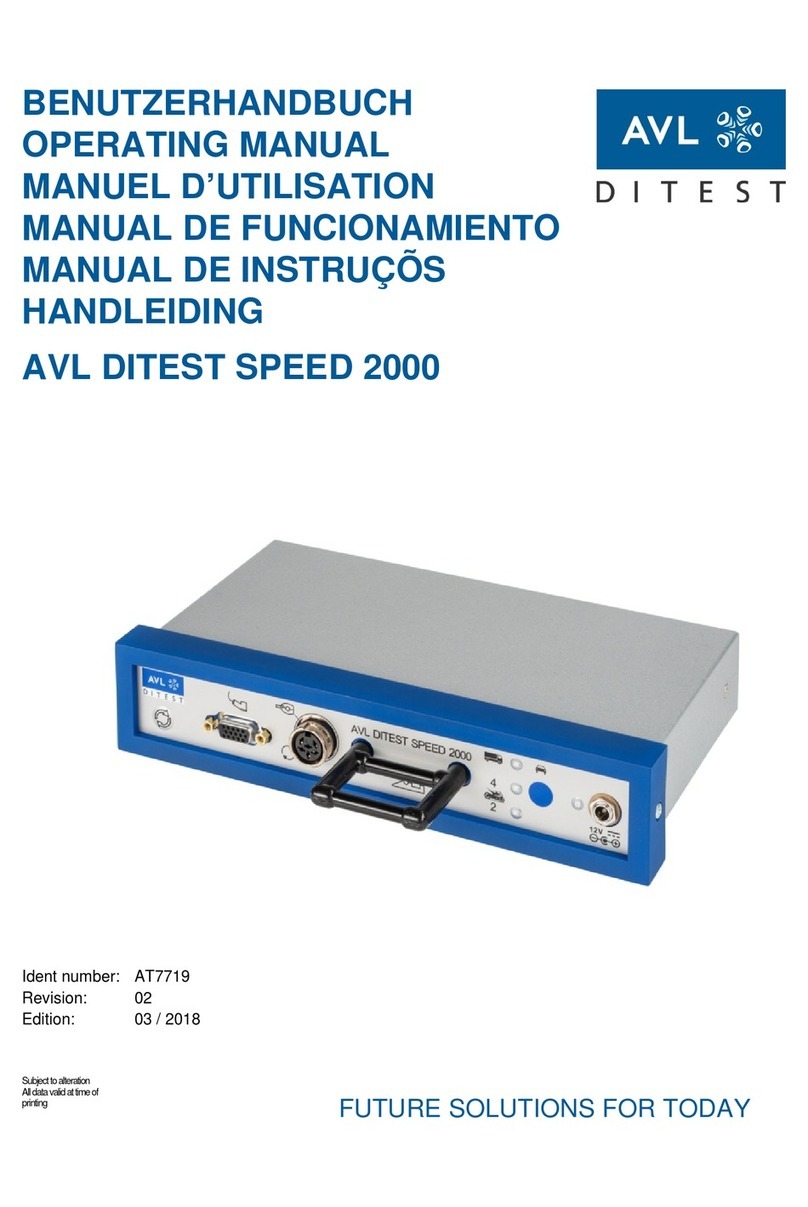
AVL DITEST COUNTER User manual

USER MANUAL
AVL DiTEST COUNTER
ID number: AT8008EN
Revision: 00
Edition: 09/2021
Software version:
Data subject to change and errors.
All data valid at the time of publication.
PASSION INNOVATES FUTURE


AVL DiTEST Counter
User manual
II
Contents
1General ............................................................................................................................1
1.1Contents of the user manual............................................................................................... 1
1.2 Intended use ....................................................................................................................... 1
1.3 Target audience.................................................................................................................. 1
1.4 Expert review ...................................................................................................................... 1
2Safety ............................................................................................................................2
2.1 Safety instructions and warning signs ................................................................................ 2
2.2 General safety instructions ................................................................................................. 3
2.3 Safety concept .................................................................................................................... 5
3Design ............................................................................................................................8
4Scope of supply ............................................................................................................11
5Commissioning.............................................................................................................12
5.1 Hardware .......................................................................................................................... 12
5.2 Software............................................................................................................................ 15
6Working with the AVL DiTEST Counter .......................................................................16
6.1 DSS controlled.................................................................................................................. 16
6.1.1 Connecting to the AVL DiTEST DSS................................................................................ 16
6.2 Stand-alone mode............................................................................................................. 17
6.2.1 Screen symbols ................................................................................................................ 17
6.2.2 Routine checks ................................................................................................................. 17
6.2.3 APK Procedure (Official Measurement)............................................................................ 19
6.2.4 Operation .......................................................................................................................... 22
7Maintenance ..................................................................................................................26
7.1 Visual inspection............................................................................................................... 27
7.2 Maintenance schedule...................................................................................................... 28
7.3 Cleaning............................................................................................................................ 29
7.4 USB cable......................................................................................................................... 29
7.5 Exhaust gas probes.......................................................................................................... 29
7.6 External visual inspection ................................................................................................. 29
7.7 Filter.................................................................................................................................. 30
7.8 Calibration......................................................................................................................... 32
8Warranty ........................................................................................................................33
8.1 New devices...................................................................................................................... 33
8.2 Case of damage................................................................................................................ 33
9Errors and error elimination.........................................................................................33
9.1 Fault, symptom, cause and remedy.................................................................................. 34
9.2 Problem reports / service addresses................................................................................ 37
10 Technical data...............................................................................................................38
10.1 Disposal ............................................................................................................................ 38
10.2 CE - Declaration of Conformity......................................................................................... 39
11 Index ..........................................................................................................................40

AVL DiTEST Counter
General
1
User manual
1 General
1.1 Contents of the User Manual
This documentation describes the AVL DiTEST Counter and how to use it. The safety
instructions in section Safety and the rest of the user manual must be followed.
This document is an essential part of the device. Keep it throughout the lifetime of the device
and pass it on to any subsequent owners or users.
1.2 Intended Use
The AVL DiTEST Counter is used to test the particulate filters of motor vehicles. To do so,
the device determines the particle count in the exhaust gas flow.
The device is intended for use indoors and occasionally outdoors
The device must be operated on the workshop floor and must not be placed on shelves or
other constructions.
The AVL DiTEST Counter is controlled by AVL DiTEST DSS (DSS: Diagnostic System
Software). For this, the device is connected to the AVL DiTEST MDS computer or the AVL
DiTEST CDS station with the USB cable.
It can also be connected to the AVL DiTEST MDS computer (or CDS computer) via
Bluetooth.
The AVL DiTEST Counter can also be used as a stand-alone device. In this case, the
device is operated via the LC display and the keys below.
No responsibility or liability is assumed for any use beyond its intended purpose or in the
case of non-compliance with the necessary requirements and safety measures.
1.3 Target Audience
The AVL DiTEST Counter is intended for testing organisations, automotive repair/service
shops or similar institutions.
It is intended exclusively for professionally trained users.
Observe the regulations applicable in your country.
1.4 Expert Review
Since the measuring results of this product depend not only on the proper functioning of
the product itself, but also on a number of other boundary conditions, it is essential that
the results provided by the product be reviewed by an expert (plausibility check) before
any further measures based on these measuring results be made.

Safety
AVL DiTEST Counter
User manual
2
2 Safety
This manual contains important warnings and safety instructions that must be observed by the
user. Non-observance of the information on these dangers can lead to death or serious injury.
2.1 Safety Instructions and Warning Signs
The following safety instructions and additional safety symbols are used in this documentation:
WARNING
WARNING indicates a dangerous situation which, if not avoided, can lead to death or
serious injury.
CAUTION
CAUTION indicates a dangerous situation which, if not avoided, can lead to minor or
moderate injury.
Additional Safety Symbols
Non-observance of the following instructions can cause life-threatening injuries and
damage to property.
Danger from high voltage
Danger from explosion
Danger from hot parts

AVL DiTEST Counter
Safety
3
User manual
Notices:
Notice
This term refers to situations or operating errors that can lead to damage or data loss.
Information
This term indicates important information or instructions. Failure to follow these
instructions will significantly prevent or hinder the successful execution of the actions
described in this documentation.
2.2 General Safety Instructions
➢When using the product, a professional must ensure that the test object or test
system cannot enter operating modes that could cause injuries or damage.
➢Test and assembly work must only be carried out by trained personnel.
➢Never use devices with defective cable guides which are clearly damaged or which
show damage due to falls. Such devices must first be checked by qualified service
personnel.
➢Read the operations manual completely and carefully.
➢If the device falls or is damaged, have it checked by a qualified service technician
before resuming operation.
➢Make sure that cables are not stretched or kinked or come into contact with sharp
edges.
➢Do not let the device come into contact with hot or moving parts.
➢Always disconnect the device from the connections when not in use.
➢Pull the plug, not the cable, to remove the plug from the USB port.
➢Let the device cool down completely before putting it away.
➢To reduce the risk of fire, do not operate the device near open vessels with
flammable liquids (petrol).
➢Ensure adequate ventilation when working on combustion engines.
➢Keep hair, loose clothing, fingers and all body parts away from moving parts.
➢Operate the device only as described in this manual.

Safety
AVL DiTEST Counter
User manual
4
➢Only use accessories recommended by the manufacturer.
➢Secure the vehicle sufficiently against rolling away.
➢The plug of the heating hose may only be used to plug in the heating hose.

AVL DiTEST Counter
Safety
5
User manual
2.3 Safety Concept
WARNING
Danger due to harmful or irritant substances
Measurements taken while the engine is running can release substances that are hazardous to
health.
When measuring with the engine running in closed rooms (workshops, test halls, etc.), discharge
the vehicle exhaust gases and ensure sufficient ventilation in the rooms.
v
WARNING
Risk of burns from hot parts
Perform measurements at normal engine operating temperature or according to the test
specification. Do not touch hot parts such as the engine, engine attachments or the entire
exhaust system. Use cooling fans if necessary.
WARNING
Risk of injury due to rotating parts
If possible, carry out all work in the engine compartment with the engine stopped and the ignition
switched off. Do not touch rotating parts such as the alternator, the cooling fan and their drives
(e.g. V belts).
WARNING
Explosion or fire hazard due to gases and/or vapours
The device must not be operated near open fuel tanks, as otherwise there is a risk of explosion or
fire due to gases and/or vapours.
v
WARNING
Risk of burns from hot parts
The heating hose connection heats up to over 55 °C. Wear safety gloves when handling the
hose.
v
WARNING
Danger to life due to electrical voltage
Only use sockets with ground connection for the supply of the device

Safety
AVL DiTEST Counter
User manual
6
v
WARNING
Danger to life due to electrical voltage
Maintenance is must only be performed with the device switched off and disconnect power plug.

AVL DiTEST Counter
Safety
7
User manual
Observe the applicable manufacturer's specifications when maintaining the adjustment speed of
diesel engines.
Always switch off the ignition before connecting or disconnecting the OBD plug / the different AVL
DiTEST vehicle adapters.
Never leave the probe lying on the ground. Make sure that neither liquids (e.g. water) nor other
impurities get into the exhaust gas measuring device via the probe.
NOTICE
NOTICE
NOTICE

Design
AVL DiTEST Counter
User manual
8
3 Design
AVL DiTEST Counter, Front View
The following figure shows the front of the device:
(1) LC display
(2) Control buttons
(3) HEATING (hose heating connection)
(4) GAS IN, exhaust gas inlet/probe connection
(5) TEST IN
(6) GAS OUT
Fig. 1: Front view of the AVL DiTEST Counter (exemplary)
1
2
4
3
6
5

AVL DiTEST Counter
Design
9
User manual
AVL DiTEST Counter, Rear View
The following figure shows the rear of the device:
(1) “Power” switch
(2) Mains plug connection
(3) “USB Type B” port
(4) “USB Type A” port
(5) Handle
Fig. 2: Rear view of the AVL DiTEST Counter (exemplary)
1
2
3
4
3
9
0
2
2
1
0
8
4
5

Design
AVL DiTEST Counter
User manual
10
Fig. 3: Power cable (exemplary)
Fig. 4: Sampling line of the AVL DiTEST Counter (exemplary)
Power Cable
Exhaust Gas Probe
(1) Probe tip
(2) Handle for exhaust probe mount
(3) Heating hose with connections
3
2
1

AVL DiTEST COUNTER
Scope of Supply
11
User manual
4 Scope of Supply
The following table gives an overview of the scope of supply:
Standard part
Accessories
AVL DiTEST Counter
●
Power cable, country specific
(Example: C13 Euro power cable)
●
●
Exhaust gas probe
●
●
Heating hose
●
●
USB cable
●

Commissioning
AVL DiTEST Counter
User manual
12
5 Commissioning
5.1 Hardware
Site of Installation
The device should be installed on the workshop floor. If the device is used in another position (e.g.,
placed on shelves or other constructions), the device must be secured against dropping.
Make sure that the installation site meets the following requirements:
•The device must not be exposed to direct sunlight.
•The device must not be exposed to excessive heat.
•The power supply connection must be freely accessible.
•Do not place the device directly next to the exhaust.
WARNING
Explosion or fire hazard due to gases and/or vapours
The device must not be operated near open fuel tanks, as otherwise there is a risk of explosion or
fire due to gases and/or vapours.

AVL DiTEST Counter
Commissioning
13
User manual
USB Cable and Power Supply
1. Connect the USB cable to the AVL DiTEST Counter, connector "USB" (3).
Tighten the screw cap on the USB plug (when using computer, skip in stand-alone
mode).
2. Connect the USB cable to the computer (when using a computer, skip in stand-alone
mode).
3. Connect the mains plug to the socket (2).
4. Insert the mains plug into a plug socket.
5. Switch on the AVL DiTEST Counter with the power switch (1).
When the device starts, the AVL DiTEST Counter displays the bootloader and firmware
version and performs a self-test. The device then warms up and switches to standby
mode.
Fig. 5: Connecting the AVL DiTEST Counter on the back side
1
2
3

Commissioning
AVL DiTEST Counter
User manual
14
v
Exhaust Gas Probe, Hose
v
WARNING
Risk of burns from hot parts
The heating hose connection heats up to over 55 °C. Wear safety gloves when handling the
hose.
1. Connect the heating hose to the "GAS IN" connection (1).
2. Connect the heating cable to the "HEATING" connection (3).
3. Connect the exhaust gas probe with the connecting hose to the "GAS IN"
connection (1).
4. Make sure that the exhaust gas can flow out unhindered at "GAS OUT" (2).
Fig. 6: Connecting the AVL DiTEST Counter on the front side
1
2
3

AVL DiTEST Counter
Commissioning
15
User manual
Information
We recommend connecting an exhaust air bypass to "GAS OUT". The connection is a
standardised compressed air quick coupling with a nominal diameter of 7.2.
5.2 Software
AVL DiTEST DSS is installed and updated via AVL DiTEST DSS. Please refer to the
document AT7260 DSS Installation and update.

Working with the AVL DiTEST Counter
AVL DiTEST Counter
User manual
16
6 Working with the AVL DiTEST Counter
6.1 DSS Controlled
6.1.1 Connecting to the AVL DiTEST DSS
The primary operating mode is the connection of the AVL DiTEST Counter to the AVL
DiTEST DSS. Please refer to the AT7683 AVL DiTEST DSS user manual.
Table of contents
Other AVL DITEST Measuring Instrument manuals