AV-70 Solar Aviation Light
Installation & Service Manual
Latest products and information available at www.avlite.com 5
2.0 Technology
Avlite Systems is a world-class solar lighting systems manufacturer with a proven
reputation for rapid, innovative, and agile technology solutions designed specifically
for defence, government, civil and humanitarian aid operations in the most remote,
toughest environments.
Electronics
Avlite employs leading in-house electronic engineers in the design and development of
software and related circuitry. All individual electronic components are sourced directly by
Avlite procurement staff ensuring that only the highest quality components are used in our
products.
LED Technology
All Avlite lights use the latest advancements in LED (Light Emitting Diode) technology as a
light source. The major advantage of LED’s over traditional light sources is well established
in that they typically have an operational life in excess of 100,000 hours, resulting in
substantial savings to maintenance and servicing costs.
Precision Construction
Commitment to investing in the design and construction of injection-moulded parts
including optic lenses, light bases and a range of other components ensures that all Avlite
products are of a consistent and superior quality.
Optical Performance
Avlite manufactures a range of aviation LED lenses moulded from multi-cavity dies. The
company has superior in-house lens manufacturing capabilities to support outstanding
optical performance.
Award-winning, Patented Technology
Several United States and Australian patent registrations are held on Avlite’s range of
innovative designs, with other regional patents pending in Canada, United Kingdom and
Europe.
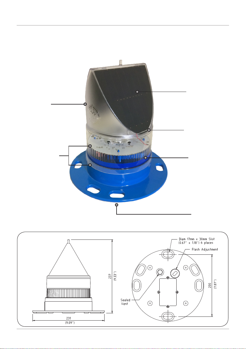
Operating Principle
The solar module of the light converts sunlight to an electrical current that is used to
charge the battery. The battery provides power to operate the light at night. For optimum
solar charge performance it is recommended that the unit is orientated with the solar
panels facing East-West.
The flasher unit has very low current requirements. A microprocessor drives an array of
ultra bright LED’s through a DC/DC converter, which enables the LED’s to operate within
the manufacturer’s specifications. The battery is protected from over-charging within the
circuit to ensure maximum battery life.
On darkness, the microprocessor will initiate a program check and after approximately 1
minute will turn on.