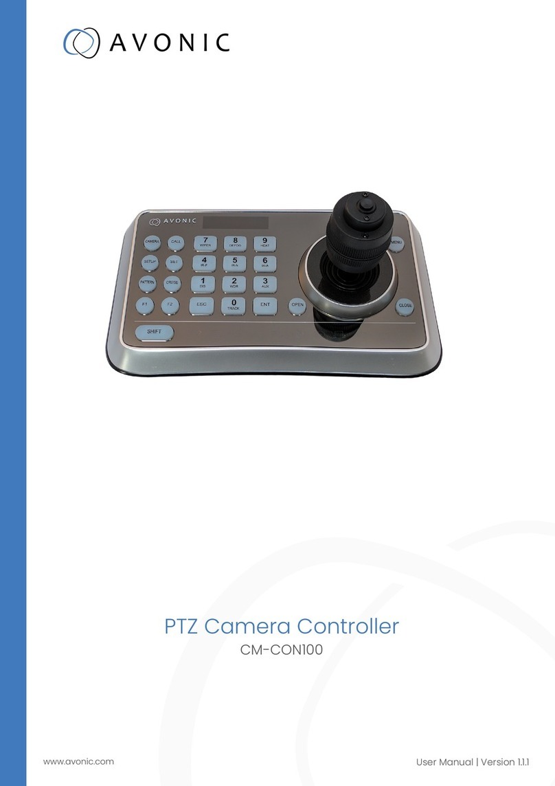
Avonic CM-CON100 User manual

USER MANUAL
PTZ Camera Controller
CM-CON100
www.avonic.com • © August 2023 • Version 1.3.4

DISCLAIMER, CONTACT AND MARKINGS
Disclaimer
All text, graphics, photographs, trademarks, logos, artwork and computer code (collectively, “Content”), including
but not limited to the design, structure, selection, coordination, expression, “look and feel” and arrangement of
such Content, contained in this Manual is owned, controlled or licensed by or to Avonic, and is protected by trade
dress, copyright, patent and trademark laws, and various other intellectual property rights and unfair competition
laws.
Except as expressly provided in these Terms of Use, no Content of this Manual may be copied, reproduced,
republished, uploaded, posted, publicly displayed, encoded, translated, transmitted or distributed in any way
(including “mirroring”) to any other computer, server, Website or other medium for publication or distribution or for
any commercial enterprise, without the prior written consent of Avonic.
Copyright © 2023 AVONIC All Rights Reserved.
The information contained in this Manual is subject to change without notice.
Contact Info
For any questions or suggestions, contact your reseller or local distributor of Avonic.
Visit the Avonic website www.avonic.com to find your local Avonic distributor or to download the most recent
version of the documentation.
Join Avonic on Social Media
www.Facebook.com/avonicPTZ www.instagram.com/avonicPTZ
www.LinkedIn.com/company/avonic www.youtube.com/channels/avonic
www.twitter.com/avonic
Markings
The Product has a Markings. The labels are placed at the bottom of the Product and on the packaging. See the
respective figures below:
Figure 1: Markings (Product) Figure 2: Markings (Packaging)
ii

CE DECLARATION OF CONFORMITY
Table 1: CE Declaration of Conformity
CE DECLARATION OF CONFORMITY
1. Models No: CM-CON100
2. Brand Name: Avonic
3. Product Name: PTZ Camera Controller
4. Manufacturer: Avonic
Exportweg 11a
2645ED Delfgauw
The Netherlands
3. This declaration of conformity is issued under the sole responsibility of the manufacturer
4. The object of the declaration described in point 1 is in conformity with the EMC2014/30/EU
5. Standards EN 55022: 2010
EN 55024: 2010+A1: 2015
EN 61000-3-2: 2014
EN 61000-3-3: 2013
6. Signed for and on behalf of Avonic:
Delfgauw, 25th of April, 2019
Martijn van Bodegom,
Product Manager
American Certification
Look for American certification on the product/package for the FCC logo.
iii

IMPORTANT INFORMATION
Liability
Avonic will NOT be held responsible for any damage or injury caused by unqualified persons carrying out these
tasks, or by not following the instructions in this Manual.
Intended Use and Non-Intended Use
Installation
The following applies to the installation of the CON100:
• The installation activities described in this Manual should ONLY be executed by experienced technicians.
• The installation activities should NOT be executed by minors, mentally disabled persons or other persons
not qualified to perform these tasks.
Operation
The following applies to the operation of the CON100:
• The operational activities described in this Manual should ONLY be executed by people with enough
technical knowledge to perform the activities in a safe manner.
• This Product is specifically developed for video conferencing / streaming via internet by companies,
institutes and universities. It is NOT meant for private use in the residential area.
• This Product should ONLY be used indoors.
• This Product is NOT a medical device and should NOT be used as a substitute for professional medical
judgment. It is NOT designed or intended for use in the diagnosis of disease or other conditions, or in the
cure, mitigation, treatment, or prevention of any condition or disease. Please consult your healthcare
provider prior to making any decisions related to your health.
Important Precautions
The Product is NOT intended for use where failure of the device could lead to death, personal
injury, or severe environmental damage.
Failure to follow the SAFETY NOTES as described in this chapter could result in fire, electric
shock, injury, or damage to the Product or other property.
Power the Product ONLY with the included cable and power adapter. Other adapters
may not meet applicable safety standards, and could pose a risk of death or injury when
connected.
To prevent the risk of injury or damage to the Product or other property caused by a
potentially explosive atmosphere.
Be sure that you have COMPLETELY READ and UNDERSTOOD ALL information in this Manual
before unpacking, installing and using this Product. Keep the Manual in a safe place for future
reference or download it from www.avonic.com.
Symbols Used in This Manual
Symbol Meaning Description
Danger Not following the instructions associated with this symbol may lead to
life-threatening situations and / or serious damage to the Product.
Warning Not following the instructions associated with this symbol may lead to
personal injury and / or serious damage to the Product.
iv

Symbol Meaning Description
Caution Caution should be exercised with the associated information.
Information The information associated with symbol refers to a general remark or a
reference to other documentation.
Instruction This symbol refers to one or more user instructions.
Recycling Specific parts of the Product can be re-used.
Acronyms
The following acronyms are used in this Manual:
JEITA
connector
Japan Electronics and
Information Technology
Industries Association
A "JEITA Connector" refers to a connector that adheres to the specifications set forth by
JEITA for a particular type of electronic or electrical connection. JEITA connectors can cover
a wide range of applications, including audio/video connectors, power connectors, data
connectors, and more. These connectors are designed to ensure compatibility, safety, and
reliability in electronic devices and systems.
OSD On-Screen Display Display menu that appears on your monitor screen when the camera is connected to IP,
SDI or HDMI.
PTZ Pan / Tilt / Zoom Directions to which the lens moves: Pan (horizontal), Tilt (vertical) and Zoom (magnify objects
on large distance).
PSU Power Supply Power adapter of the controller.
RS232 Recommend Standard 232 Communication protocol used for serial communication between devices.
RS485 Recommend Standard 485 Communication protocol used for serial communication between devices over long
distances. It is an extension of the RS-232 protocol and is designed to overcome the
limitations of RS-232, such as limited range and susceptibility to noise.
SKU Stock Keeping Unit Stock keeping unit used by Avonic. Every camera has an unique SKU with AV-CM (Avonic
Camera).
v

Contents
DISCLAIMER, CONTACT AND MARKINGS............................................................................................ ii
CE DECLARATION OF CONFORMITY...................................................................................................iii
IMPORTANT INFORMATION.................................................................................................................. iv
Liability................................................................................................................................................... iv
Intended Use and Non-Intended Use................................................................................................iv
Installation............................................................................................................................................. iv
Operation..............................................................................................................................................iv
Important Precautions......................................................................................................................... iv
Symbols Used in This Manual.............................................................................................................. iv
Acronyms............................................................................................................................................... v
INTRODUCTION...................................................................................................................................... 8
Purpose of This Manual........................................................................................................................ 8
Target Audience...................................................................................................................................8
Document Structure............................................................................................................................. 8
SAFETY INSTRUCTIONS........................................................................................................................... 9
Important Precautions..........................................................................................................................9
Intended Use.........................................................................................................................................9
Handling.................................................................................................................................................9
Installation.............................................................................................................................................. 9
Ventilation..............................................................................................................................................9
Repair................................................................................................................................................... 10
Power and Adapter........................................................................................................................... 10
Atmospheric Conditions.....................................................................................................................10
PRODUCT OVERVIEW..........................................................................................................................11
Description........................................................................................................................................... 11
Features............................................................................................................................................... 11
UNPACKING.........................................................................................................................................12
Package Contents............................................................................................................................. 12
Unpacking the Controller...................................................................................................................13
Return Procedure................................................................................................................................13
INSTALLATION.......................................................................................................................................14
Connecting a Controller to a Camera............................................................................................ 14
RS-232 Interface.................................................................................................................................. 14
RS-485 Interface.................................................................................................................................. 15
RS-232 (VISCA) Network Connection................................................................................................15
RS-485 Network Connection..............................................................................................................15
OPERATION.......................................................................................................................................... 16
Connections........................................................................................................................................ 16
Start...................................................................................................................................................... 17
Non-Setup Menu.................................................................................................................................17
Buttons to control the camera (non-setup menu).......................................................................... 17
PTZ Controls......................................................................................................................................... 18
Zoom and Focus.................................................................................................................................18
SET/ CALL Preset Position....................................................................................................................18
Delete Preset Position.........................................................................................................................19
How to switch to another camera................................................................................................... 19
Setup Menu.........................................................................................................................................19
Buttons to control the camera (setup menu)..................................................................................20
1. Camera Setting.............................................................................................................................. 20
2. Time Setting.....................................................................................................................................21
3. Volume Setting............................................................................................................................... 21
vi
4. Backlight Setting............................................................................................................................. 22
5. Sleep Setting................................................................................................................................... 22
6. PIN setting (and what to do if the PIN is lost).............................................................................. 22
7. Joystick Calibration........................................................................................................................ 23
8. Key Custom.....................................................................................................................................23
9. Speed Setting................................................................................................................................. 24
10. Default Setup................................................................................................................................ 25
11. Information.................................................................................................................................... 25
OSD Menu (Camera).........................................................................................................................26
Buttons to control the OSD menu of the camera...........................................................................26
OSD menu instructions....................................................................................................................... 26
MAINTENANCE.....................................................................................................................................27
Maintenance.......................................................................................................................................27
Usage Precautions..............................................................................................................................27
TRANSPORT AND STORAGE................................................................................................................28
DISPOSAL AND RECYCLING............................................................................................................... 29
TROUBLESHOOTING............................................................................................................................. 30
General................................................................................................................................................ 30
Power Issues.........................................................................................................................................30
Serial functionality issues.................................................................................................................... 30
APPENDIX A - DATASHEET SPECIFICATIONS...................................................................................... 31
SPECIFICATIONS...................................................................................................................................31
Index..................................................................................................................................... 32
vii

INTRODUCTION
Purpose of This Manual
The purpose of this manual is to provide safety instructions and guidelines for the proper unpacking, installation,
operation, maintenance, and disposal of the Avonic CM-CON100.
In this Manual, the Avonic CM-CON100 is referred to as the 'Product'.
Target Audience
This Manual is developed for installation technicians who install the Product at client sites, and for IT professionals
who are responsible for operating the Product.
Document Structure
The Manual is subdivided into the following Chapters:
1. Introduction
2. Safety
3. Product Overview
4. Unpacking
5. Mounting and Installation
6. Operation
7. Maintenance
8. Transport and Storage
9. Disposal and Recycling
10. Troubleshooting
The following appendices are added to this manual:
•Appendix A - Datasheet Specifications
8

SAFETY INSTRUCTIONS
This chapter contains important safety information regarding the unpacking, installation and use of the camera.
Important Precautions
The Product is NOT intended for use where failure of the device could lead to death, personal
injury, or severe environmental damage.
Failure to follow the SAFETY NOTES as described in this chapter could result in fire, electric
shock, injury, or damage to the Product or other property.
Power the Product ONLY with the included cable and power adapter. Other adapters
may not meet applicable safety standards, and could pose a risk of death or injury when
connected.
To prevent the risk of injury or damage to the Product or other property caused by a
potentially explosive atmosphere.
Be sure that you have COMPLETELY READ and UNDERSTOOD ALL information in this Manual
before unpacking, installing and using this Product. Keep the Manual in a safe place for future
reference or download it from www.avonic.com.
Intended Use
This Product is intended to control the Avonic PTZ cameras. See also section Intended Use and Non-
Intended Use on page iv for details.
Handling
To prevent the risk of injury, take the following precautions when handling this Product:
• Handle the Product with care. It is made of metal and plastic and has sensitive electronic components
inside.
• The Product can be damaged if dropped, burned, punctured or crushed, or if it comes into contact with
liquid.
• If you suspect any damage to the Product, discontinue its use, as it may cause overheating or injury.
Installation
To prevent the Product from falling down which may cause injuries:
• Set up this Product on a hard, stable surface.
• Ensure the construction is capable of supporting four times the weight of the Product. (See 'General
Specifications > Weight product’ in the Product Datasheet for the exact weight.)
• Use a safety loop or drop protection that prevents the Product from falling if the construction fails.
• During installation, NEVER install a Product above a person.
• Check the installation at least once a year. An improper construction could cause the unit to fall off,
resulting in personal injury.
Ventilation
To prevent the risk of life-threatening injury or damage to the Product or other property, caused by electric
shock or fire hazard due to overheating:
• Maintain adequate ventilation by NOT installing or placing the Product unit in a bookcase, built-in
cabinet or any other confined space.
• Ensure that curtains or any other material does NOT obstruct the ventilation.
9

Repair
Take the following precautions if the Product should be repaired:
• Don’t open this Product and don’t attempt to repair it yourself. Disassembling the Product may damage
it or may cause injury to you.
• If this Product is damaged, malfunctioning, or if it comes into contact with liquid, contact Avonic or an
Avonic Authorized Service Provider.
• Repairs by service providers other than Avonic or an Avonic Authorized Service Provider may not involve
the use of Avonic genuine parts and may affect the safety and functionality of the device. You can find
more information about repairs and service at www.avonic.com.
Power and Adapter
To prevent the risk of life-threatening injury or damage to the Product or other property, caused by electric
shock or fire hazard:
• Power this Product ONLY with the included cable and power adapter. Other adapters may not meet the
applicable safety standards. They could pose a risk of death or injury when connected.
• Do NOT use damaged cables.
• Do NOT power the Product in a moist / wet environment.
• Before you power the Product, ensure the cable is fully inserted into the power adapter.
• Plug the power adapter directly into a power outlet.
• Do NOT use the power adapter at a moist / wet location.
• Do NOT connect or disconnect the power adapter with wet hands.
• Keep the Product, cable, and power adapter in a dry and well-ventilated area when in use.
• Stop using the power adapter and any cables if any of the following conditions exist:
• The power adapter plug or prongs are damaged.
• The cable becomes frayed or otherwise damaged.
• The power adapter is exposed to excessive moisture, or liquid is spilled into it.
• The power adapter has been dropped, and its enclosure is damaged.
Atmospheric Conditions
To prevent the risk of injury or damage to the Product or other property caused by a potentially explosive
atmosphere:
• Do NOT use this Product in an area with a potentially explosive atmosphere, such as areas where the air
contains high levels of flammable chemicals, vapors, or particles (such as grain, dust, or metal powders),
may be hazardous.
• Exposing this Product to environments having high concentrations of industrial chemicals, including near
evaporating liquified gasses such as helium, may damage or impair this Product functionality.
• Obey all signs and instructions.
10

PRODUCT OVERVIEW
Description
The Avonic CM-CON100 is a compact PTZ camera controller. With this controller it is possible to control
up to 255 camera’s and using up to 255 presets. The controller supports the Visca, Pelco-D and Pelco-P
protocol and can be connected with RS232/485. The Avonic CM-CON100 is therefore compatible with
the Avonic camera’s as well with other brands that supports these protocols. Switch easily between auto
and manual focus, save and load presets, and connect multiple controllers to multiple camera’s.
Features
The Avonic CON100 has the following features:
Number of Presets
With this compact controller, it is possible to control up to 255 cameras and use up to 255 presets.
Connection
Easy to connect with RS232 , RS485
Control
Every setting of the camera can be controlled by accessing the OSD of the camera through the controller. Directly control the camera’s
Pan, Tilt, Zoom and Focus.
11

UNPACKING
This chapter provides the contents of a complete Product package, and instructions for safe unpacking and (if
necessary) Product return.
It is subdivided into the following sections:
1. Package Contents
2. Unpacking the Controller
3. Return Procedure
Package Contents
The following tables contains an overview of the package contents of the Product.
No. Quantity Description Avonic SKU
1 1 pc PTZ Camera Controller CM-CON100
2 1 pc * Power Supply CM-CON100-PSU
Each item is visualized below and referenced by the associated number in the table above:
Figure 3: Package Contents
Power Adapter Usage
Note
: * Use only the Power Adapter "Switching Power Supply" of GME Technology (Shenzhen) Co., ltd in
combination with the CON100. Using another Power Adapter may lead to injury and/or damage to the
product. See the picture of the Power Adapter label below:
Figure 4: Power Adapter label
12

Unpacking the Controller
Execute the following steps to unpack the CON100 and associated components:
1. Open the box.
2. Verify that the contents of the box exactly matches the items as described in Package Contents on page 12.
If this is NOT the case, contact Avonic and stop here.
The CON100 should be in its protective foam as follows:
Figure 5: Controller in Foam
3. Verify that the plastic bag is sealed. If this is NOT the case, contact Avonic and stop here.
4. Break the seal of the sealed bag.
5. Take the CON100 out of the bag.
6. Install the CON100 following the steps as described in the chapter INSTALLATION on page 14
Return Procedure
If, for any reason, you have to return the camera to Avonic, execute the following steps:
1. Place the CON100 back in its protective foam.
2. Place the CON100 with all of its components in the box.
3. Verify that the contents of the box exactly matches the items as described in Package Contents.
4. Contact Avonic for the Return Procedure.
13

INSTALLATION
This chapter outlines the steps you have to perform to mount and install the Product in a correct and safe manner.
The installation of the controller can be done in two ways:
1. Connecting a controller to a Camera
2. via IP (Network) Connection
Take the following precautions to prevent the Product from falling down which may cause injuries:
• Set up this Product on a hard, stable surface.
• Ensure the mounting construction is capable of supporting four times the weight of the Product. (See
'General Specifications > Weight product’ in the Product Datasheet for the exact weight.)
• Use a safety loop or drop protection that prevents the Product from falling if the mounting construction
fails.
• During installation, NEVER install a Product above a person.
• Check the installation at least once a year. An improper installation could cause the unit to fall off,
resulting in personal injury.
Connecting a Controller to a Camera
A controller gives you direct control over the most important camera settings (e.g., Pan, Tilt, Zoom, Focus, White
Balance). You can access all other settings through the OSD Menu of the camera using the controller. The CON100
can be connected via a serial connection to (RS-232, RS-485) to one or two cameras. See below:
The controller has 3 wires:
• Power with female JEITA connector
• RS232 with 3 pin Terminal Strip
• RS485 with 2 pin Terminal Strip
1. Connect the provided PSU cable to the female Jeita connector and the power net.
2. Connect the RS232 and/or RS485 cable to one and/or a second camera. Use for this a Phoenix connector and
follow the instructions in RS-232 Interface on page 14 and/or RS-485 Interface on page 15. See also
the picture below:
RS-232 Interface
Connect the controller to the back of the camera via RS-232 cables as shown in the figures below:
14

Figure 6: RS-232 Interface (Mini
DIN-8)
Figure 7: RS-232 Cable and Interface
Connection (Mini DIN-8 and Windows DB-9)
RS-485 Interface
Connect the controller to the + and - at the back of the camera via the RS-485 cables, as shown in the
figure below. The color of the connecting cables (red and black) may vary.
Figure 8: RS-485 Interface
RS-232 (VISCA) Network Connection
Execute the following steps to connect the controller to the back of the camera(s) via RS-232:
1. Make the connection using daisy chaining network architecture.
2. Keep in mind that the maximum cable length for RS-232 is 10-15m.
Figure 9: RS-232 Network Connection Diagram
RS-485 Network Connection
Execute the following steps to connect multiple cameras to RS-485:
1. Attach the cameras to a 2-wire twisted pair bus (maximum length 1200m) that is terminated at both
ends with a 120Ω-impedance resistor.
2. Ensure that the maximum distance from the bus to the camera or controller is 5m. If you use only ONE
camera, the impedance resistor is not needed.
Figure 10: RS-485 Network Connection Diagram
15

OPERATION
This chapter will explain the operation instructions for using the CON100.
Connections
Prior to the initial use of the CON100, an explanation of the buttons and their respective functions will be provided.
See below:
No. Name Functionality
1. OLED Screen Displays status of current operation
From top to bottom:
2. CAMERA Switch camera’s
CALL Call a preset
SETUP Change keyboard settings
SET Set or delete a preset
PATTERN No Functionality *
CRUISE No Functionality *
F1, F2 Switch autofocus/ manual focus
SHIFT Extension key for special functions
3. ESC EXIT / delete a wrong insert in Setup Menu
4. Number Buttons Input numbers for the use of SET/CALL functionality, Camera ID and address.
5. ENT(er) Confirm menu settings
6. OPEN Actives IRIS open of the camera/ Confirm button in OSD menu
7. CLOSE Close IRIS of the camera
8. Status Display area No functionality. Only lights on the display will go ON and OFF
9. MENU Enter camera (OSD) menu
10. Joystick Pan, Tilt, Zoom and Focus
Joystick Button Switch Zoom/ Focus
* While these buttons do not have any designated functionality, they may occasionally be used for creating
presets. However, it cannot be guaranteed that this method will work consistently.
16

Start
Once you have connected the cables to your camera as described in the previous chapter, the CON100 will start
automatically. Upon the CON100 is started for the first time, the User PIN will be displayed on the screen.
1. Press to fill in the pin. The initial pin is “111111”.
Pin Error: When “USER PIN: ERROR” shows on screen, it indicates wrong pin was set. Type the correct
pin to enter the next step.
Pin Correct: Screen shows “1” camera icon and default camera number. If there is no operation,
after 5 seconds the screen will display the current time. If still no operations, the controller will enter
sleep mode (30sec, 1min, 5min, 10min, 30 min or 60 min.)
After the PIN is correctly entered, you can operate the CON100. The CON100 has three different “Menu’s”:
•Non-Setup menu: to control a camera while filming.
•Setup menu: to change the settings of the CON100.
•OSD menu: to control and change the camera settings itself.
Non-Setup Menu
Buttons to control the camera (non-setup menu)
The following buttons and button combinations can be used to control the camera in Non Setup Menu:
Functionality Buttons
Call a preset
Set a preset
Delete a preset
Switch camera’s
Pan, Tilt
Zoom Tele, Focus Far
17

Functionality Buttons
Zoom wide, Focus Near
Switch between Zoom and Focus
Autofocus
Manual Focus
Iris Open
Iris Close
PTZ Controls
Move the Joystick up, down, left and right (1) to control the camera. Turn the joystick clockwise to zoom in (2) and
anti-clockwise to zoom out (3). The button on the joystick is for switching between zoom and focus. See pictures
below:
1. 2. 3.
Zoom and Focus
There are two ways to switch to Focus mode: either by pressing the Joystick button (as shown in the picture
above), or by pressing the F2 button.
1. Press F2 to switch to Focus mode and twist the joystick left and right to focus.
2. Press F1 to switch back to Zoom mode. You need to twist the joystick again to autofocus the camera
and zoom out.
SET/ CALL Preset Position
With the CON100 it is possible to set the camera in a desired position as a preset. You can call that preset when
you need it.
Follow instructions below to Set a Preset:
1. Move the joystick to set the camera in the desired position.
2. Press short number 1 button (or another number button between 0 - 255).
3. Press short the SET button to set the preset.
18

Follow the instructions below to Call a Preset:
1. Press number 1 button (or another number button between 0 - 255).
2. Press the to call the preset. The camera moves automatically in the position of that preset number.
It is important to be aware that the Preset/CALL functionality should not be confused with the process of
setting up the camera's protocol address and ID number. It is recommended to always pay attention to the
current feature and menu being used to avoid any confusion.
Delete Preset Position
To delete a preset do the following:
1. Press the number button of the preset you want to delete.
2. Wait until the camera moves to the position of that preset number.
3. Press again the number button of the preset you want to delete.
4. Press long the SET button.
5. [CLR PRESET:] shows shortly on the screen of the controller.
6. The Preset is now deleted and empty.
How to switch to another camera
See Setup Menu how to set an ID for your camera, if you have multiple camera’s to control with the
CON100.
Follow instructions below:
1. Press in the NON-Setup Menu camera number
2. Press the Camera button
Setup Menu
1. Press Setup to enter the Setup menu. Fill in the “ADMIN PIN”. The initial ADMIN PIN is “111111”.
2. The camera setting screen shows up. Use the joystick up and down to scroll through the menu.
3. Move the stick to the right to enter the menu features and move the joystick to the left to leave the
menu features.
4. It is also possible to use the Escape button to leave a menu feature, or delete a wrong insert.
19

Buttons to control the camera (setup menu)
The following buttons and button combinations can be used to control the camera in Setup Menu:
Functionality Button
Enter Setup Menu
Enter Sub Menu
Leave (Setup) Menu
Leave/ Delete wrong insert
Scroll through Menu or settings
Switch between settings
Confirm setting
Special functions / Enter extra
setting
1. Camera Setting
20
Other manuals for CM-CON100
5
Table of contents
Other Avonic Controllers manuals

Avonic
Avonic AV-CON300 User manual

Avonic
Avonic CM-CON100 User manual

Avonic
Avonic CD500 User manual

Avonic
Avonic AV-CON300-IP User manual

Avonic
Avonic CM-CON100 User manual

Avonic
Avonic CM-CON100 User manual

Avonic
Avonic CD500 User manual

Avonic
Avonic AV-CON300-IP User manual

Avonic
Avonic AV-CON300 User manual

Avonic
Avonic CM-CON100 User manual
Popular Controllers manuals by other brands

PRECISION DIGITAL
PRECISION DIGITAL Helios PD2-6310 instruction manual

AUMA
AUMA SQVEx 05.2 manual

Mitsubishi Electric
Mitsubishi Electric LGF-100GX-E Handbook

Belimo
Belimo SY4 Series QUICK MOUNT VISUAL INSTRUCTION MANUAL

omal automation
omal automation AGO DA2880 instruction manual

Toshiba
Toshiba TOSVERT VF-S15 series instruction manual