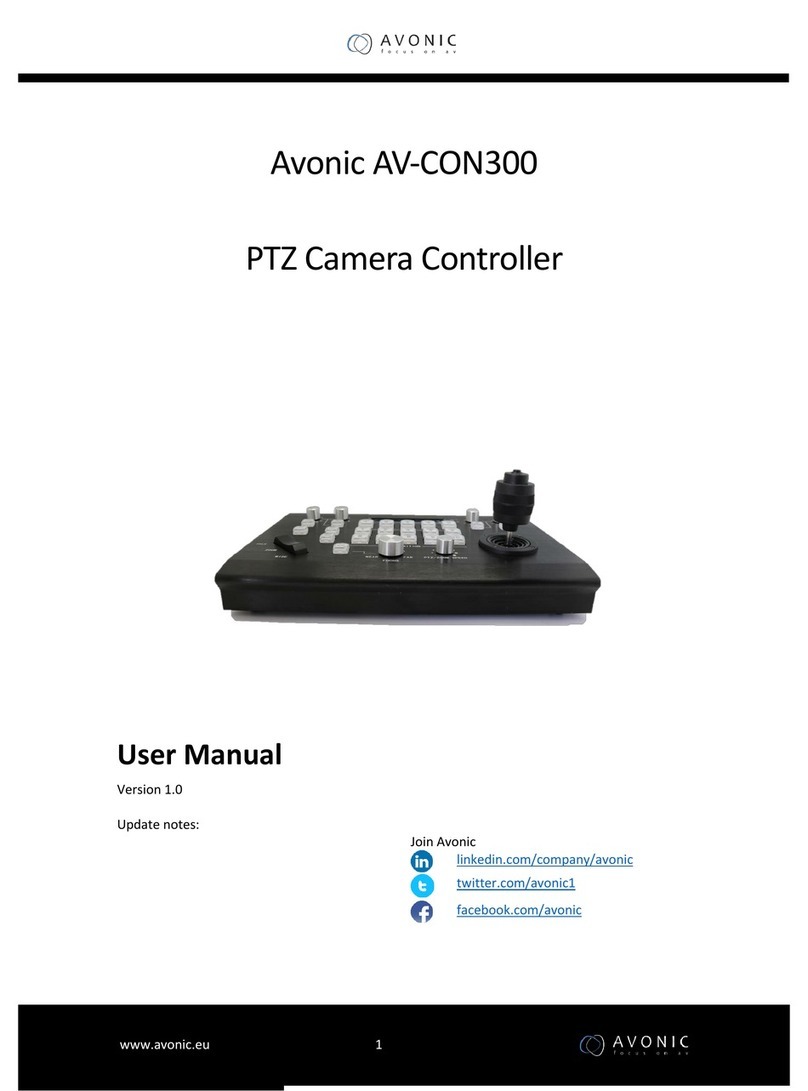
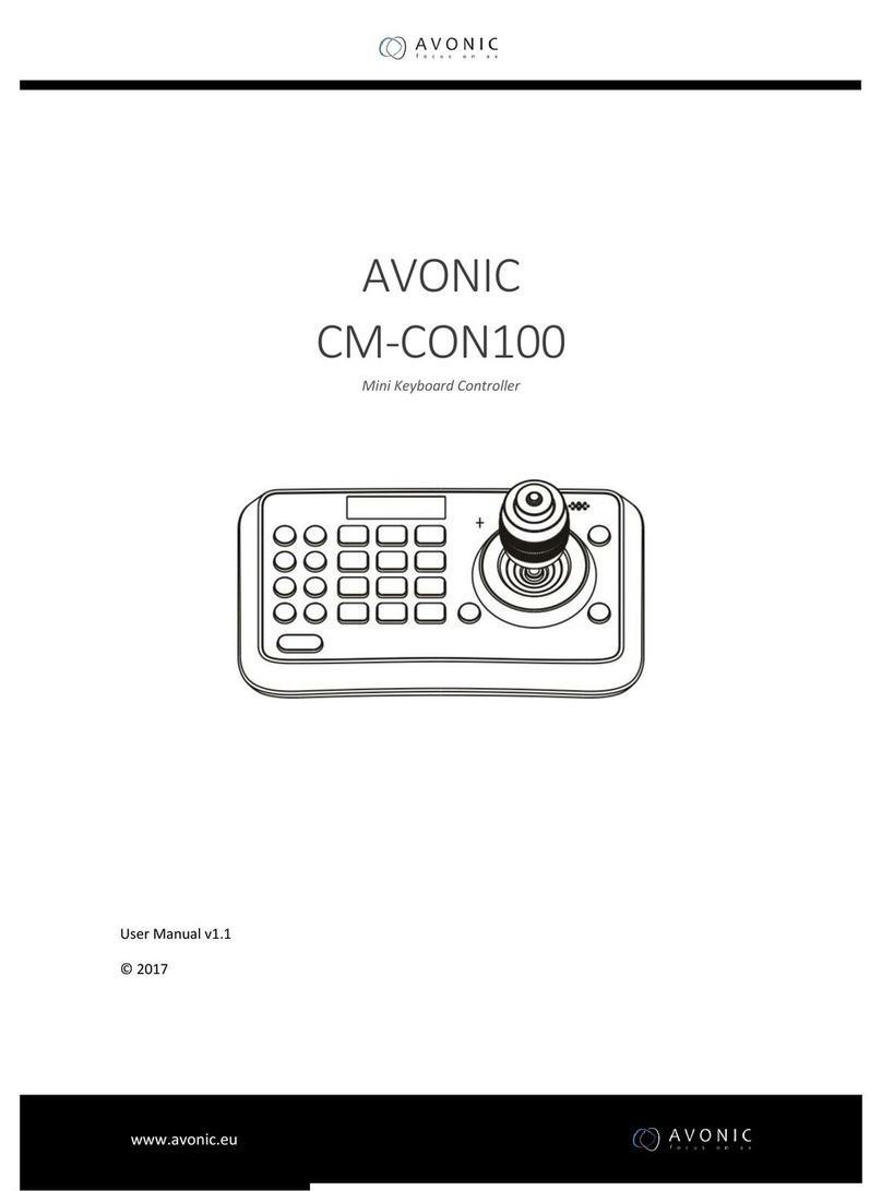
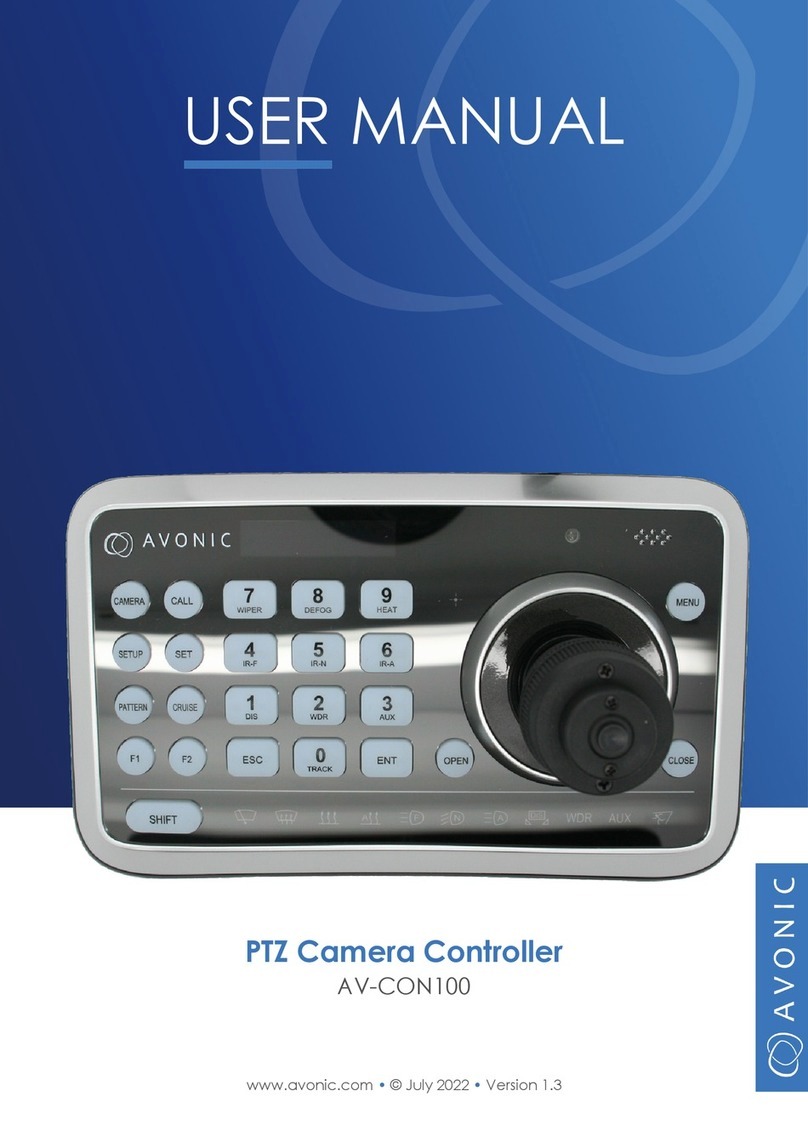
Avonic CM-CON100 User manual

User Manual | Version 1.1.1
www.avonic.com
PTZ Camera Controller
CM-CON100

22
CONTENTS
Introduction............................................................................................................................. 3
Congratulations .. .. .. .. .. .. .. .. .. .. .. .. .. .. .. .. .. .. .. .. .. .. .. .. .. .. .. .. .. .. .. .. .. .. .. .. .. .. .. .. .. .. .. .. .. .. .. .. .. .. 3
Contact. .. .. .. .. .. .. .. .. .. .. .. .. .. .. .. .. .. .. .. .. .. .. .. .. .. .. .. .. .. .. .. .. .. .. .. .. .. .. .. .. .. .. .. .. .. .. .. .. .. .. .. .. .. .. .. .. 3
Join Avonic .. .. .. .. .. .. .. .. .. .. .. .. .. .. .. .. .. .. .. .. .. .. .. .. .. .. .. .. .. .. .. .. .. .. .. .. .. .. .. .. .. .. .. .. .. .. .. .. .. .. .. .. .. .. 3
Safety Notes............................................................................................................................ 4
Package contents and Accessories ...................................................................... 6
Contents.. .. .. .. .. .. .. .. .. .. .. .. .. .. .. .. .. .. .. .. .. .. .. .. .. .. .. .. .. .. .. .. .. .. .. .. .. .. .. .. .. .. .. .. .. .. .. .. .. .. .. .. .. .. .. .. 6
Product Overview................................................................................................................ 6
Features .. .. .. .. .. .. .. .. .. .. .. .. .. .. .. .. .. .. .. .. .. .. .. .. .. .. .. .. .. .. .. .. .. .. .. .. .. .. .. .. .. .. .. .. .. .. .. .. .. .. .. .. .. .. .. .. 6
Installation ............................................................................................................................... 7
Connections .. .. .. .. .. .. .. .. .. .. .. .. .. .. .. .. .. .. .. .. .. .. .. .. .. .. .. .. .. .. .. .. .. .. .. .. .. .. .. .. .. .. .. .. .. .. .. .. .. .. .. .. .. 7
Connection Diagram. .. .. .. .. .. .. .. .. .. .. .. .. .. .. .. .. .. .. .. .. .. .. .. .. .. .. .. .. .. .. .. .. .. .. .. .. .. .. .. .. .. .. .. .. .. .. 7
VISCA network connection diagram .. .. .. .. .. .. .. .. .. .. .. .. .. .. .. .. .. .. .. .. .. .. .. .. .. .. .. .. .. .. .. .. .. .. .. 7
RS485 network connection diagram .. .. .. .. .. .. .. .. .. .. .. .. .. .. .. .. .. .. .. .. .. .. .. .. .. .. .. .. .. .. .. .. .. .. .. 9
Addressing Multiple Cameras .. .. .. .. .. .. .. .. .. .. .. .. .. .. .. .. .. .. .. .. .. .. .. .. .. .. .. .. .. .. .. .. .. .. .. .. .. .. .. .. 9
Operation Instructions..................................................................................................... 10
Non-Setup Menu.. .. .. .. .. .. .. .. .. .. .. .. .. .. .. .. .. .. .. .. .. .. .. .. .. .. .. .. .. .. .. .. .. .. .. .. .. .. .. .. .. .. .. .. .. .. .. .. .. .. 11
Setup Menu Mode.. .. .. .. .. .. .. .. .. .. .. .. .. .. .. .. .. .. .. .. .. .. .. .. .. .. .. .. .. .. .. .. .. .. .. .. .. .. .. .. .. .. .. .. .. .. .. .. .. 11
1. Camera Setting .. .. .. .. .. .. .. .. .. .. .. .. .. .. .. .. .. .. .. .. .. .. .. .. .. .. .. .. .. .. .. .. .. .. .. .. .. .. .. .. .. .. .. .. .. .. .. .. .. 12
2. Time Setting. .. .. .. .. .. .. .. .. .. .. .. .. .. .. .. .. .. .. .. .. .. .. .. .. .. .. .. .. .. .. .. .. .. .. .. .. .. .. .. .. .. .. .. .. .. .. .. .. .. .. .. 12
3. Volume Setting .. .. .. .. .. .. .. .. .. .. .. .. .. .. .. .. .. .. .. .. .. .. .. .. .. .. .. .. .. .. .. .. .. .. .. .. .. .. .. .. .. .. .. .. .. .. .. .. .. 13
4. Backlight Setting .. .. .. .. .. .. .. .. .. .. .. .. .. .. .. .. .. .. .. .. .. .. .. .. .. .. .. .. .. .. .. .. .. .. .. .. .. .. .. .. .. .. .. .. .. .. .. .. 13
5. Sleep Setting .. .. .. .. .. .. .. .. .. .. .. .. .. .. .. .. .. .. .. .. .. .. .. .. .. .. .. .. .. .. .. .. .. .. .. .. .. .. .. .. .. .. .. .. .. .. .. .. .. .. .. 13
6. PIN Setting (and what to do if the admin pin is lost) .. .. .. .. .. .. .. .. .. .. .. .. .. .. .. .. .. .. .. .. .. .. 13
7. Joystick Calibration .. .. .. .. .. .. .. .. .. .. .. .. .. .. .. .. .. .. .. .. .. .. .. .. .. .. .. .. .. .. .. .. .. .. .. .. .. .. .. .. .. .. .. .. .. .. 14
8. 10Key Custom .. .. .. .. .. .. .. .. .. .. .. .. .. .. .. .. .. .. .. .. .. .. .. .. .. .. .. .. .. .. .. .. .. .. .. .. .. .. .. .. .. .. .. .. .. .. .. .. .. .. 14
9. Speed Setting .. .. .. .. .. .. .. .. .. .. .. .. .. .. .. .. .. .. .. .. .. .. .. .. .. .. .. .. .. .. .. .. .. .. .. .. .. .. .. .. .. .. .. .. .. .. .. .. .. .. 15
10. Default Setup .. .. .. .. .. .. .. .. .. .. .. .. .. .. .. .. .. .. .. .. .. .. .. .. .. .. .. .. .. .. .. .. .. .. .. .. .. .. .. .. .. .. .. .. .. .. .. .. .. .. 15
11. Information .. .. .. .. .. .. .. .. .. .. .. .. .. .. .. .. .. .. .. .. .. .. .. .. .. .. .. .. .. .. .. .. .. .. .. .. .. .. .. .. .. .. .. .. .. .. .. .. .. .. .. .. 15
OSD Menu.. .. .. .. .. .. .. .. .. .. .. .. .. .. .. .. .. .. .. .. .. .. .. .. .. .. .. .. .. .. .. .. .. .. .. .. .. .. .. .. .. .. .. .. .. .. .. .. .. .. .. .. .. .. .. 15
Maintenance .......................................................................................................................... 16
Controller Maintenance. .. .. .. .. .. .. .. .. .. .. .. .. .. .. .. .. .. .. .. .. .. .. .. .. .. .. .. .. .. .. .. .. .. .. .. .. .. .. .. .. .. .. .. .. 16
Unauthorized Use .. .. .. .. .. .. .. .. .. .. .. .. .. .. .. .. .. .. .. .. .. .. .. .. .. .. .. .. .. .. .. .. .. .. .. .. .. .. .. .. .. .. .. .. .. .. .. .. .. 16
Troubleshooting................................................................................................................... 16
General advise .. .. .. .. .. .. .. .. .. .. .. .. .. .. .. .. .. .. .. .. .. .. .. .. .. .. .. .. .. .. .. .. .. .. .. .. .. .. .. .. .. .. .. .. .. .. .. .. .. .. .. 16
Power Issues.. .. .. .. .. .. .. .. .. .. .. .. .. .. .. .. .. .. .. .. .. .. .. .. .. .. .. .. .. .. .. .. .. .. .. .. .. .. .. .. .. .. .. .. .. .. .. .. .. .. .. .. .. 16
Serial functionality issues. .. .. .. .. .. .. .. .. .. .. .. .. .. .. .. .. .. .. .. .. .. .. .. .. .. .. .. .. .. .. .. .. .. .. .. .. .. .. .. .. .. .. .. 16
www.avonic.com
Back to top

3www.avonic.com
www.Facebook.com/
avonicPTZ
INTRODUCTION
Thank you for your Avonic purchase. Before operating this product, please read the manual thoroughly and
retain it for future reference. The manual can be downloaded on www.avonic.com. Save this manual for future
reference.
CONTACT
For any questions or suggestions, contact your reseller or the local distributor of Avonic. Find the local distri-
butor on the website of Avonic. For the most recent version of the manual or datasheet, look at the Avonic
website: www.avonic.com.
JOIN AVONIC
www.Linkedin.com/company/
avonic
www.twitter.com/
avonic
Back to top

4www.avonic.com
SAFETY NOTES
Important safety information
WARNING: Failure to follow these safety instructions could result in fire, electric shock, injury, or damage to
this Product or other property. Read all the safety information below before using
this Product.
WARNING: Before operating this product, please read the manual thoroughly and retain it for future
reference. The manual can be downloaded on www.avonic.com.
Handling
Handle this Product with care. It is made of metal, glass, and plastic and has sensitive electronic components
inside. this Product can be damaged if dropped, burned, punctured, or crushed, or if it comes in contact with
liquid. If you suspect damage to this Product, discontinue use of this Product, as it may cause overheating or
injury.
Installation
Set up this Product on a hard, stable surface. Make sure to make use of a safety loop or drop protection that is
capable of preventing the Product from falling. Never install a product above persons to prevent any risk on
injuries when it falls down.
WARNING: In order to maintain adequate ventilation, do not install or place this unit in a bookcase, built-in
cabinet or any other confined space. To prevent risk of electric shock or fire hazard due to overheating, ensure
that curtains and any other materials do not obstruct the ventilation.
WARNING: Check the installation at least once a year. An improper installation could cause the unit to fall
off resulting in personal injury.
Repairing
Don’t open this Product and don’t attempt to repair this Product yourself. Disassembling this Product may
damage it or may cause injury to you. If this Product is damaged, malfunctions, or comes in contact with liquid,
contact Avonic or an Avonic Authorized Service Provider. Repairs by service providers other than Avonic or an
Avonic Authorized Service Provider may not involve the use of Avonic genuine parts and may affect the safety
and functionality of the device. You can find more information about repairs and service at www.avonic.com.
Power
Power this Product with the included cable and power adapter. Other adapters may not meet applicable
safety standards, and connecting with such adapters could pose a risk of death or injury.
WARNING: Using damaged cables, or using the Product when moisture is present, can cause fire, electric
shock, injury, or damage to this Product or other property. When you power this Product, make sure the cable is
fully inserted into the power adapter before you plug the adapter into a power outlet. It’s important to keep this
Product, the cable, and the power adapter in a well-ventilated area when in use.
Back to top

5www.avonic.com
Power adapter
To operate the Avonic power adapter safely and reduce the possibility of heat-related injury or damage, plug
the power adapter directly into a power outlet. Don’t use the power adapter in wet locations, and don’t connect
or disconnect the power adapter with wet hands. Stop using the power adapter and any cables if any of the
following conditions exist:
• The power adapter plug or prongs are damaged.
• The cable becomes frayed or otherwise damaged.
• The power adapter is exposed to excessive moisture, or liquid is spilled into the power adapter.
• The power adapter has been dropped, and its enclosure is damaged.
Intended use
This Product is intended to control PTZ camera’s, shall not be used in the residential area and shall only be
installed and operated by experienced technicians.
Not a medical device
This Product is not a medical device and should not be used as a substitute for professional medical judgment.
It is not designed or intended for use in the diagnosis of disease or other conditions, or in the cure, mitigation,
treatment, or prevention of any condition or disease. Please consult your healthcare provider
prior to making any decisions related to your health.
Explosive and other atmospheric conditions
Using this Product in any area with a potentially explosive atmosphere, such as areas where the air contains
high levels of flammable chemicals, vapours, or particles (such as grain, dust, or metal powders), may be
hazardous. Exposing this Product to environments having high concentrations of industrial chemicals,
including near evaporating liquified gasses such as helium, may damage or impair this Product functionality.
Obey all signs and instructions.
High-consequence activities
This device is not intended for use where the failure of the device could lead to death, personal injury, or severe
environmental damage.
Back to top

6
Number Quantity Description Avonic SKU
1 1 pc PTZ Camera Keyboard Controller CM-CON100
2 1 pc Power Supply 12V/A CM-CON100-PSU
Contents
PACKAGE CONTENTS AND ACCESSORIES
• Number of presets: With this compact controller, it is possible to control up to 255 cameras
and use up to 255 presets.
• Connection: Easy to connect with RS232, RS485
• Control: Every setting of the camera can be controlled by accessing the OSD of the
camera through the controller.
• Direct control Pan, Tilt, Zoom and Focus.
The Avonic CM-CON100 is a compact PTZ camera controller. With this controller it is possible to
control up to 255 camera’s and using up to 255 presets.
The controller supports the Visca, Pelco-D and Pelco-P protocol and can be connected with
RS232/485. The Avonic CM-CON100 is therefore compatible with the Avonic camera’s as well with
other brands that support these protocols.
Switch easily between auto and manual focus, save and load presets, and connect multiple
controllers to multiple camera’s.
Features
PRODUCT OVERVIEW
www.avonic.com
1
2
Note that a cable with RS485 and RS232 connection is attached to the controller, but not pictured below.
Back to top

7
Connections
INSTALLATION
www.avonic.com
Button Functionality Operation
1 OLED screen Displays status of current operation
2 CALL Call a preset Preset number + CALL key
3 CAMERA Switch camera’s Camera number + CAMERA Key
4 SET Set or delete a preset Preset number + SET key (Short press SET key; long
press to delete).
5 SETUP Change keyboard settings
6 CRUISE Make presets. No other functionality
7 PATTERN Make presets. No other functionality
8 F1, F2 Switch autofocus/ manual focus
(See also no. 18.) - Press F2 for Manual Focus ON
- Press F1 for Autofocus ON (switch back to Zoom)
9 SHIFT Extension key for special functions Press SHIFT + another key (see no. 5 page 12)
10 ESC EXIT / delete a wrong insert in Setup
Menu See page 12 and step 4 page 14
11 0~9 (Numbers) Input numbers SET/CALL functionality, Camera ID and address.
See page 11 and 12.
12 ENT Confirm menu setting
13 OPEN Actives IRIS open of the camera
Confirm button in OSD menu
14 Joystick Pan, Tilt, Zoom and Focus - Move the joystick to pan and tilt the camera.
- Twist the joystick to zoom in and out
- Press the joystick button to switch to Focus
(See no. 18)
15 CLOSE Close IRIS of the camera
16 Status Display area No functionality. Only lights on the
display will go ON and OFF
- Press SHIFT + Number to light up an icon.
- Press SHIFT + Number again to set it OFF.
17 MENU Enter camera (OSD) menu
Make presets in Setup menu
18 Zoom / Focus Switch Key.
(See also no. 8.)
Switch Zoom/ Focus - Press Joystick button to switch to focus and
twitch joystick right and left to focus in and out.
- Press button again to switch to Zoom.
Back to top

8
The controller has 3 wires:
• Power with female JEITA connector
• RS232 with 3 pin Terminal Strip
• RS485 with 2 pin Terminal Strip
Maximum distance for RS232 is about 15 meters. Maximum distance for RS485 is about 1200 meters.
Connection Diagram
RS485 Cable
RS232 Cable
Power (DC12V)
Power Supply
PTZ Camera
PTZ Camera
When connecting multiple cameras through RS-232, use daisy chaining network architecture. Max cable
length for RS-232 is 10-15m.
VISCA network connection diagram
Controller
Controller
Camera
In Out
RS-232 RS-232 RS-232
In Out In Out
Camera Camera
www.avonic.com
Back to top

9
To connect multiple cameras by RS485, the cameras are attached to a 2-wire twisted pair bus (max length
1200m) that is terminated at both ends with a 120 Ω impedance resistor. The maximum distance from the bus
to the camera or controller is 5m.
In case more cameras are connected to the controller, each camera needs to be addressed the right way to a
camera number of the controller.
The following settings need to match in both camera and controller:
1. Protocol (VISCA, PELCO-p or PELCO-d)
2. Camera address number (1, 2 or n)
3. Communication settings as baud rate (9600), parity, etc.
RS485 network connection diagram
Addressing Multiple Cameras
www.avonic.com
See page 12 (Camera Settings) for more information. The following section of this manual describes how to set
up the controller.
Back to top

10www.avonic.com
OPERATION INSTRUCTIONS
This chapter will explain the operation instructions. If you have connected the RS485 cable to your camera
(see previous chapter) the CON100 will start automatically. When the CON100 is for the first time ON, you will
see that it will display the User PIN.
Press to fill in the pin. The initial pin is “111111”.
Pin Error: When “USER PIN: ERROR” shows on screen, it indicates wrong pin was set. Enter correct pin to go to
the next step.
Pin Correct: Screen shows “1” camera icon and default camera number. If there is no operation, after 5
seconds the screen will display the current time. If still no operations, the controller will enter sleepmode
(30sec, 1min, 5min, 10min, 30 min or 60 min.)
After the PIN is correctly entered, you can operate the CON100. The CON100 has three different “Menu’s”:
• Non-Setup menu: to control a camera while filming
• Setup menu: to change the settings of the CON100
• OSD menu: to control and change the camera settings itself
See also the picture below. Note that it is very easy to confuse both menu’s! So keep always in mind in
which menu you are. See page 12 for the SETUP menu and page 11 for the NON-Setup Menu.
Back to top

11www.avonic.com
NON-Setup Menu
SET/ CALL Preset Position
With the CON100 it is possible to set the camera in a desired position as a preset. You can call that preset
when you need it.
Set preset*
1. Move the joystick to set the camera in the desired position.
2. Press short number 1 button (or another number button between 0 - 255).
3. Press short the to set the preset.
CALL preset*
1. Press number 1 button (or another number button between 0 - 255).
2. Press the to call the preset. Camera moves automatically to the postion of that preset number.
* Note also that it is possible to easily confuse the Preset/ CALL functionality with setting up camera
(protocol) Address and ID number! (see page 12) Keep in mind in which feature and menu you are.
Delete Preset Position
To delete a preset do the following:
1. Press the number button of the preset you want to delete.
2. Wait untill the camera moves to the position of that preset number.
3. Press again the number button of the preset you want to delete.
4. Press long the SET number button.
5. [CLR PRESET:] shows shortly on the screen of the controller.
6. The Preset is now deleted and empty.
How to switch to another camera
See page 12 how to set an ID for your camera, if you have multiple camera’s to control with the CON100.
1. Press in the NON-Setup Menu camera number
2. Press the camera button
PTZ controls
Move the Joystick up, down, left and right (1) to control the camera. Turn the joystick clockwise to zoom
in (2) and anti-clockwise to zoom out (3). The button on the joystick is for switching between zoom and
focus (3). See pictures below:
1 2 3
Zoom and Focus
It is possible to switch to Focus mode in two different ways: Using the Joystick button (see picture 3
above), or using the F2 button. Press F2 to switch to Focus mode and twist the joystick left and right to
focus. Press F1 to switch back to Zoom mode. Note that you need to twist the joystick again to autofocus
the camera and zoom out.
Back to top

12www.avonic.com
Setup Menu
Press to enter the Setup menu. Fill in the “ADMIN PIN”. The initial ADMIN PIN is “111111”.
The camera setting screen will show up. Use the joystick up and down to scroll through the menu features.
Move the stick to the right to enter the menu features and move the joystick to the left to leave the menu
features. It is also possible to use the button to leave a menu feature, or delete a wrong insert. See the
picture below:
Setting Functionality Operation
Camera ID** Sets unique Camera Identification number 1. Move the joystick to the right to enter the Camera Setting
menu. The : appear on the screen. This will set the
Camera ID. Press 1 - 255 to set the ID and press
Protocol Setting Sets camera control protocol 2. Move to change the protocol setting (VISCA,
VISCA DC, PELCO D, PELCO P) and press
Baud Rate Sets the rate at which information is send
between controller and camera
3. Move to change the Baud Rate (2400, 4800, 9600,
19200, 38400) and press
Address** Sets a specific (protocol) address for a
camera.
4. Standard “‘1”, but you can set it between 1 - 255.
Increment* Batches program camera’s in the system
with the same baudrate, protocol for
multiple camera’s. So you can control
multiple camera’s at the same time.
5. After you set the Camera Address, press SHIFT to enter
the increment menu. Input a number within 1~20,
press to confirm.
1. Camera Setting
* Note that the address increment between to sequental camera’s. For example, if the current camera address
is 1 and the increment is 2, then the next camera address is 3.
** Note also that it is very easy to confuse (Protocol) address, Camera ID and the SET/CALL functionality! (see page 11)
Keep always in mind in which feature and menu you are making changes.
2. Time Setting
1. Move the joystick down and right to enter the Time Setting menu.
2. Move to change the numbers and to change hours, minutes and seconds.
3. Press to save the time.
Time Setting - Hours / Minutes / Seconds
Back to top

13www.avonic.com
3. Volume Setting
Move the joystick up to increase and down to decrease the volume (0 - 6), or set it OFF. Press
to save the volume.
Volume Setting - 0 - 6
- OFF
4. Backlight Setting
The backlight setting will lighten the buttons of the CON100 to help to see the buttons in dark area’s. Move the
joystick up and down to change the backlight mode (AUTO, ON, OFF) and press to save the setting.
Backlight Setting - AUTO
- ON
- OFF
5. Sleep Setting
The sleep setting will set the time before the CON100 will fall asleep.
1. Move the joystick up and down to change the time (Off, 30 seconds, 1 minute, 5 minutes, 10 minutes, 30
and 60 minutes).
2. Press to save the time.
3. Press a (random) button or move the joystick to make the CON100 active again.
Sleep Setting - OFF
- 30 seconds
- 1 / 5 / 10 / 30 / 60 Minutes
6. PIN Setting (and what to do if the PIN is lost)
This will set the PIN. Move the joystick up and down to change between the USER or the ADMIN
(administrator). Press to save. The controller now asks for the old PIN. Type the old PIN by using the
number buttons and press ENT to confirm. Enter now the new PIN and confirm this by pressing the ENT button.
For the initial PIN see page 10.
If the PIN has been changed and is lost, use the following mastercode to regain access to the
CON-100: 7 7 8 8 9 6
Note: In non-setup menu status, quickly lock function can be realized by simply pressing SHIFT + ENT . “USER
PIN”or “ADMIN PIN” is required for operating the controller again.
PIN Setting - USER
- ADMIN
Back to top

14www.avonic.com
7. Joystick Calibration
After a long time of use the joystick may need calibration. See the table below how to do it.
Funtionality Operation
Pan Left Move to the limit and press at the same time.
Pan Right Move to the limit and press at the same time.
Tilt Up Move to the limit and press at the same time.
Tilt Down Move to the limit and press at the same time.
Zoom Tele Move clockwise to the limit and press at the same time.
Zoom Wide Move anti-clockwise to the limit and press at the same time.
Free State Press to confirm.
Save/Cancel Move the to swich between SAVE and CANCEL. Press to save or cancel.
8. Key Custom
Key custom is used to make extra presets for the controller next to the SET/CALL function (see page 11).
Unfortunatily, you cannot make Patterns or use the Cruise functionality with the CON100. Note that this
functionality is unreliable. It will not always work. Use as much as you can the SET/ CALL functionality.
Step Operation
1 Move in NON-Setup Menu the joystick to set the camera in the desired position.
2 Move in Setup Menu to Key Custom and open te menu. Screen Menu preset shows up.
3 Press PATTERN, CRUISE or MENU Button (see picture above). The corresponding Menu opens
4 * Press the preset number** (0-255) to set and press to confirm. Press ESC if you pressed the
wrong number.
5 Screen Changed to: appears. Move the joystick to the left to leave the menu
6 In Non-Setup Menu press the number you just made a preset for and press Pattern, Cruise or Menu
button. The camera will automatically move in the desired position.
* Do not make a preset with the same number using the SET button and the PATTERN, CRUISE or MENU button! It is
possible that the preset made using the PATTERN, CRUISE or MENU button will be overridden by the CON100 and will not
work. For a correct functionality of the presets, stick always to 255 presets and do not make for example two presets
number 2, 3, 4, 5 etc !
** Note also that it is possible to easily confuse the preset functionality with setting up camera (protocol ) Address and
ID number! (see page 12) Keep always in mind in which feature and menu you are.
Back to top

15www.avonic.com
9. Speed Setting
Speed Setting sets the speed to which the camera will respond when you move the camera by using the
joystick. Move to change the setting between Low, Middle and High. Press to save the setting.
10. Default Setup
Restores the Keyboard setting to factory Default.
1. Move to open the Default Setup.
2. Move to change between <YES> or NO.
3. Press to save the setting.
11. Information
The information display shows the firmware version number. Move to open the menu.
Speed Setting - Low
- Middle
- High
Default Setup - <YES> NO
Information - VERSION
OSD Menu
With the menu button next to the joystick, you can open the OSD menu of the camera to make changes in
the settings of the camera itself. If you are using an Avonic camera in combination with the CON100, you can
download our camera manual on our website to read about the functionality of the OSD menu. If you are
using a third party camera, please refer to the manual or instruction of this third party camera.
Follow these instructions to navigate through the OSD menu:
1. Press the Menu button to open the OSD Menu
2. Move the joystick up and down to scroll through the menu
3. Press OPEN to enter a menu feature
4. Move the joystick left and right to change the settings within a menu feature
5. Press CLOSE or ESC to leave a menu feature or the OSD menu itself.
5
3
1
Back to top

16
Unauthorized Use
Controller Maintenance
• Don’t operate close to powerful electromagnetic radiation, such as TV or radio
transmitters, etc.
• If the controller will not be used for a long time, please turn off the power switch,
disconnect AC power cord of AC adaptor to the outlet.
• Use soft cloth or tissue to clean the display.
• Please use a soft dry cloth to clean the controller. If the device is very dirty, clean it
with diluted neuter detergent. Do not use any type of solvents, which may damage
the surface.
• Turn the controller off and on again and check if the problem persists.
• Restore to Factory Default (Setup menu option 10)
• No display and no buttons light
- Check the net power
- Check the power supply
- Check if the serial cable is attached to a camera
General advise
Power Issues
TROUBLESHOOTING
MAINTENANCE
• Cannot control camera
- Check serial cable(s) and the RJ45 termination
- Reset to factory default
Serial functionality issues
www.avonic.com
Back to top
Other manuals for CM-CON100
5
Table of contents
Other Avonic Controllers manuals

Avonic
Avonic CM-CON100 User manual

Avonic
Avonic CD500 User manual

Avonic
Avonic AV-CON100 User manual

Avonic
Avonic AV-CON300 User manual

Avonic
Avonic AV-CON300-IP User manual

Avonic
Avonic CD500 User manual

Avonic
Avonic AV-CON300 User manual

Avonic
Avonic CM-CON100 User manual

Avonic
Avonic AV-CON300 User manual

Avonic
Avonic AV-CON300-IP User manual
Popular Controllers manuals by other brands

CLA-VAL
CLA-VAL 130VC-2 Installation operation & maintenance

Frigicoll
Frigicoll Kaysun KWF 140 ACS owner's manual

VAL
VAL VLC-2430-4 Operation manual

Schmidlin
Schmidlin TOUCH CONTROL Instructions for use

LEYBOLD
LEYBOLD GRAPHIX ONE instruction manual

Mitsubishi Electric
Mitsubishi Electric MELSEC Q Series user manual