AVS Electronics BM 60 M User manual

- 1 -
IST0638V1/0
MICROWAVE BEAMS
FOR INDOOR AND OUTDOOR USE
BM 60 M
BM 120 M
BM 200 M
BM60M WS
AVS ELECTRONICS
Curtarolo (Padova) Italy
www.avselectronics.com
A COMPANY WITH
CERTIFIED SYSTEM
OF QUALITY
ISO9001

- 2 -
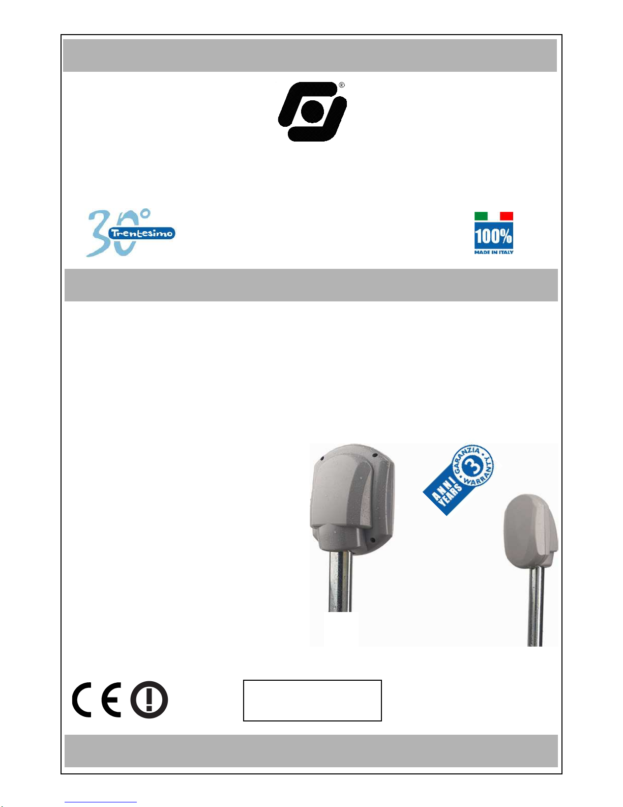
The product is in conformity to the CE Directive for electromagnetic compatibility
Supplying must come from a very low security-tension circuit, featuring a limited-power
source protected by fuse.
THE INSTALLATION MUST BE EXECUTED BY QUALIFIED PERSONNEL
Index
Chapter 1: General Description .................................................................................pag. 3
Compatibility with existing models ....................................................................pag. 3
Filter of selection and compensation .................................................................pag. 3
Detection Area ......................................................................................................pag. 3
Chapter 2: Transmitter................................................................................................pag. 3
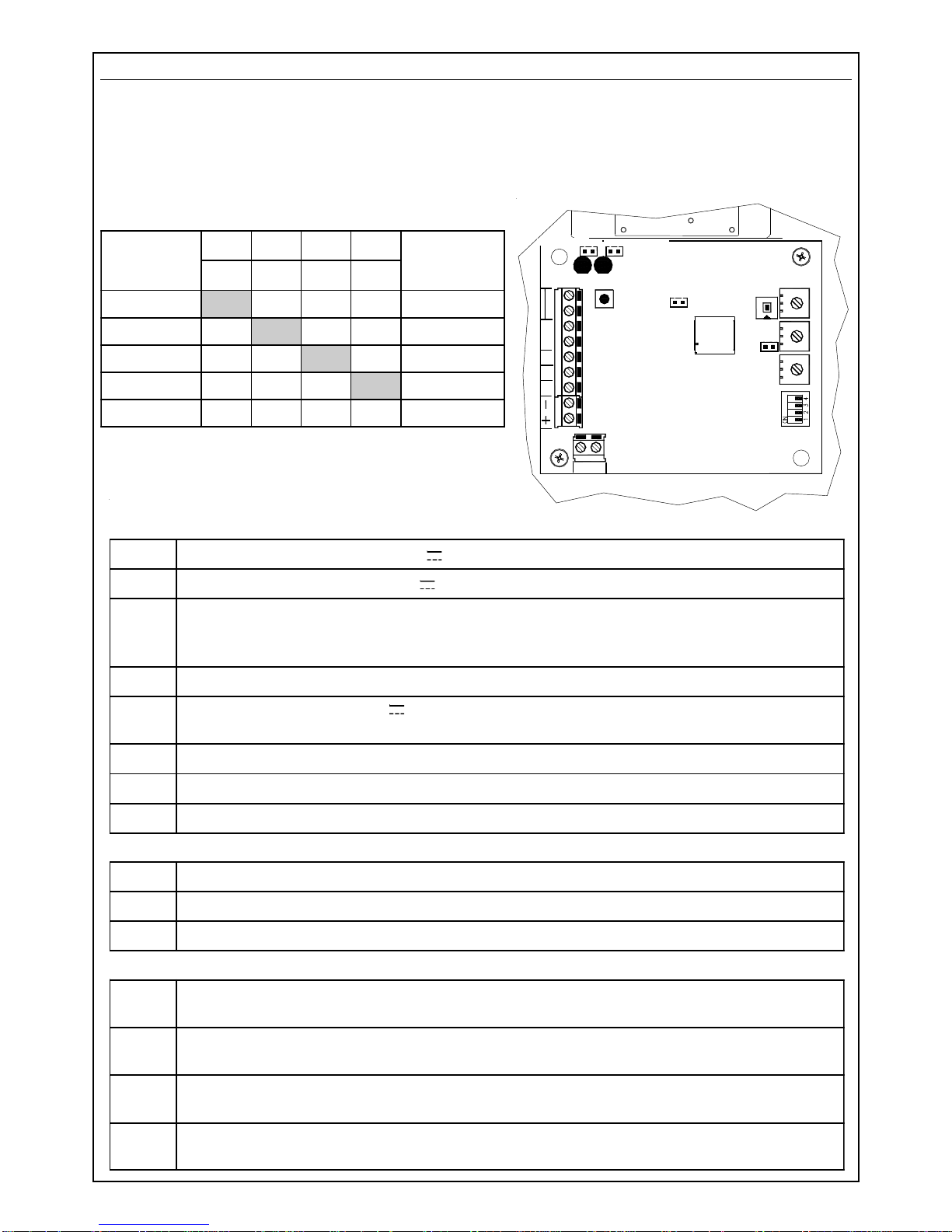
Chapter 3: receiver of hard-wired systems BM60M, BM120M, BM200M................pag. 4
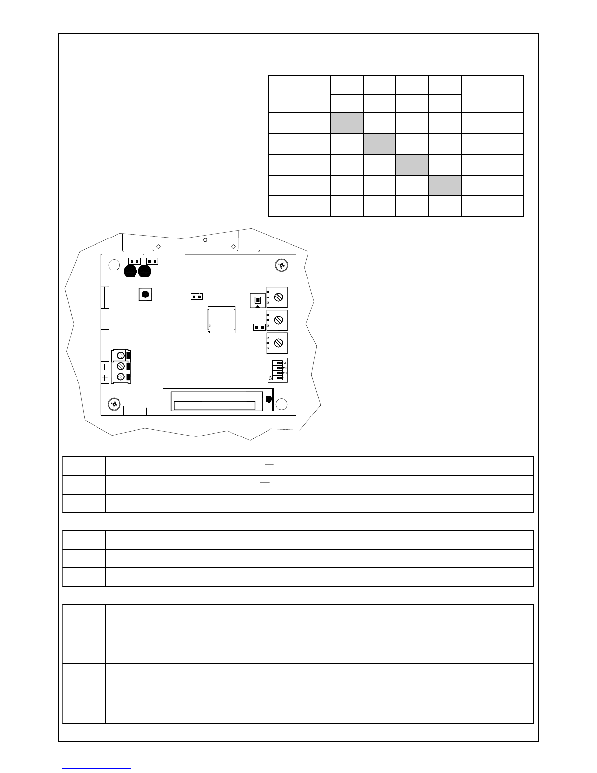
Chapter 4: Receiver of the wireless system BM60M WS.........................................pag. 5
Chapter 5: Description of working ............................................................................pag. 6
Working.................................................................................................................pag. 6
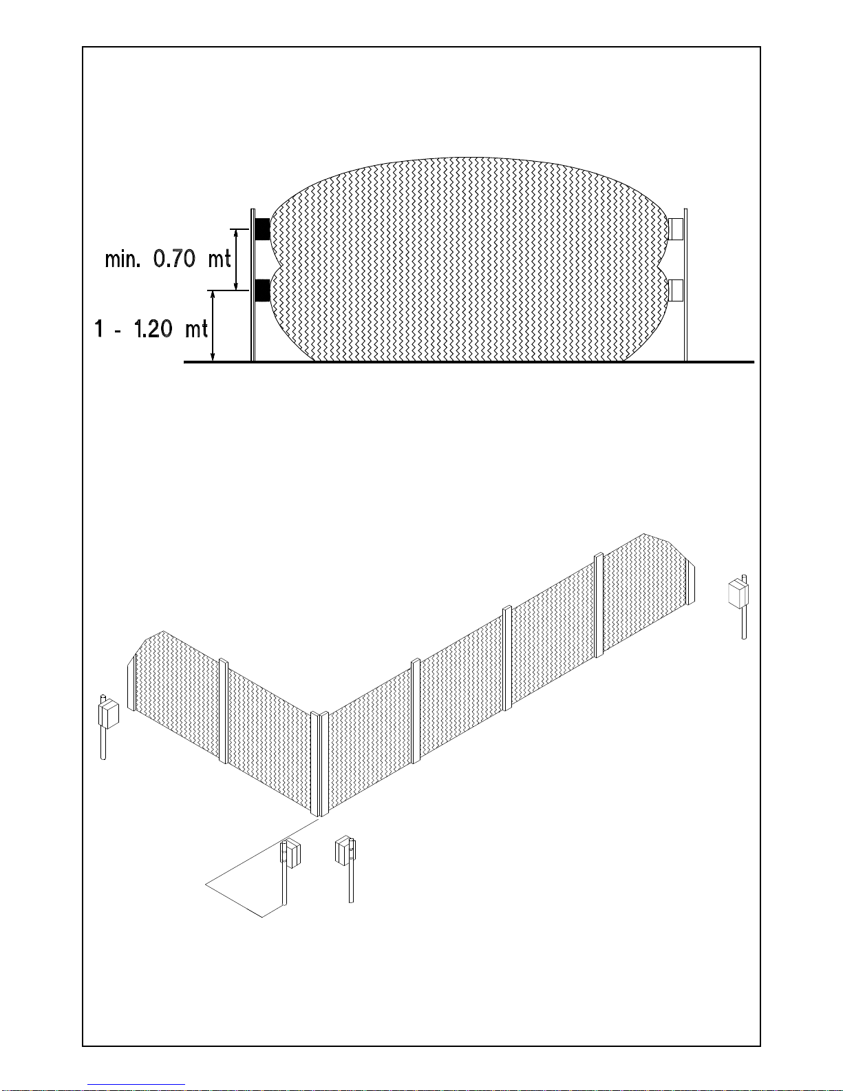
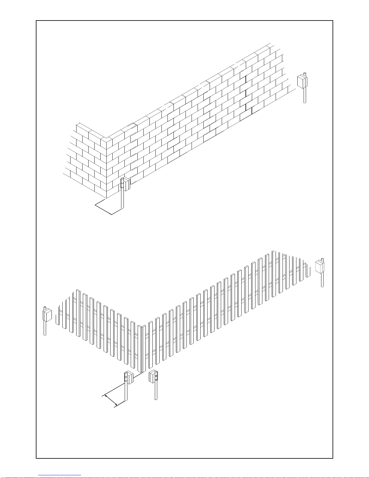
Chapter 6 : Positioning of the beams........................................................................pag. 7
Chapter 7: Advice for installation ............................................................................pag. 13
Chapter 8: Installation of the transmitter in the hard-wired system.....................pag. 14
Chapter 9: Installation of receiver in the hard-wired system ................................pag. 14
General Warning for the hard-wired system....................................................pag. 14
Chapter 10: Installation of transmitter in the wireless system .............................pag. 14
Chapter 11: Installation of the receiver in the wireless system............................pag. 14
General Warning for wireless system ..............................................................pag. 14
Chapter 12: Adjustments..........................................................................................pag. 15
Chapter 13: Measurements of the signal by oscilloscope ....................................pag. 16
Chapter 14: Sensitivity Adjustment .........................................................................pag. 17
Chapter 15: Kit TERM (optional) Resistence fo inside heating.............................pag. 18
Chapter 16: Kit AMP (optional) Anti-removal..........................................................pag. 18
Chapter 17: Disqualification (Important Warning) .................................................pag. 19
Chapter 18: Additional supply unit for BM60M WS................................................pag. 19
Chapter 19: BR100 Kit and LCD W (optional) signal remoting-device .................pag. 20
Chapter 20: Optional Brackets.................................................................................pag. 21
Information in conformity to the Directive 1999/5/CEE for model BM_M.............pag. 22
Information in conformity to the Directive 1999/5/CEE for model BM60M WS....pag. 23
Technical Characteristics.........................................................................................pag. 24

- 3 -
TAMPER
B A TT
S1
PB1
SW1
LED
LED
OFF
MICROWAVE BEAM
ModelsBM60M, BM120M, BM200M and BM60M WS aremicrowaveintrusiondetectionsystems,
whose principle of working is the “field-interruption”.Thanks to the microprocessor managing the
signals, they are the ideal instruments for protecting big surfaces, both indoor and outdoor, thus
granting a high security standard.
Chapter 1: General Description
The system is made by a Transmitter and a Receiver which must be installed as a couple,
choosing the same working frequency among the 5 available, in both units (tx and rx) ,
through SW1 (4 dip-switch module) on board.
Compatibility with existing models
In case of replacement, choose the same frequency on the beam to be replaced (F1 by F1, F3 by
F3 etc.). In order to identify the corresponding frequency, use the chart “BEAMS CHANNELS”
Filter of selection and compensation
Any receiver is equipped with a selection filter choosing only the frequency of its channel and
rejecting the others, thus not making possible the elusion of the beam in case of use of a false
transmitter. Special self-adjusting and signal-elaboration circuits have been used in the receiver
for automatic compensation of temperature variations.
Detection Area
The shape of the irradiation area is very well defined and this allows a higher possibility of
detection and a reduction of false alarms risk.
These beams are manufactured exclusively with solid-state components and are tropicalyzed in
order to obtain a very good seal against weather conditions.
Chapter 2: Transmitter
The transmitter is made of a planar microwave emitting a narrow and directional higly-stable low
power beam.
A4-dip-switch for setting workingfrequency is on board.
Check that the transmitter working frequency set is
the same as in the receiver coupled
-V21evitagengniylppus
+V21evitisopgniylppus
TT gnineporotcetedtsiaganoitcetorproftuptuo.c.n
1S desolc nepo delbanedeLgniylppus delbasiddeLgniylppus
MMB SLENNAHC PID PID PID PID SULPQMB SLENNAHC
1234
1F NO FFO FFO FFO DLOG
2F FFO NO FFO FFO EULB
3F FFO FFO NO FFO REVLIS
4F FFO FFO FFO NO WOLLEY
5F FFO FFO FFO FFO -

- 4 -
Chapter 3: receiver of hard-wired systems BM60M, BM120M, BM200M
The receiver is made of a high-sensitivity electronic circuit coupled to the antenna; it detects the
signaltransmitted in itschannelandmeasuresits intensity.Specialtechniquesofsignal-elaboration
allow to compensate the variations in the sorroundings and to minimize the effect of possible
perturbations due to small animals or birds.
A 4 dip-switch is on board for setting working frequency
Check that the working frequency of the receiver is
the same as set in the transmitter coupled.
draoBlanimreT
-V21evitagengniylppus
+V21evitisopgniylppus
DAm05(evitagendezirotsisnartasevigti;langisnoitacifilauqsiDfotuptuo rettimsnartehtfolangisehtesacnisliafevitagensihT.noitidnocteiuqgnirud).xam ces03nihtiwdeviecertonsi
PT deviecerlangisehtfonoitazilausivroftnioPtseTfotuptuoevitisop
Bmralaeht,lanimretsihtotevitisopagnivig;yb-dnatsrofV21:tupnievitisop noitidnocteiuqniskcolbyaler
CN/C yalermralafoegnahcxe..c.n
TT gnineporotcetedtsniaganoitcetorproftuptuo.c.n
BA lenapetomerfonoitcennocrofroodlaires
remmirT
LEVEL deviecerlangisehtgnitsujdarofremmirt
.SNES esiwkcolcgninrutybsesaercniti;ytivitisnesgnitsujdarofremmirt
.PMOC esiwkcolc-retnuocgninrutybsesaercniti;noitasnepmocgnitsujdarofremmirt
srepmuJ
1S desolc nepo delbane,evaworcimfoytilauq-langisfodeLneerg delbasid,evaworcimfoytilauq-langisfodeLneerg tluafed
2S desolc nepo delbane,gnillangismralafodeLder delbasid,gnillangismralafodeLder tluafed
FFO PMOC desolc nepo dedulcnitiucricnoitasnepmoc dedulcxetiucricnoitasnepmoc tluafed
GAC desolc desolcniamertsumrepmujsiht
B
C
A
TPB D
LED
VERDE
TAMPER
TNC
T
TAMPER
S1 : OFF LED VERDE
LED
ROSSO
S2 : OFF LED ROSSO
CAG
SENS.
OFF COMP.
SW1 COMP.
TEST
CAG
LEVEL
MMB SLENNAHC PID PID PID PID SULPQMB SLENNAHC
1234
1F NO FFO FFO FFO DLOG
2F FFO NO FFO FFO EULB
3F FFO FFO NO FFO REVLIS
4F FFO FFO FFO NO WOLLEY
5F FFO FFO FFO FFO -
S1: OFF GREEN LED S2: OFF RED LED
GREEN LED RED LED

- 5 -
M_MB SLENNAHC PID PID PID PID SSERDDA
1234
1F NO FFO FFO FFO 1
2F FFO NO FFO FFO 2
3F FFO FFO NO FFO 3
4F FFO FFO FFO NO 4
5F FFO FFO FFO FFO 5
Chapter 4: Receiver of the wireless system BM60M WS
The receiver has the same characteristics as the hard-wired models, with a few differences:
•the 4-ways dip-switch on board
adjusts both working frequency
and the zone address set. If, e.g.,
the beam is addressed on
frequencyF2(dip1,3,4inOFFand
dip 2 in ON), it is automatically
acquired as detector 2. It is not
possible to select the working
frequency and the zone address
in the control panel, in a sepa-
rate way.
•theterminalson board arethesupplying
(+ and -) an the signal reading (TP)
•the alarm transmission occurs for both
movementdetectioninside apatternand
protracted absence of the signal
received (disqualification): the restore
transmissionoccursafew seconds after
the signal is restored in the limits pre-
set.
Check that the working frequency of
the receiver is the same as the
frequency set on the transmitter
coupled.
B
C
A
TPB D
LED
VERDE
TAMPER
TNC
T
TAMPER
OFF LED VERDE
LED
ROSSO
OFF LED ROSSO
CAG
SENS.
OFF COMP.
SW1 COMP.
TEST
CAG
LEVEL
LED
TX
S1: OFF LED VERDE S2: OFF LED ROSSO
S1: OFF GREEN LED S2: OFF RED LED
GREEN LED RED LED
draoBlanimreT
-V21evitagengniylppus
+V21evitisopgniylppus
PT deviecerlangisehtfonoitazilausivroftnioPtseTfotuptuoevitisop
remmirT
LEVEL deviecerlangisehtgnitsujdarofremmirt
.SNES esiwkcolcgninrutybsesaercniti;ytivitisnesgnitsujdarofremmirt
.PMOC esiwkcolc-retnuocgninrutybsesaercniti;noitasnepmocgnitsujdarofremmirt
srepmuJ
1S desolc nepo delbane,evaworcimfoytilauq-langisfodeLneerg delbasid,evaworcimfoytilauq-langisfodeLneerg tluafed
2S desolc nepo delbane,gnillangismralafodeLder delbasid,gnillangismralafodeLder tluafed
FFO PMOC desolc nepo dedulcnitiucricnoitasnepmoc dedulcxetiucricnoitasnepmoc tluafed
GAC desolc desolcniamertsumrepmujsiht

- 6 -
1 - 1,2 mt
BM60M e BM60M WS : max 60 meters
BM120M : max 120 meters
BM200M : max 200 meters
3 meters 3 meters
The sensitive zone shown in the drawings is to
betakeninto consideration, asabigtarget.
Overpassing this area might cause the
same perturbations as a small body
passing the alarm area, that’s to say might
cause false alarms.
BM60M - BM60M WS
6,5 meters BM120M
10 meters BM200M
16 meters
BM60M - BM60M WS
2 meters
BM120M - BM200M
3 meters
BM60M - BM60M WS 1,2 meters
BM120M 3 meters
BM200M 4 meters
Alarm zone
Sensitive zone Sensitive zone
Chapter 5: Description of working
The two units (transmitter: TX and receiver: RX) must be positioned facing each other at the two
endsofthe distance toprotect.Be aware that the nature of the ground underneath, or special
weather conditions might affect the real range.
Working
The transmitter emits a modulated microwave signal (10,525 GHz), which is received by the
receiver and whose amplitude is compared with the programmed alarm threshold.
When an intruder crosses the microwave area, it causes a signal-intensity decrease under a
minimum level fixed; the receiver shows the alarm condition, lighting up a red Led indicator and
opening the contat of the alarm relay.
If the signal of the transmitter is not received for over 30 seconds, the alarm relay could go back
to quiet condition and the negative to terminal D (disqualification) fails until signal restoring.
For this reason, in the hard-wired system, it is
suggested to make the connection
described in the chapter
concerning disqualification.
Thedrawingsidentifythe
natural shadow areas
in the immediate
sorroundings of the
two units, which extend
for about 3 meters, in a
typical installation at 1 - 1,2 m
height.
Note: the diagrams of the patterns shown in the drawings are an indication and a guide
during installation. They do not represent the real radiation diagram of the antennas as
they may be subject to variations due to environmental context.
sensitive
zone
sensitive
zone
alarme
zone

- 7 -
Chapter 6 : Positioning of the beams
Foracorrect installation of thesystem,choosecarefully the positioning ofthetwo units, according
to following advice:
Drawings identify the correct positioning of transmitters and receivers, in order to eliminate any
possible shadow area.
The drawings here below show how one or more couples of beams have to be positioned for
reaching the distance required.
BE CAREFUL: only elements with different frequencies (F1, F2, F3, F4, F5) and of the
same type (TX/TX or RX/RX) can be installed in proximity one to the other; in order to
avoid interferences between transmitters and receivers belonging to different couples.
The typical installation of
BM M system consists in
sorrounding the area to be
protected by use of more
beams couples in order to
obtain a proper perimetric
fence
3 mt
3 mt
TX RX
TX RX

- 8 -
If,inaperimetric installation, the
beamscross thepatterns,they
must always be installed in
pair (2, 4, 6 etc.)
It is absolutely
necessary to
avoid installing a
transmitter near a
receiverbelonging
to another couple
TX RX
TX RX

- 9 -
Inordertoextendtheheightoftheprotection,twocouplesofbeams
can be installed as shown in the picture. In this case, it is
suggested to use couples of beams having
close working frequency (two couples
with frequency F1 and F2 or F3 and
F4)
BM60M : 1 meter
BM60M WS : 1 meter
BM120M : 10 meters
BM200M : 10 meters
If the fence is made of bushes or metal fences
subject to possible movement, the minimum
distance must be 1 meter for BM60M
and BM60M WS and 10 meters
for BM120M and
BM200M.

- 10 -
BM60M : 1 meter
BM60M WS : 1 meter
BM120M : 5 meters
BM200M : 5 meters
If a couple must be installed
near a building or a fix fence, a
minimum distance of 1 meter for
BM60M and BM60M WS and 5 meters for
BM120M and BM200M must be kept.
Thisisrequired in order to avoidfalsealarms
causedby reflection of microwave
beam.
BM60M : 0,6 meters
BM60M WS : 0,6 meters
BM120M : 2 meters
BM200M : 2 meters
A corridor large not less than 0,6 meters for BM60M and
BM60MWSandnotlessthan2metersforBM120M
andBM200M, must beleft free from obstacles
between transmitter and receiver; a clear
visualmustalwaysbegrantedin this
area
The suggested height for the installation is
between 1 and 1,2 meters.

- 11 -
It is possible to install the system BM60M and BM60M WS
also to protect walls. In this case, the system of
installationshowninthedrawingcan be used,
in order to avoid false alarms caused by
cats or birds. In this case also, the
height from ground must be
between1 and 1,2 meters.
Becauseofground
characteristics, it may
happen to have a very high
sensitivity in the centre of the
protected area and near the ground,
because of special reflection of the ray.
BM60M : 4 meters
BM60M WS : 4 meters
BM120M : 10 meters
BM200M : 10 meters
Itis alsopossible
to install the system
BM M along a transited
streetwith transit; in thiscase,
itis necessary tokeepaminimum
distance of 4 meters (for BM60M
and BM60M WS) or 10 meters (for
BM120M and BM200M) between the
sight-lineofthecoupleand the area of transit
of the cars.
In case a metal fence is placed between the transit
areaand the area tobe protected, detectors mustbe kept
at a minimum distance of 1 meter (for BM60M and BM60M
WS) or 5 meters (or BM120M and BM200M) from the fence.
BM60M : 1 meter
BM60M WS : 1 meter
BM120M : 5 meters
BM200 : 5 meters

- 12 -
•Should any pet be present and free in the installation area, it is suggested to carefully adjust
sensitivity, in order to avoid the risk of false alarms due to the passage of these small targets
in the areas which are very sensitive at the ground. To further decrease this risk, the height
of installation of the couple can be increased a little bit.
•Should trees or bushes affect the protection corridor because of the wind, false alarms
might occur. In the same way, if the system is installed near a hedge, this one must be
carefully attended to avoid darkening the protected area.
•High grass ad bushes decrease sensitivity at groud level.
•Any obstacle or important difference of level in the ground in the protected area, create
shadow-areas and very sensitive zones.
The BM M system has a good tolerance against bad weather conditions and temperature
variations; nevertheless it is necessary to care for following situations:
•RAIN: strongrain only causes adecrease of signalpower whilst water puddlesmay increase
sensitivity at ground level
•SNOW: snowfall does notaffect beams sensitivity,but the systemcannot work ifit is entirely
covered by the snow; so take care in areas with frequent and abundant snow
•FOG: a very thick fog can decrease the signal for 1/3. Because of the limits of compensation
of the gain automatic control (C.A.G.) , it is suggested to install the beams couple at a
distance not exceeding 85% of max range,in the regions where a thick fog is frequent.
The temperature working concditions are between - 20°C and + 55°C; if the use is required in
areas where temperature goes lower than 0°C, it is necessary the permanent installation of the
heating kit, which requires an alternate current at 12 V for a consumption of 150 mA for any
element of the beam (see chapter 15 for installation of heating kit).

- 13 -
Chapter 7: Advice for installation
•Use special care for the
cablesentry,inorder to avoid
moistureandrainpenetrating
inside the box.
•For cable entry inside the
covers of board protection, use the
cable-loops given within (as shown in the
drawing)
•In the hard-wired system use anti-fire shielded cable (2 x 0,75 mm² + 8 x 0,22 mm²)
In the wireless system, connect the support pole to ground and use an additional
shield for the supplying cable 220 V ~ inside the pole, in order to create a double
isolation.
•Beforeinstallingthe support polesina definitve way, itis suggested to makeatrail installation
in order to find out the best position of alignement for the best effective detection:
1Positionthebeams couple in the centreofafree area, respecting theminimumdistances
for beams positioning and the installation height
2Supply the transmitter and the receiver with two batteries and orientate TX and RX one
towards the other
3Check the signal on TP and adjust it at 7,3 V .
4Move the two beams towards RIGHT/LEFT within 30 - 50 cm and Up/Downwards
checking the variations of signal of TP and identifying the signal max point.
5Once identified the best position, fix the brackets.
•During positioning and adjusting of the Receiver, take care not to have big bodies inside the
sensitive zone, which will then be moved when the system is in use, such as lorries or cars;
the adjustment could be highly affected.
The fixing bracket
is pre-arranged
for the
installation
on a steel
pipe, whose
external
diameter is
40 millimeters
Thanks to the two slides on the sides of
the fixing bracket, it is possible to adjust
the inclination (max 5° upwards
and 5° downwards) in both
transmitter and
receiver.
Two
notches on
the slides indicate the
max inclination

- 14 -
Chapter 8: Installation of the transmitter in the hard-wired system
1) Choose the position of the transmitter, fix it at the height desired and orientate it as much
precisely as you can towards the direction where the receiver will be installed
2) Position the 4 dip-switches according to the working frequency chosen
3) Connect the supplying (from 11,5 V to 15 V ) and check the transmitter working by the
lighting-up of the Red Led inside; taking off the jumper S1 (Off Led), it is possible to
disable the Led for reducing consumption
4) Connect the TT terminals of tamper board to tamper line of control panel.
Chapter 9: Installation of receiver in the hard-wired system
1) Install the receiver in the support at the same height of the transmitter
2) Position the 4 dip-switches according to the working frequency chosen
3) Connect the supplying (from 11,5 V to 15 V ) to the positive + and negative - terminals
4) Connect the C and NC alarm outputs and the disqualification output D to the detection
line of the control panel and the TT terminals to anti-tamper line of the control panel
General Warning for the hard-wired system
It is suggested to reach the two units by use of a plastic flexible and waterproof pipe and
to make the connections by use of shielded cables.
The choice of the section of the wires to be used for connections must be made according
to the distance from supplying source, in order to grant a minimum continuous tension of
12V onbothunits. Should thesupplyingtensiongetlowerthanthis value, bad-functioning
might occur.
Chapter 10: Installation of transmitter in the wireless system
1) Choose the position of the transmitter, fix it at the height desired and orientate it at sight as
much precisely as you can towards the direction where the receiver will be installed.
2) Position the 4 dip-switches according to the working frequency chosen
3) Connect the 230 V ~ supplying to the input of the supply unit given within
4) Connect the support pole to the ground
5) Connect the terminals + and - to the output of the 13,8 V /300 mA supply unit, given within
and check the functioning of the transmitter by the inside red Led (taking off jumper S1 Off
Led it is possible to disable the Led to decrease consumption)
6) Connect the batteries poles to terminals + and - of the supply unit given within
7) In order to have an alarm indication in case of opening of the cover, it is suggested to
connect the TT terminals in series to supplying positive
Chapter 11: Installation of the receiver in the wireless system
1) Install the receiver in the proper support, at the same height of the transmiter
2) Position the 4 dip-switches according to the working frequency chosen
3) Connect the 230V ~ supplying to the input of the supply unit given within
4) Connect the support pole to the ground
5) Connect the terminals + and - to the output of the 13,8 V /300 mA supply unit given within
6) Connect the back-up battery poles to terminals + and - of the supply unit given within
General Warning for wireless system
Create a double isolation for the passing of the mains cable at 220 V ~, inside a
pole, by using an additional shield.

- 15 -
LED
VERDE
OFF LED VERDE
PTP1
LED
ROSSO
Chapter 12: Adjustments
1) Orientate at sight the device in the direction of the transmitter and connect a voltmeter
betwen the negative (-) and TP
terminal (Test Point) on board
2)Orientatethe device inhorizontal
way, looking for the position
giving the max reading; in case
itisover7,3Volttthesignal level
must be reduced by use of
LEVEL trimmer, in such a way
as to bring the signal to the best
pointofworking,that’stosay7,3
Volt
•Itispossibleto have a high value
also with receiver not aligned to
transmitter; in this case it could be a reflection of the beam transmitted, which must most be
taken into consideration.
•In case the signal does not reach 6,8 V having LEVEL trimmer at max, move the device in
vertical way within a limit of 10-20 cm.
•Shouldn’t it be possible to reach the min. value, it will be necessary to decrease the distance
between receiver and transmitter or look for a better alignement position
3) Check the quality of the signal received, keeping in mind that in absence of seeming
movements inside the protected area:
•Green Led on fix: there is no signal noise
•Green Led quick or slow flashing: the signal noise is low but is
anyway detected by the beam
•Green Led slow flashing (off for about 1 second) , the signal
noise is more important and it is near to the intervention
threshold of the beam
In order to have a more precise indication of noise quantity, it is suggested to make
mesurements with an oscilloscope, as specified in chapter 13 (Measurements of the signal
by oscilloscope) on the following page
4) Once reached the best condition of working, make a test through the pushbutton TEST
C.A.G. placed on the receiver board.
Keeping the pushbutton pressed , the red alarm led will light up for about 10 seconds, then
thegreenled will light up againtoshownormal working; now thepushbuttoncan be released
5) At the end of all tests, for a reduced consumption of the receiver, it is possible to take off the
jumpers S1 and S2 (Led OFF) which disable the green led and the red led respectively.
LED
ROSSO
SW1 COMP. SENS. LEVEL
OFF COMP. TEST
CAG
CAG
TAMPER
LED
VERDE
OFF LED VERDE
OFF LED ROSSO
A
B
TPDB
CNC
TAMPER
T T
LED TX
7,3 Volt
OFF GREEN
LED
GREEN LED RED LED

- 16 -
PTP1
PTP2
PTP3
Chapter 13: Measurements of the signal by oscilloscope
In the drawing below, the points where to connect the oscilloscope are shown:
Point B shows the quality of
the signal received
In the graphic here below the wave shapes concerning the signal quality are shown:
1- the beam is in quiet condition and there is no passage of people or any perturbation due to
moving objects, the level is fix . Check that the quiet condition is as described.
2- the beam is disturbed or we are crossing a sensitive area (partial darkening)
3- the beam has been darkened and there is an alarm situation
Point Cshows the alarm
threshold (trimmer sens.).
In this case the sensitivity
is adjusted at the half
Point A
(PTP1)
it shows the amplitude
of the signal received
Point C
(PTP3)
it shows the alarm
threshold
Point B
(PTP2)
it shows the quality of
the signal received
C
B
.2 s
0.5 V
.2 s
0.5 V
.2 s
2.1 V DC x
10
3.1 V DC x
10
0 V
Sensitivity
range

- 17 -
Chapter 14: Sensitivity Adjustment
1) Turn trimmer SENS clockwise in the position of minimum sensitivity and make a trial
walking in the central point of the distance covered (point of minimum sensitivity of the
system) and check the behaviour of the green led.
2) If necessary, increase the sensitivity progressively until obtining the answer desired
3) After any sensitivity and orientation adjustment, it is necessary to wait about 20 seconds in
order to have all signals set and make a new trial
Caution: a high sensitivity can cause false alarms in critical conditions (such as strong rain
or snow fall)
4) In the BM M system a special compensation circuit has been included, which can be
adjusted by means of trimmer COMP (turning it clockwise the compensation increases); this
circuitrecords the perturbations resulting in the microwavearea when the target approaches
ormovesaway crosswise tothepattern and it automaticallyincreases the receiver sensitivity
in order to make easier detection of the target when it crosses the central line of the pattern.
The compensation circuit can be completely excluded taking off the jumper OFF COMP. A
high compensation can cause a false alarm of the beam when there are moving objects
near the pattern.
CAUTION
(BM120M and BM200M ONLY)
Due to larger pattern and to compensation circuit, BM M beams are more sensitive to
perturbations caused by moving objects in the areas near the corridor protected.
Consequently, the security distance to be kept in the installation, especially in respect to
the transit of vehicles, trains, or presence of big trees or bushes, must be increased. In the
special case of a street with vehicles transit, parallel to the protected area, it is suggested
to keep a minimum security distance of 10 meters.
Signal
Signal
Alarm
thresold
ALARM
Extreme Compensation
ALARM
Correct Compensation
Alarm
thresold

- 18 -
Chapter 15: Kit TERM (optional) Resistence fo inside heating
•For installation in an indoor or outdoor place
where temperature can go lower than 0°C, it
is necessary to use the heating kit Term
1inbothReceiverad Transmitter. This has
to be done in order to avoid formation of
condensation which might affect the good
working of the electronic circuit.
•Theoptionalheatingkit,ismade of a circuit
wherean electromechanical thermostat, a
heating resistence and a terminal board
for connection to supplying, are placed.
•Supplying must be given by means of an
external trasnformer with output at alter-
nate12V ; the consumptionof any heating
resistence is 150 mA at the tension of al-
ternate 12 V.
•The thermostate intervention occurs taking
off supplying to the resistence when the tempe-
rature of 30° C is reached inside the box.
Chapter 16: Kit AMP (optional) Anti-removal
The anti-removal kit AMP is made of two bulbs, whose
function is sending an alarm in case of tampering or
removal of the beam from its support.
This kit must be positioned in such a way that one of the
bulbs is installed in vertical position compared to the
device and the other one in horizontal position as shown
in the picture.
This system allows a complete protection against any
attempt of :
- removal of the beam from the support
- removal of the supports from fixing points
The horizontal bulb must be positioned in such a way that
thecontactopens as soon asthereis an attempt ofmoving
the beam.
Before connecting the tamper line to the control panel,
check that the contact of single bulbs as well as tamper line is closed .
:gniylppuS V21etanretla
:noitpmusnoC xamAm051
:remrofsnarT ~V022:tupni ~V21:tuptuo rewopW02:smaebfoselpuoc4rof
Example: RX BEAM
C
TP
B
D
TAMPER
T
NC
T

- 19 -
SUPPLY UNIT
BATTERY
Chapter 17: Disqualification (Important Warning)
In order to prevent and show
disalignements caused by any
obstacle placed in the active
beam of the barriers at system
off,it is necessary to connect
the disqualifiation output
(terminal D) in series to the
exchange of the alarm relay or
alternatively,useit to control an
additional relay, whose
exchangehasto beputinseries
to the alarm line.
NOTE
The output D gives a
transistorizednegative(max. 50
mA)which fails whenthe signal
level goes under a minimum
level for over 30 seconds.
Chapter 18: Additional supply unit for BM60M WS
In both transmitter and receiver, the supply
unit is fixed inside the cover on the top,
whilst a back-up battery 12V 0,8 Ah is
located in the bottom (to be fixed
with the strip given within), and
not exceeding the following
size:height65 mm, length96
mm, depth 25 mm.
Make the supplying
cables pass behind the
supply unit and the
backup battery, in order
not to affect the cover
closing.
Two protection fuses are
available in the supply
unit: F1 for mains
supplying and F2 of
battery input.
F1
F2
-
~ ~
++
-
Battery
input
Output
beam
supplying
Mains
supplying
input
1F V052-LAm005
2F V052-LAm005
Balance
Resistence
AVS CONTROL PANEL OTHER CONTROL PANEL

- 20 -
A+-
B
BR100 is an accessory accepting up to
4 LCD W boards.
Chapter 19: BR100 Kit and LCD W (optional) signal remoting-device
LCD W isaLed and
display module
allowing the
constant
monitoring of
the BM M
signal to
which it is
associated.
This system of remoting the signal levels of the beams, is made of a Led/display module (LCD
W) for any couple of beams, to be contained into the BR100 housing.
Thanks to this system, it is possible to monitor constantly from 1 up to 4 couples of BM M.
On the front of BR100 module, for any couple of beams to monitor, there are:
•the LCD W module for vizualising the signal
quantity received, expressed in Volt (the
display visualizes the units, the Led bar
visualizes the decimals). The value
shown is the same given by the TP
terminal (Test Point) of the receiver to
which it is coupled
•a yellow Led (FAIL) is especially
appointed to the Disqualification
indication
•aredLed(ALARM) indicating thealarm
condition (it follows the condition of the
receiver red Led)
•a green Led (STATUS) visualizing the
signal quality (it follows the condition of the
receiver green Led)
There also is a key-block which must not be
connected (for future uses)
DRAOBLANIMRET
+V21evitisopgniylppuS
-evitagengniylppuS
BA ehtotlaires-eugolaidehtfotupnI smaebdetaicossa
SCITSIRETCARAHCLACINHCET
noisnetlanimoN V8,31-5,11
noitpmusnoC Am011xam
esuF V052LA5.0F
The supplying of the BR100 panel must be separate from the beams supplying in order to
avoid that a possible short-circuit in the supplying line of the panel can cause the break of
the supplying to the beams. To this purpose, use the fuse-holder with its 500 mA fuse
given within BR100 panel.
This manual suits for next models
3
Table of contents