AVZ Picca User manual

Picca EN 20-03-2017
Manufacturing and installation instruction
Picca®
folding arm awning

Picca EN 20-03-2017 page 2
* * PLEASE NOTE * *
AVZ accepts no liability for any mistakes
That may appear in this manual,
Nor for any damages ensuing from its use.

Picca EN 20-03-2017 page 3
General info folding arm awning Picca®
Dimensions
In extended
position:
150 cm
200 cm
250 cm
250 cm*
300 cm
300 cm*
Maximum width
550 cm
550 cm
550 cm
550 cm
500 cm
500 cm
Minimum width
183 cm
240 cm
298 cm
280 cm
355 cm
324 cm
** = Arms with equal parts.
Use these arms only if necessary to realise the smallest width possible. Use of these arms
for greater widths will lead to incorrect distribution of the forces over the front profile, which
could cause it to flex. Moreover, the front section of the folding arm will sag and cause the
front profile to drop.
Inclination angle
The Picca®can be placed at an angle of ± 5° to ± 35°.
Fabric winding method
The fabric of the Picca® folding arm awning is wound bottomwise.
Cut sizes
Outer width size minus stated measures (mm). Unless stated otherwise.
When operated by:
Gear box
Motor ASA
Motor Somfy
Top cover
14 mm
14 mm
14 mm
Front profile
72 mm
30 mm
30 mm
Roller 78
69.5 mm
68.5mm
54 mm
Fabric
125 mm
110 mm
110 mm
Motor diagram
Width:
Extension
150 cm
Extension
200 cm
Extension
250 cm
Extension
300 cm
from 200 to 240 cm
25 Nm
from 241 to 300 cm
25 Nm
30 Nm
from 301 to 360 cm
25 Nm
30 Nm
40 Nm
from 361 to 440 cm
25 Nm
30 Nm
40 Nm
40 Nm
from 441 to 500 cm
25 Nm
30 Nm
40 Nm
40 Nm
from 501 to 550 cm
30 Nm
35 Nm
40 Nm
CE classification
Class
Specifications
Lifespan
1
10.000x open and closed
Water load:
1
56 l/m² per hour
Wind load:
1
Beaufort scale 4 = wind speed 28 km/h

Picca EN 20-03-2017 page 4
Assembly instructions Picca® folding arm cassette
1. Cut the length material to the correct size (see cut sizes).
NB: Make sure to cut the top cover at right angles on both sides in order to keep the
top cover supports parallel. If the top cover supports are not parallel, the arms will not
hang straight. The awning may not close properly as a result.
2. File round the groove of the steel roller so that the fabric can easily be pulled in.
3. Wind the fabric bottomwise around the roller and place fabric clamping pads.
4. Insert the roller bung with bearing into the non-control side of the roller.
5. Place a motor or roller bung into the control side of the roller.
6. Correctly position the left and right arms on the table, making sure that the hexagonal
socket head screw that is used for adjustment purposes is at the top.
7. Fasten the top cover supports to the arms.
8. Fasten a bearing pin with plastic washer on the bearing side of the top cover support.
9. On the control side of the top cover support, fasten either the motor bracket or the gear
box with spacer for the gear box and spacer for the runner.
10. Fasten the runner for the front profile on both sides.
11. File round the groove of the front profile (and lubricate it with silicone spray).
12. Slide the front profile along the fabric and fit fabric stops.
13. Loosen the bolts of the front profile connector and slide the arms into the front profile.
14. Attach the front frame covers.
15. Assemble the top cover and top cover supports. The bearing pin drops into the bearing
plug, the gear box drops into the roller bung or the motor falls into the motor bracket.
NB: The setting knobs of the motor must be directed diagonally to the front or bottom,
so that they can be accessed when the top cover is placed.
16. Place the top cover and attach it to the top cover supports.
17. Lay the awning upside down on blocks and centre the front profile.
18. Fasten the front profile connectors uniformly using hexagonal setting screws.
TIP: For optimal closure of the front profile allow the knee joints of the folding arms to
fall against the front profile in nearly closed position. This prevents the front profile from
curving inward.
19. Set the front profile so that it follows the contours of the top cover support and fasten
provisionally (further adjustment will follow after placement of the awning).
20. Clean and package the awning.

Picca EN 20-03-2017 page 5
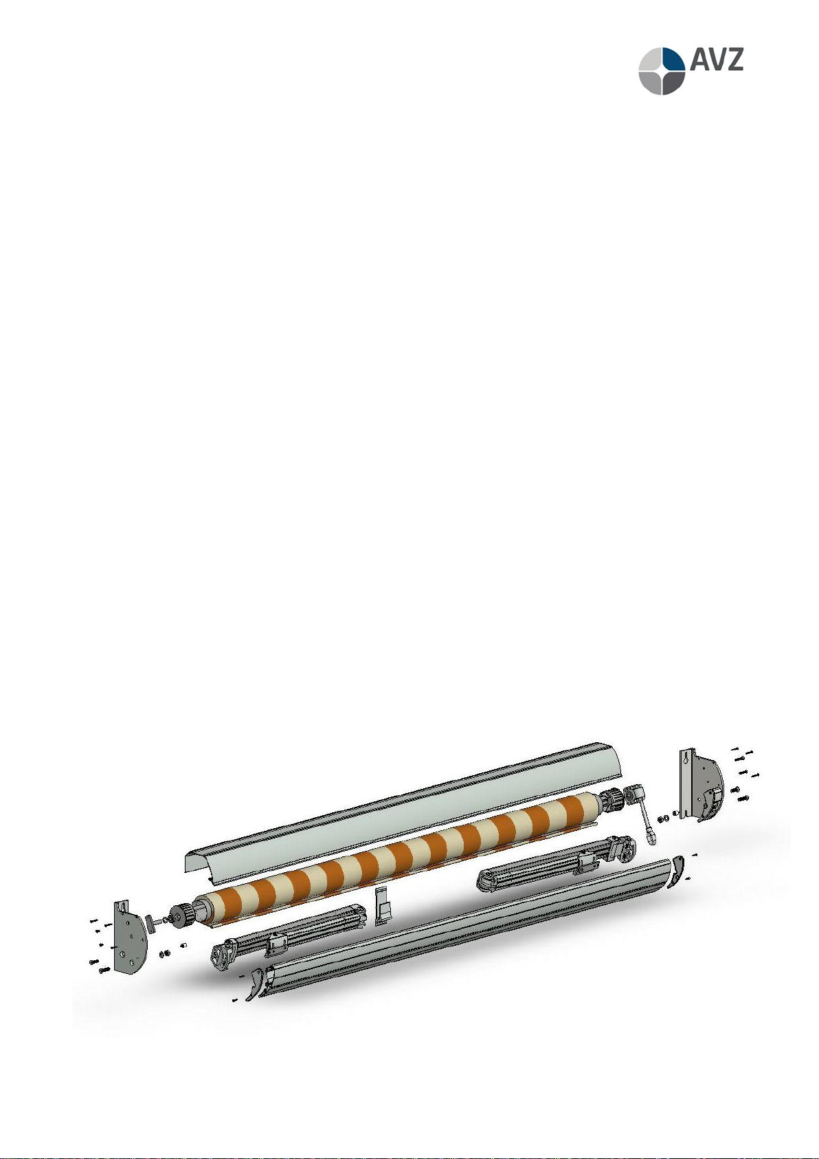
Assembly instructions folding arm awning Picca®
1. Before placing the awning, make sure that the underlying structure is suitable for the
attachment of a folding arm awning (consult a structural engineer, if necessary).
2. Provide sufficient fastening materials for your selected combination of wall and folding
arm awning (request advice from your supplier of fastening materials).
3. Measure out holes for the walls of boards and central bracket. Drill holes in the wall.
NB:Top cover supports M10 bolts and central bracket M6 bolt (if
possible, drill a hole for the central support for better positioning).
4. In case of electric controls: Drill a hole in the wall for the wiring.
5. Place the screw stud with nut or bolts in the plugs/chemical anchors
into the wall so that the wall brackets can be placed with the keyhole
over the nut.
6. Hang the folding awning with the wall brackets against the wall.
7. Fasten the wall support bolts. Ensure that the wall brackets are level
with one another and are vertically level with the wall.
NB: In case of all awnings, an uneven position of the top cover supports will result in an
unequal position of the arms as a result, the awning will not function properly.
8. Fasten the central bracket. When doing so, make sure that the top
cover does not sag.
9. Place a turn rod in case of gear box or connect a motor. Use the
instruction manual of the chosen motor and extend the awning to its
furthest position.
10. Set the desired awning angle between 5° and 35°. Adjust the awning
by slightly loosening the arm holder bolts and subsequently turning
(either in or out) the adjusting bolt between the fabric and arm.
(Tip: Lifting the front profile makes it easier to turn the bolt). Make sure that the front
profile runs parallel to the top cover in the open position. As soon as the desired
position has been realised, fasten the arm holder bolts.
11. Nearly close the awning (leave 30 cm open) and align the front profile so that it follows
the contour of the top cover supports.
12. Close the awning and check that the front profile falls neatly into
place. Is the central bracket positioned properly? Does the front profile
follow the contours of the top cover support? If not, make
adjustments.
13. In case of electric controls, adjust the motor using the accompanying
manual.
Parallel

Picca EN 20-03-2017 page 6
Example diagram folding arm awning Picca® with gear box
(other variants have a similar structure)

Picca EN 20-03-2017 page 7
Example diagram folding arm awning Picca® with gear box
(other variants have a similar structure)
Nbr Qty. Itemnbr. Description Remark
1 2 4210 047-000 Hexagon socket set screw M10x40 (small), stainless DIN 7991
2 2 4210 481-000 Hexagon socket set screw M10x40 (small), stainless DIN 7991
3 2 4000 151-000 Screw countersunk Philips head M6x12, stainless DIN 965
4 6 4210 142-000 Screw countersunk Philips head ST4,2x32, stainless DIN 7982
5 1 4211 200- Top cover support Picca, left
6 1 4210 498-000 Bearing pin
7 1 4210 497-000 Ring 12,1x20x2, synth.
8 1 4460 050-000 Precision bearing with dust seal
9 1 4470 080-000 Bearing bung, synth.
10 1 6253 078-000 Roller 78, steel
11 1 Fabric Fabric
12 1 6293 150- Top cover
13 1 4210 060-001 Alu extruded bracket
14 1 4210 770-001 Folding arms super compact 150 cm, left and right
15 1 4470 088-000 Mono plug 78, synth.
16 1 4210 570-000 Gear box
17 2 4210 053-000 Hexagonal nut M10, stainless DIN 934
18 2 4210 482-000 Washer without chamfer DIN 125-1A, M10, stainless
19 2 4211 209- Runner Picca, complete
20 2 4000 382-000 Screw countersunk Philips head M6x35, stainless DIN 965
21 1 4211 222- Top cover support set Picca gear box, right
22 1 4211 206- Front profile cover Picca, right
23 1 6293 170- Front profile Picca
24 1 4211 204 End cap front profile Picca, left
25 4 4210 140-000 Screw countersunk Philips head ST4,2x22, stainless DIN 7982
Table of contents
Other AVZ Accessories manuals