RoboSense RS-Ruby Lite User manual

RS-Ruby Lite Users’ Manual

RS-Ruby Lite Users’ Manual
I
Revision History
Version Number
Description
Date
Edited by
1.0.0
Initial release
2020-08-03
PD

RS-Ruby Lite Users’ Manual
II
Terminology
MSOP
Main data Stream Output Protocol
DIFOP
Device Information Output Protocol
FOV
Field of View
PTP
Precision Time Protocol
NTP
Network Time Protocol
GPS
Global Positioning System
UTC
Universal Time Coordinated
Wave_mode
Flag of Wave Mode
Temp
Temperature Information
Resv
Reservation
Symbol
Symbol Bit
Ret_id
Identification of Return Wave
Azimuth
Horizontal Angle of LiDAR
Timestamp
Time Point of Encapsulation of a UDP Packet
Header
The Header of a UDP Packet
Tail
The Tail of a UDP Packet
Thermolysis
Loss of Heat from the Object

RS-Ruby Lite Users’ Manual
III
TABLE OF CONTENTS
1 Safety Notice..................................................................................................................................1
2 Introduction.....................................................................................................................................2
3 Product Specifications..................................................................................................................3
4 Interface.......................................................................................................................................... 4
4.1 Power Supply..................................................................................................................... 4
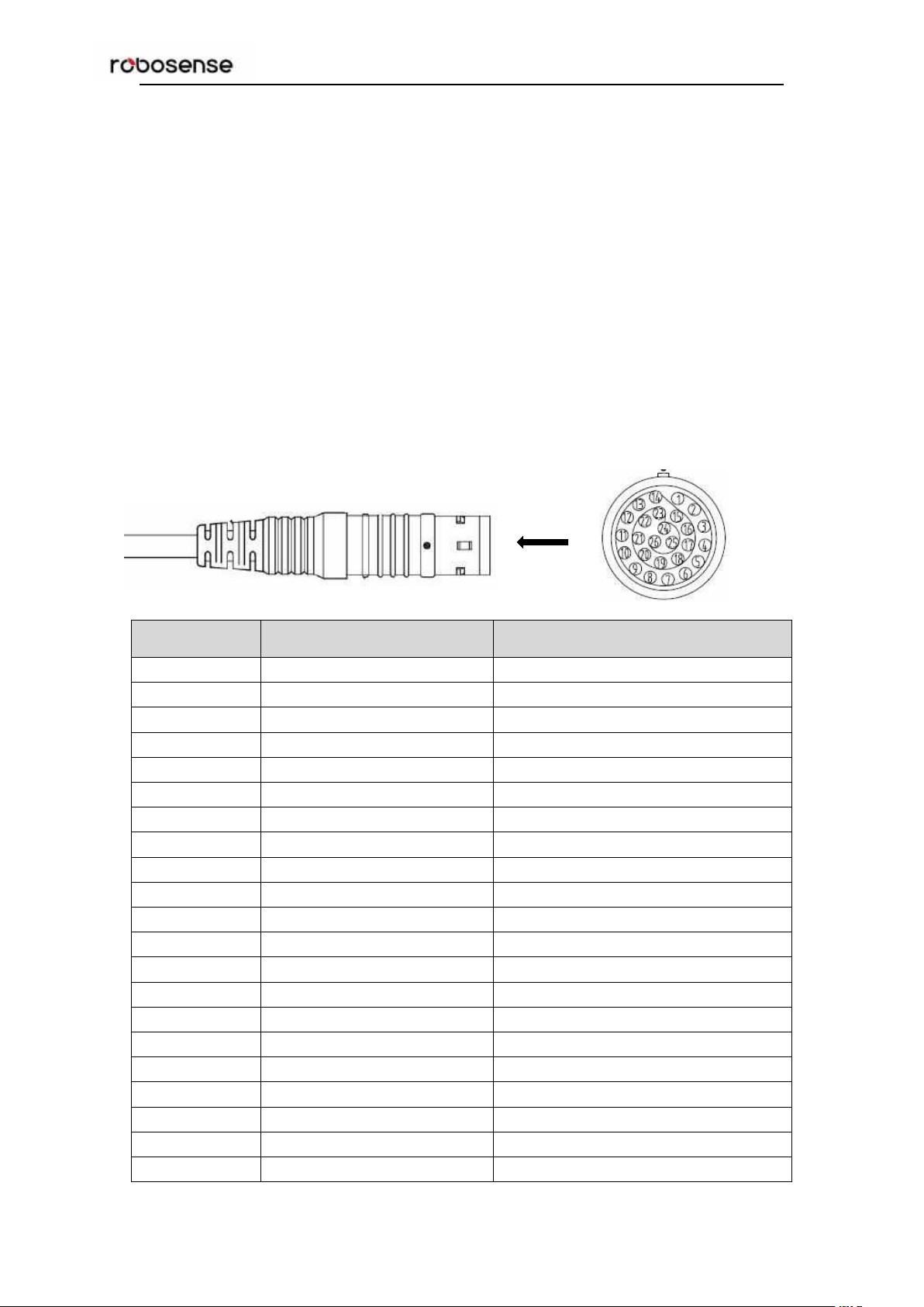
4.2 Data Output Interface of LiDAR...................................................................................... 4
4.3 Interface Box...................................................................................................................... 5
4.4 Interface Box Connection.................................................................................................6
5 Communication Protocol..............................................................................................................7
5.1 MSOP.................................................................................................................................. 8
5.1.1 Header......................................................................................................................9
5.1.2 Data Field................................................................................................................ 9
5.1.3 Tail...........................................................................................................................10
5.1.4 MSOP Data Package.......................................................................................... 10
5.2 DIFOP................................................................................................................................11
6 Time Synchronization.................................................................................................................13
6.1 GPS Synchronization......................................................................................................13
6.1.1 Principle of GPS Synchronization..................................................................... 13
6.1.2 GPS Usage........................................................................................................... 13
6.2 Precision Time Protocol (PTP)...................................................................................... 14
6.2.1 Principle of PTP....................................................................................................14
6.2.2 Topology of PTP................................................................................................... 14
6.2.3 Time Calculation...................................................................................................15
7 Key Specifications...................................................................................................................... 17
7.1 Return Mode.....................................................................................................................17
7.1.1 The Principle of Return Mode............................................................................ 17
7.1.2 Strongest Return.................................................................................................. 17
7.1.3 Strongest, Last and Dual Return Signal.......................................................... 17
7.1.4 Return Mode Flag................................................................................................ 17
7.2 Phase Lock....................................................................................................................... 17
8 Point Cloud...................................................................................................................................19
8.1 Coordinating Mapping.................................................................................................... 19
8.2 Laser Channel in Spatial Distribution...........................................................................20
9 Reflectivity.................................................................................................................................... 23
10 Troubleshooting........................................................................................................................ 24
Appendix A Websever................................................................................................................... 26
A.1 Visiting Websever........................................................................................................... 26
A.2 Parameter Setting........................................................................................................... 27
A.3 Device Diagnose/ Operating Status............................................................................ 28
A.4 Firmware Update.............................................................................................................29
Appendix B The Format of all Register...................................................................................... 30
B.1 Motor Speed (MOT_SPD)............................................................................................. 30

RS-Ruby Lite Users’ Manual
IV
B.2 Ethernet (ETH)................................................................................................................ 30
B.3 FOV Setting (FOV SET)................................................................................................ 31
B.4 Motor Phase Offset (MOT_PHASE)............................................................................ 31
B.5 Top Board Firmware (TOP_FRM)................................................................................ 31
B.6 Bottom Board Firmware (BOT_FRM)..........................................................................31
B.7 Software Version (SOF_FRM)...................................................................................... 31
B.8 Corrected Vertical Angle (COR_VERT_ANG).........................................................32
B.9 Corrected Horizontal Offset Angle (COR_HOR_ANG)..........................................33
B.10 Serial Number (SN)...................................................................................................... 34
B.11 Time (UTC_TIME).........................................................................................................34
B.12 ASCII code in GPSRMC Packet................................................................................ 34
Appendix C RSView...................................................................................................................... 35
C.1 Software Features.......................................................................................................... 35
C.2 Installation of RSView.................................................................................................... 35
C.3 Network Setup.................................................................................................................35
C.4 Visualization of point cloud............................................................................................36
C.5 Save Streaming Sensor Data into PCAP File............................................................37
C.6 Replay Recorded Sensor Data from PCAP Files......................................................38
Appendix D RS-Ruby Lite ROS&ROS2 Package.................................................................... 41
D .1 Software Installation......................................................................................................41
D.2 Download & Compile RS-Ruby Lite ROS Package..................................................41
D.3 Configure PC IP address...............................................................................................42
D.4 Display of the real-time data......................................................................................... 42
D.5 Display offline data......................................................................................................... 43
Appendix E Dimension.................................................................................................................. 44
Appendix F Suggestion of Mechanical LiDAR Mount.............................................................. 45
Appendix G Cleaning of LiDAR................................................................................................... 46
G.1 Attention........................................................................................................................... 46
G.2 Required Materials......................................................................................................... 46
G.3 Cleaning Method.............................................................................................................46

RS-Ruby Lite Users’ Manual
1
Congratulations on your purchase of a RS-Ruby LiDAR Sensor. Please read carefully this
User’s Manual before operating the product. Wish you have a pleasurable product experience
with RS-Ruby.
1 Safety Notice
In order to reduce the risk of electric shock and to avoid violating the warranty, Please do not
privately open the housing and modify the structure of LiDAR.
Laser safety-The laser safety complies with IEC60825-1:2014:
Read Instructions - All safety and operating instructions should be read before operating
the product.
Caution - Warning hot surface.
Follow the Instructions - All operating and use instructions should be followed.
Retain Instructions -The safety and operating instructions should be retained for future
reference.
Heed Warnings - All warnings on the product and in the operating instructions should be
adhered to.
Maintenance - The user should not attempt to maintain the product beyond what is
described in the operating instructions. All other Maintenance should be referred to
RoboSense.

RS-Ruby Lite Users’ Manual
2
2 Introduction
RS-Ruby Lite, the 80-beam LiDAR developed by RoboSense, is the world leading multi-beam
LiDAR that is particularly utilized in perception of environment for autonomous driving.
RS-Ruby Lite is realized by solid-state hybrid LiDAR. The technical details are listed below:
measurement rang: 230 meters
accuracy: ± 5 centimeter
Data rate: up to 1,440,000 points/second (signal return)
Horizontal field of view (FOV): 360°
Vertical field of view (FOV): -25°~15°
80 emitters in RS-Ruby Lite can supply high-frequency laser impulse to scan environment
around LiDAR by rapidly spinning optical module. Advanced digital signal processing and
ranging algorithms calculate point cloud data and reflectivity of objects to enable the machine
to “see” the world and to provide reliable data for localization, navigation and obstacle
perception.
Figure 1: Representation of RS-Ruby Lite Imaging.
The basic operating Instructions of LiDAR:
Connect the device of RS-Ruby Lite with PC;
Parse the data packets to capture the values of azimuth, measure distances and
calibrated reflectivity;
Calculate X, Y, Z coordinates from reported azimuth, measured distance, and vertical
angle;
Store the data of point cloud according to demand;
Check the status of set-up information of device;
Reset the status of network configuration, timing and rotation speed according to
demand.

RS-Ruby Lite Users’ Manual
3
3 Product Specifications1
Table 1: Product Parameters.
Sensor
TOF measuring distance, including the reflectivity
80 channels
Range: from 1.5m to 230m (160m@10%NIST)2
Accuracy: ±5cm (typical value)3
FOV(vertical): -25°~+15°
Angle resolution(vertical): at least 0.1°
FOV (horizontal): 360°
Angle resolution (horizontal/ azimuth): 0.1°(5Hz)/0.2° (10 Hz)/0.4° (20 Hz)
Rotation speed: 300/600/1200 rpm (corresponding to 5/10/20 Hz)
Laser
Class 1
Wavelength: 905nm
Full angle of beam divergence: horizontal 1.5 mrad, vertical 3.6 mrad
Output
Data rate: ~1.44 million points/second
1000M Base Ethernet LAN interface
Communication protocol: UDP
The Information that is included in Data Segment:
Distance
Rotation angle/Azimuth
Calibrated reflectivity
Timestamp (Timer resolution 1 us)
Mechanical/
Electrical/
Operational
Power consumption: 38 W(typical)4
Working voltage: 19-32 VDC (19V is recommended)
Weight: 3.75kg
Dimensions: Diameter 166mm × Height 148.5mm
Ingress Protection Rating: IP67
Operation temperature: -30℃~+60℃5
Storage temperature: -40℃~+85℃
1The following data is only for mass-produced products. Any samples, testing machines and other
non-mass-produced versions may not be referred to this specification. If you have any questions, please
contact RoboSense sales.
2The measurement target of rang is a 10% NIST Diffuse Reflectance Calibration Targets, the test
performance is depending on circumstance factors, not only temperature, range and reflectivity but also
including other uncontrollable factors.
3The measurement target of accuracy is a 50% NIST Diffuse Reflectance Calibration Targets, the test
performance is depending on circumstance factors, not only temperature, range and reflectivity but also
including other uncontrollable factors.
4The test performance of power consumption is depending on circumstance factors, not only
temperature, range and reflectivity but also including other uncontrollable factors.
5The operating temperature is depending on circumstance factors, not only light condition, air flow but
also including other uncontrollable factors.

RS-Ruby Lite Users’ Manual
4
4 Interface
4.1 Power Supply
The supply voltage should remain in the range of 19~32 VDC with utilization of Interface-Box.
The recommend supply voltage is 19 VDC. The power consumption is about 38 W.
4.2 Data Output Interface of LiDAR
The data output access of RS-Ruby Lite is physically protected by an aviation terminal
connector. From the LiDAR to the aviation connector the cable length is 1 meter. The pins of
the aviation terminal connector are defined as follow:
Pin
Wire Color
Function
1
Black/Brown
GROUND
2
Black
Gigabit network differential signal
3
Brown
Gigabit network differential signal
4
Black/Green
GROUND
5
Red
Gigabit network differential signal
6
Orange
Gigabit network differential signal
7
White/Orange
GROUND
8
Yellow
Gigabit network differential signal
9
Green
Gigabit network differential signal
10
White/Purple
GROUND
11
Blue
Gigabit network differential signal
12
Purple
Gigabit network differential signal
13
Yellow/Brown
GROUND
14
Black/Red
GROUND
15
Black/Orange
PWR
16
Black/Yellow
PWR
17
White/Black
PWR
18
White/Brown
PWR
19
White/Red
PWR
20
White/Yellow
PWR
21
White/Green
Reserved serial signal

RS-Ruby Lite Users’ Manual
5
22
White/Blue
Reserved serial signal
23
Yellow/Green
GPS_PULSE
24
Yellow/Gray
GPS_REC
25
Yellow/Blue
Reserved signal
26
Yellow/Purple
GROUND
Figure 2: Aviation Connector Pin Number of RS-Ruby Lite.
4.3 Interface Box
In order to connect the RS-Ruby Lite conveniently, there is an interface box provided.
There are accesses for power supply, Ethernet and GPS on the Interface Box. Meanwhile,
there are also indicator LEDs for checking the status of power supply.
For those accesses, a SH1.0-6P female connector is the interface for GPS signal input.
Another interface is a DC 5.5~2.1 female connector for power input. The last one is a Rj45
Ethernet connector for RS-Ruby Lite data transport. The cable on Interface-Box with Aviation
connector is 3m. If you have other requests for cable length, please contact technical support
of RoboSense. The definition of GPS PIN map and corresponding voltage level are shown as
follow:
Pin No.
Function
1
GPS_PULSE
2
+5V
3
GND
4
GPS_REC
5
GND
6
NC
Figure 3: Interface Definition of Interface Box.
Notice: When RS-Ruby Lite connects its grounding system with an external system, the
external power supply system should share the same grounding system with that of the GPS.
When the power input is in order, the red LED which indicates the power input status will be

RS-Ruby Lite Users’ Manual
6
lighted. The green LED lights always by default. While red LED is dark, Interface Box is in
protection status. While red or green LED (GPS Module connected) is dark, please check
whether the power supply is out of order or damaged. If it is not intact, that could prove that the
Interface Box is damaged. Please send the damaged Interface Box back to RoboSense
Service.
GPS interface definition: GPS REC stands for GPS input, GPS PULSE stands for GPS PPS
input.
Interface of power supply is standard DC 5.5-2.1 connector.
4.4 Interface Box Connection
Figure 4: Diagram of Interface Box Connection.

RS-Ruby Lite Users’ Manual
7
5 Communication Protocol
RS-Ruby Lite adopts IP/UDP protocol and communicates with computer through gigabit
Ethernet. In this User Guide the length of UDP packet is set up to 1248 byte. The IP address
and port number of RS-Ruby Lite is set in the factory as shown in the Table 2, but can be
changed by user as needed.
Table 2: The IP Address and Port Number Set in the Factory.
IP Address
MSOP Port No.
DIFOP Port No.
RS-Ruby Lite
192.168.1.200
6699
7788
PC
192.168.1.102
The default MAC Address of each RS-Ruby Lite is already set up in the factory with
uniqueness. In order to establishing the communication between a RS-Ruby Lite and a
computer, the IP Address of the computer should be set at the same network segment. For
instance, IP Address is 192.168.1.X (X can be taken by a value from 1~254), subnet mask:
255.255.255.0. If the internet setting of the sensor is unknown, please set the subnet mask as
0.0.0.0, connect the sensor to the computer, and capture UDP packet to get the information of
IP and Port through Wireshark.
The output message from RS-Ruby Lite is called MSOP. The Information of MSOP is shown
as follow:
Table 3: Overview of the MSOP.
Protocol
Abbreviation
Function
Type
Size
Main data Stream Output Protocol
MSOP
Scan Data Output
UDP
1248 byte
Device Information Output Protocol
DIFOP
Device Info Output
UDP
1248 byte
Note: In the following chapters only the valid payload (1248 byte) will be discussed.

RS-Ruby Lite Users’ Manual
8
5.1 MSOP
I/O type: Device outputs data and computer parses data.
Default port number is 6699.
MSOP packet outputs data information of the 3D environment. Each MSOP packet from
sensor is 1248-byte in length and consists of reported distance, calibrated reflectivity values,
azimuth values and a timestamp in UDP header.
Each MSOP packet payload is 1248-byte in length and consists of an 80-byte header and a
976-byte data field containing 4 blocks of 244-byte data records and a last 192-byte tail.
The basic data structure of a MSOP packet for single return is as shown in Figure 5:
MSOP Packet (1248 bytes)
192bytes
80 bytes
data packet
4*244bytes = 976bytes
80 bytes
(11th
~20th
Byte is
time
stamp)
Header
192 bytes
Tail
Figure 5: MSOP Packet of RS-Ruby Lite in Single Return Mode.
Azimuth 1
data 1
channel data 2
0xFE
Data block 0
Ret_id
channel data 1
channel data ...
channel data 80
Azimuth 2
data 1
channel data 2
0xFE
Data block 1
Ret_id
channel data 1
channel data ...
channel data 80
Azimuth 3
data 1
channel data 2
0xFE
Data block 2
Ret_id
channel data 1
channel data ...
channel data 80
Azimuth 4
data 1
channel data 2
0xFE
Data block 3
Ret_id
channel data 1
channel data ...
channel data 80

RS-Ruby Lite Users’ Manual
9
5.1.1 Header
The 80-byte Header is used to mark the start position of data, return mode setting, sensor
temperature and timestamp. The detail of the header is as shown in Table 4.
Table 4: Format of Header.
Header (80bytes)
Header
Resv
Wave_mode
Temp
Time
Resv
4bytes
3bytes
1byte
2bytes
10bytes
60bytes
Header: this can be used for packets identification: 0x55, 0xAA, 0x05, 0x5A (Default Value)
Wave_mode: Big-Endian mode, lower 4 bits are used to represent the return mode of the
LiDAR, for instance:00000001 stands for that first return mode is chosen.
Temp: the temperature of device;
Time: it is used to save the timestamp. In the defined timestamp the system time is recorded,
resolution is 1us, the definition of time can be found in the appendix B.11.
Resv: those bytes are reserved.
5.1.2 Data Field
The value of measurement result is saved in the data field, in total 976 byte. It consists of 4
data blocks, the length of each data block is 244 bytes. Each block stands for a complete
round of distance measuring for all 80 channels. The definition is shown as follow:
Table 5: Data Block Definition.
Data block n (244bytes)
Symbol
Ret_id
Azimuth
Channel1_data
...
Channel80_data
1byte
1byte
2bytes
3bytes
...
3bytes
Symbol: identification bit, default value: 0xFE;
Ret_id: it is used to represent which echo measurement is for this block;
Azimuth: the information of horizontal rotation angle. This angle information will be used to
calculate the 3D coordinate with all following 80-channel data in the same block. In following
section, it will be completely explained.
Channel data: the length of each channel data is 3 bytes, each block includes 80-channel
data (further details could be seen in Table 6). (The relationship between the number of
channel and vertical angle can be found in chapter 8.)
5.1.2.1 Calculation of the Azimuth
In each data block the value of azimuth is measured once and this azimuth corresponds to the
first position of the first laser emission (the first channel data in this block). The rotation angle is
recorded by angle encoder. The zero position of angle encoder is the zero degree of azimuth.
The resolution of angle is 0.01°.
For instance, in Figure 6, the azimuth value is calculated as follow:
Get azimuth values (HEX): 0x59, 0x39
Combine to a 16-bit, unsigned integer (HEX): 0x 5939
Convert the value to decimal (DEC): 22841
Divided by 100 (DEC): 228.41°

RS-Ruby Lite Users’ Manual
10
Hence, the angle value in this block is 228.41°.
Notice: the 0°axis of azimuth is co-axis and same positive direction with the Y axis in Figure
12.
5.1.2.2 Channel Data
Channel data is 3 bytes. The higher 2 bytes of them are used to save the distance information.
The lower one byte stands for reflectivity.
Table 6: The Format of Channel Data.
Channel data n (3 byte)
Distance (2 bytes)
Reflectivity (1 byte)
Distance1[15:8]
Distance2[7:0]
Reflectivity [7:0]
Distance is 2 bytes, resolution: 0.5 cm.
For instance, in Figure 6, the explanation of Channel data is as follow:
Get the higher 2 bytes(HEX): 0x08 (Distance 1), 0x4b (Distance 2).
Combine to a 16-bit unsigned integer (HEX):0x084b
Convert the value to decimal (DEC):2123
According to the resolution 0.5 cm, change to meter: 2123 * 0.005 = 10.615 m
Hence, the distance between sensor and measurement object is 10.615 m.
Reflectivity is a relative value, please find the concrete definition in “chapter 9 Reflectivity”,
Reflectivity could show energy of the light return from measuring object in the real
circumstance. Through analytic of reflectivity, the object of different materials can be
distinguished.
5.1.3 Tail
The 4-byte Tail is reserved as the checksum.
5.1.4 MSOP Data Package
The following figure shows the format of MSOP data packet and relevant parsing processes in
next page.

RS-Ruby Lite Users’ Manual
11
Figure 6: MSOP Packet of RS-Ruby Lite in Single Return Mode.
5.2 DIFOP
Device Info Output Protocol, abbreviation: DIFOP
I/O Type: output from device, input to PC
Default port number: 7788
DIFOP is a protocol that reports and outputs device information including the device serial
number (S/N), firmware version, internet setting, calibration data, electrical machine setting
and operation status, fault detection information. The UDP packet of DIFOP is sent to PC
from LiDAR in a confirm time interval. It is a viewer for users to get comprehensive details
about the device.
Each DIFOP packet is 1248 byte long, and comprises an 8-byte Header, a 1238-byte data
field, and a 2-byte Tail.
Table 7: Data Format of DIFOP Packet.
No.
Information
Offset
Length(byte)
Header
0
DIFOP header
0
8
Data
1
Motor rotation speed
8
2
2
Source IP Address (LiDAR IP)
10
4
Destination IP Address
14
4
LiDAR MAC Address
18
6
Data block 0
Channel 1 data calculation
distance byte: 0x08, 0x4b; Atten byte :0x08
combine the byte: 0x084b; get atten :0x08
get distance: 0x084b; combine the byte :0x08
convert to decimal :2123; convert to decimal :8
multiply by :0.5cm; result :8
result :10.615m;
Header:0x55,0xaa,0x05,0x5a
Data block 1
Azimuth 2 calculation
second azimuth :0x5939
get azimuth :0x59 & 0x39
combine the byte :0x5939
convert to decimal :22841
divide by :100
result :228.41°

RS-Ruby Lite Users’ Manual
12
Note:The Header (the DIFOP identifier) in the table above is 0xA5, 0xFF, 0x00, 0x5A, 0x11, 0x11,
0x55, 0x55. This sequence can be used to identify the packet.
The tail is 0x0F,0xF0.
For definition of information registers as well as their usage, please check more details in
Appendix B of this manual.
Port Number of MSOP
24
2
Reserved
26
2
Port Number of DIFOP
28
2
Reserved
30
2
3
FOV of start angle
32
2
FOV of end angle
34
2
4
Reserved
36
2
5
Motor Phase Lock
38
2
6
Top Board Firmware Version
40
5
Bottom Board Firmware Version
45
5
Bottom Board Software Version
50
5
Electrical Motor Firmware Version
55
5
LiDAR Hardware Version
60
3
7
Reserved
63
229
8
S/N
292
6
9
Correction Value of Zero Angle
298
2
10
Return mode
300
1
11
Time Synchronization Mode
301
1
Time Synchronization Status
302
1
UTC time
303
10
12
Operation Status
313
24
13
Reserved
337
5
14
Reserve for Fault Diagnose
342
9
Number of Start
351
2
SER (symbol error rate) of Magnetic Ring
353
4
GPS Status
357
1
Temperature Detection
358
10
Reserved
368
3
Real-time Phase
371
2
Real-time Rotation Speed
373
2
Reserved
375
7
15
GPRMC
382
86
16
Horizontal Angle Correction
468
384
Vertical Angle Correction
852
384
17
Reserved
1236
10
Tail
18
Tail
1246
2

RS-Ruby Lite Users’ Manual
13
6 Time Synchronization
RS-Ruby Lite supports two time synchronization modes, one is external GPS + PPS and the
other is PTP. Mode switching can be realized through using web application(please refer to
Appendix A.2).
6.1 GPS Synchronization
The time of RS-Ruby Lite can be synchronized with GPS module from external.
6.1.1 Principle of GPS Synchronization
Figure 7: Timing Sequence Diagram of GPS Synchronization.
The GPS module keeps generating synchronization Pulse Per Second (PPS) signal, GPRMC
messages and sends them to the sensor. The pulse width of the PPS should be between 10us
to 200ms, and the GPRMC message should be received within 500ms after this rising edge of
this PPS signal.
6.1.2 GPS Usage
GPS_REC receives the signal from GPS module with standard serial RS232 communication
protocol. The interface format of GPS_REC is SH1.0-6 female connector, the pin definition can
be referred in Figure 3.
GPS PULSE receives the positive PPS signal from the GPS module and requests voltage
between 3.0 V ~ 15.0 V.
PIN +5V of GPS interface can supply power to GPS module. (If GPS module is only allowed to
use +3.3V as power supply, please do not use this +5V PIN on Interface Box. Please
exchange the +5V to +3.3V)
PIN GND is connected to ground wire of the GPS module.
The GPS module should be set to 9600bps baud rate, 8-bit data bit, no parity and 1 stop bit.
RS-LiDAR-Ruby only reads the GPRMC message from GPS module., the GPSMRC message
format is shown as below:
Reset part of sub-second
According to GPRMC message, synchronize the part of second

RS-Ruby Lite Users’ Manual
14
$GPRMC, <1>,<2>,<3>,<4>,<5>,<6>,<7>,<8>,<9>,<10>,<11>,<12>*hh
<1>UTC time
<2>validity-A-ok, V-invalid
<3>Latitude
<4>North/South
<5>Longitude
<6>East/West
<7>Ground speed
<8>True course
<9>UTC date
<10>Variation
<11>East/West
<12>Mode(A/D/E/N=)
*hh checksum from $ to*
Notice:
1. The interval of 1PPS pulse must be controlled within 1s ±100μs;
2. In GPRMC message, the status bit (<12>Mode>) must be A, otherwise, synchronization
timing cannot be given;
3. The different GPS module could send out different GPRMC message length, the RS-Ruby
Lite could be compatible with the most GPS modules on the market. Please contact
RoboSense of technical support when it is incompatible.
6.2 Precision Time Protocol (PTP)
6.2.1 Principle of PTP
PTP (Precision Time Protocol) defines a protocol enabling precise synchronization of clocks in
measurement and control systems, also used in different devices. Compared with other
synchronization mechanisms, PTP has many advantages:
1) In comparison with NTP (Network Time Protocol), PTP could meet much higher demand of
time synchronization. NTP could only satisfy the sub-second-level synchronization. However,
the synchronization accuracy of PTP is sub-microsecond.
2) In comparison with GPS (Global Positioning System), the cost of purchase and
maintenance of PTP is much lower.
6.2.2 Topology of PTP
The setup steps of PTP:
1)In web application, the PTP Mode should be chosen (referring to A.2 Web configuration);
2)Prepare a PTP Master ;
3)Ethernet Switch;
4)The device supporting PTP.
5)The Topology is shown as below:

RS-Ruby Lite Users’ Manual
15
Figure 8: Topology of LiDAR, PC and PTP Master.
Notice:
1. PTP Master is a third-party device that is not included in accessories while shipment. It
needs to be bought by user.
2. Our product is only as a PTP Slave that gets the synchronized time from PTP Master. The
synchronization accuracy cannot be examined by LiDAR. If there is deviation between LiDAR
time and real time, please check the accuracy of Master Clock.
3. If the connectivity is interrupted after synchronization, the LiDAR time will continue counting
based on the clock inside of LiDAR. The LiDAR time will be reset until the LiDAR is powered
up again.
6.2.3 Time Calculation
In MSOP packet, it includes time stamp information. When the external synchronization is not
active, the internal timing will start from a default origin.
Figure 9: the Data Format of PTP.
(1) The time stamps are divided into second part and nanosecond part. The second part
shown in Figure 9 is 0x00003e1942c2(1041842882); the nanosecond part is
header
sec
ns
Table of contents
Other RoboSense Accessories manuals
Popular Accessories manuals by other brands

LEGRAND
LEGRAND Wattstopper UT-355 installation instructions

Kramer
Kramer TBUS-204 quick start guide

Johnson Controls
Johnson Controls WRZ Series installation instructions

Tendercare
Tendercare Snappi Sun Hood and Transparent Rain Shield instructions

Campbell
Campbell 4-Channel Current/Voltage SDM-CVO4 user guide

Sharp
Sharp User Authentication Operation manual