AW BREATH-CLEAN PAPR Guide

1
B
BR
RE
EA
AT
TH
H-
-C
CL
LE
EA
AN
N
P
PA
AP
PR
R
POWERED AIR PURIFYING RESPIRATOR HELMET
INSTALLATION, OPERATIONS AND REPLACEMENT PARTS MANUAL

2
TABLE OF CONTENTS
WARRANTY .................................................................................................................................................................3
CE –EU DECLARATION OF CONFORMITY ..........................................................................................................................3
SAFETY PRECAUTIONS ....................................................................................................................................................4
INTRODUCTION.............................................................................................................................................................7
UNPACK AND ASSEMBLY ................................................................................................................................................8
FILTER REPLACEMENT.....................................................................................................................................................8
INSTALLING THE BATTERY/CHARGING ...............................................................................................................................9
INSTALLING THE POWER UNIT TO THE BELT.....................................................................................................................10
CONNECTING THE AIR TUBE..........................................................................................................................................10
AIRFLOW TESTING.......................................................................................................................................................11
AIRFLOW ALARM TEST.................................................................................................................................................11
FITTING AND ADJUSTMENT ...........................................................................................................................................11
OPERATION –PAPR POWERED AIR RESPIRATOR ..............................................................................................................12
OPERATION –ADF AUTO DARKENING LENS ....................................................................................................................12
MAINTENANCE AND STORAGE -PAPR............................................................................................................................15
MAINTENANCE AND STORAGE –ADF AUTO DARKENING LENS ............................................................................................15
PAPR WARNING SOUNDS............................................................................................................................................16
SPECIFICATIONS –PAPR SYSTEM...................................................................................................................................16
SPECIFICATION S-ADF AUTO DARKENING LENS................................................................................................................17
TROUBLESHOOTING.....................................................................................................................................................18
PARTS BREAKDOWN ....................................................................................................................................................19
INTRODUCTION
Thank you for purchasing an American Weldquip product. The American Weldquip product you have purchased has been carefully
manufactured, assembled, and fully tested. This manual contains information on the installation, operation, maintenance, and replacement
part breakdown. Please read, understand, and follow all safety instructions, warnings and procedures. Keep this manual handy for
referencing installation, operation, maintenance, and part ordering information. While every precaution has been taken as to the accuracy in
this manual, American Weldquip, Inc. assumes no responsibility for errors or omissions. American Weldquip, Inc. assumes no liability for
damages resulting from the use of the information contained in this manual. American Weldquip, Inc. shall have no liability to the buyer for
consequential damages or expenses by any defect whatsoever.

3
WARRANTY
AMERICAN WELDQUIP MIG guns and parts are warranted to be free of defects in material and/or workmanship for the period of time listed
below. For any product found to be defective under normal use, AMERICAN WELDQUIP, INC. at our option, will repair, replace or issue a
credit for the value of the defective product. All warranty claims must be submitted by the original purchaser. Use of non-genuine AMERICAN
WELDQUIP parts and/or consumables may damage and/or severely limit the performance of the equipment which may limit or void any
warranties. AMERICAN WELDQUIP, INC. will not assume responsibility for incidental damages or expenses related to any defect. This
warranty does not cover damage caused by misuse or abuse, accident, alteration of product, improper installation, misapplication, lack of
reasonable care and maintenance, unauthorized repairs or modifications, loss of use while at a repair facility or other conditions that are
beyond the control of American Weldquip, Inc.
A Return Authorization Number (RA#) must be attained from the factory for any product being returned for Warranty Repair or Replacement.
All returned product must be shipped freight prepaid by the sender. No- charge replacements, repaired products, or credit will be issued,
once the returned product has been evaluated and warranty condition has been verified. If an immediate replacement is required before
proper warranty evaluation, a purchase order number is required and the goods will be invoiced. A credit will be issued once it is determined
that a warranty condition exists.
STANDARD WARRANTY
All Semi-Automatic, Automatic, Robotic MIG TORCHES and Components = 120 Days
MIG Torch Trigger Switches (Contacts only) -Excludes Smoke Extraction = LIFETIME
Robotic Nozzle Cleaning Stations, Wire Cutter = 90 Days
Robotic Peripherals, ArcSafe, Gun Mounts = 90 Days
TIG POINT Tungsten Electrode Grinders = 90 Days
LIMITED EXTENDED WARRANTY PROTECTION
This limited extended warranty protection expands coverage to loyal customers who use all GENUINE American Weldquip
consumables. Customers filing a claim under the extended warranty will need to prove, by providing past invoices, that they have been
purchasing and using Genuine American Weldquip consumables.
All Semi-Automatic, Automatic, Robotic MIG TORCHES and Components = 1 YEAR
MIG Torch Trigger Switches (Contacts only) -Excludes Smoke Extraction = LIFETIME
MIG Torch Handles = LIFETIME
Robotic Nozzle Cleaning Stations, Wire Cutter = 90 Days
Robotic Peripherals, ArcSafe, Gun Mounts = 90 Days
TIG POINT Tungsten Electrode Grinders = 90 Days
CE –EU DECLARATION OF CONFORMITY
This product has met the requirements set by the EU directive and the products listed below are in conformity with the provisions of:
Breath Right PAPR Powered Air Purifying Helmet - The system complies with the requirements of European Standard EN 12941:
1998+A2:2008 class TH2 P R S L . The Respiratory System is designed to provide a supply of filtered air via a breathing tube to a
welding headpiece. The equipment can be used in environment that requires a class TH2P breathing protection device. It protects
against articulate contamination.
All components used in Respiratory System must be manufacturer approved parts, and must be used in accordance with the
instructions in this manual.
For EU Declaration of Conformity letter for this product please visit our website –www.weldquip.com or email us at

4
SAFETY PRECAUTIONS –READ BEFORE USING
Before installing, operating or performing maintenance please read the safety precautions below. Failure to observe safety precautions
can result in injury or death.
CALIFORNIA PROPOSITION 65 WARNINGS
This product, when used for welding and cutting, can produce fumes or gases which contain chemicals known to cause birth defects and
cancer. (California Health & Safety Code Section 25249.5 et seq.)
EMF –ELECTRICAL AND MAGNETIC FIELDS MAY BE DANGEROUS
Electrical current flowing through any conductor causes localized Electric and Magnetic Fields (EMF). Welding current creates and EMF field
around welding cables and welding machines.
WARNING - EMF fields may interfere with some pacemakers and other medical implants. Implanted medical device wearers should
consult their doctor before operating or going near any arc welding applications. In addition, exposure to EMF fields in welding may have
other unknown health effects.
Welders should use the below procedures to minimize the exposure to EMF fields from the welding circuit.
1) Route the cables close together. Secure by twisting, taping or using a cable cover to keep together.
2) Never coil, wrap or drape welding cables around your body.
3) Do not place your body between welding cables. Arrange so that cables are on one side and away from the operator.
4) Connect the work clamp(ground) to the workpiece as close as possible to the area to be welded.
5) Do not sit, lean and stand next to the welding power source.
FUMES AND GASES CAN BE DANGEROUS
WARNING - WELDING AND CUTTING PRODUCE FUMES AND GASES THAT ARE HAZARDOUS TO YOUR HEALTH
1) Do not breathe the fumes and gases as they can cause asphyxiation.
2) Fumes and gases generated from welding can cause severe injury to respiratory system and even death. In poorly vented areas it is
required to properly ventilate the area and/or use local forced ventilation or other fume control equipment at the arc to remove
welding and cutting fumes and gases.
3) The recommended way to determine adequate ventilation is to sample for the composition and quantity of fumes and gases to
which personnel are exposed. The worker exposer level should be checked initially and periodically thereafter to maintain
applicable OSHA PEL and ACGIH TVL limits.
4) In a poorly ventilated area, it is necessary to wear an approved air-supplied respirator.
5) Always read and understand the Safety Data Sheets (SDSs) and the manufacturer’s instructions for adhesives, coatings, cleaners,
consumables, coolants, degreasers, fluxes and metals.
6) Always have a trained watch-person nearby. Welding and cutting fumes and gases can displace air and lower the oxygen level
causing injury or death. Be sure the breathing air is safe.
7) Do not weld or cut in locations near degreasing, cleaning, or spraying operations. The heat and rays of the arc can react with vapors
to form highly toxic and irritating gases.
8) Do not weld or cut on coated metals, such as galvanized, lead, or cadmium plated steel, unless the coating is removed from the
weld area, the area is well ventilated, and while wearing an air-supplied respirator. The coatings and any metals containing these
elements can give off toxic fumes if welded.

5
ELECTRIC SHOCK CAN KILL
WARNING - ELECTRICAL SHOCK CAN KILL. DO NOT TOUCH LIVE ELECTRICAL PARTS AND/OR USE IN DAMP
LOCATIONS.
1) The electrode and work (ground) circuit is electrically “HOT” whenever the welding equipment is on. Do not
touch these electrically live parts with your bare skin or wet/damp clothing. Wear dry, hole-free gloves. Incorrectly installed or
improperly grounded equipment is a hazard.
2) Insulate yourself from work and ground using dry insulating mats or covers big enough to prevent any physical contact with the
work or ground.
3) Additional safety precautions are required when any of the following electrically hazardous conditions are present: in damp
locations or while wearing wet clothing; on metal structures such as floors, gratings or scaffolds; when in cramped positions such as
sitting, kneeling or lying; or when there is a high risk of unavoidable or accidental contact with the workpiece or ground. For these
conditions, use the following equipment in order presented: 1) a semi-automatic DC constant voltage, 2) a DC manual (stick) welder
or 3) an AC welder with reduced open-circuit voltage. In most situations, use of a DC, constant voltage wire welder is recommended
and do not work alone!
4) Disconnect input power or stop engine before installing or servicing this equipment. Lockout/tag out input power according to
OSHA 29 CFR 1910.147 (see Safety Standards).
5) Properly install ground and operate this equipment according to its Owner’s Manual and national, state/provincial and local codes.
6) Always verify the supply ground. Make sure that input power cord ground wire is properly connected to ground terminal in
disconnect box or that cord plug is connected to a properly grounded receptacle outlet.
7) Keep cords dry, free of oil and grease and protected from hot metal and sparks.
8) Frequently inspect input power cord for damage or bare wiring. Replace cord immediately if damaged. Bare wiring can kill.
9) Turn off all equipment when not in use.
10) Do not use worn, damaged, undersized or poorly spliced cables. It is illegal to use electrical tape to repair torch power cable or
ground cable that has damaged outer insulation. The cable must be replaced.
11) Do not drape cables over your body.
12) Do not touch electrode if you are in contact with the work, ground or another electrode from a different machine.
13) Do not touch electrode holders connected to two welding machines at the same time since double open circuit voltage will be
present.
14) Use only well-maintained equipment. Repair or replace damaged parts at once. Maintain unit according to manual.
15) Wear a safety harness if working above floor level.
16) Keep all panels and covers securely in place.
17) Clamp work cable with good metal-to-metal contact to workpiece or worktable as near the weld as practical.
18) Do not connect more than one electrode or work cable to any single weld output terminal. Disconnect cable for process when not
in use.
ARC RAYS HAZARDS
WARNING –A WELDING ARC EMITS ULTRAVIOLET (UV) AND OTHER RADIATION AND CAN CAUSE
SERIOUS INJURY TO UNPROTECTED SKIN AND EYES.
1) Use a shield with the proper filter and cover plates to protect your eyes from sparks and the
rays of the arc when welding or observing open arc welding. Headshield and filter lens should
conform to ANSI Z87. I standards.
2) Use suitable clothing made from durable flame-resistant material to protect your skin and that
of your helpers from the arc rays.
3) Protect other nearby personnel with suitable, non-flammable screening and/or warn them not
to watch the arc nor expose themselves to the arc rays or to hot spatter or metal.

6
WELDING AND CUTTING CAN CAUSE FIRE OR EXPLOSION
WARNING –Welding and cutting produces sparks that fly off from the arc and can cause fires and/or
explosions.
1) Welding or cutting on closed containers, such as tanks, drums or pipes can cause them to blow up. Sparks can fly off from the
welding or cutting arc. The flying sparks, hot work piece and hot equipment can cause fires and burns.
2) Accidental contact of electrode to metal objects can cause sparks, explosion, overheating or fire. Check and be sure the area is safe
before doing any welding or cutting.
3) Do not weld or cut where flying sparks can strike flammable material.
4) Remove all flammables and fire hazards from the welding area. If this is not possible, tightly cover them with approved covers to
prevent the welding sparks from starting a fire.
5) When not welding, make certain no part of the electrode circuit is touching the work or ground. Accidental contact can cause
overheating and create a fire hazard.
6) Be alert that welding sparks and hot materials from welding and cutting can easily go through small cracks and openings and cause
a fire in the adjacent areas.
7) Follow requirements in OSHA 1910.252 (a) (2) (iv) and NFPA 51B for hot work and have a fire watcher and extinguisher nearby.
8) Do not heat, cut or weld tanks, drums or containers that have held combustibles until the proper steps have been taken to ensure
that such procedures will not cause flammable or toxic vapors from substances inside. They can cause an explosion even though
they have been “cleaned”. For information, purchase “Recommended Safe Practices for the Preparation for Welding and Cutting of
Containers and Piping That Have Held Hazardous Substances”, AWS F4.1 from the American Welding Society.
9) Do not weld or cut where the atmosphere may contain flammable dust, gas, or liquid vapors (such as gasoline).
10) Sparks and spatter are thrown from the welding arc. Wear oil free protective garments such as leather gloves, heavy shirt, cuff less
trousers, high shoes and a cap over your hair. Wear ear plugs when welding out of position or in confined places. Always wear
safety glasses with side shields when in a welding area.
11) Connect work cable to the work as close to the welding or cutting area as practical to prevent welding or cutting current from
traveling long, possibly unknown paths and causing electric shock, sparks and fire hazards.
12) Do not use welder to thaw frozen pipes.
13) Remove any combustibles, such as a butane lighter or matches, from your person before doing any welding or cutting.
14) Inspect area to ensure it is free of sparks, glowing embers, and flames after work is complete.
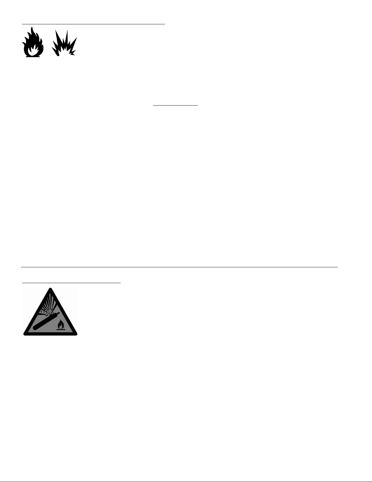
CYLINDERS CAN EXPLODE IF DAMAGED
WARNING –Compressed gas cylinders contain gas under high pressure and/or flammable gas. If damaged,
the cylinder can explode.
1) Use only compressed gas cylinders containing the correct shielding gas for the process used and properly operating regulators
designed for the gas and pressure used. All hoses, fittings, etc. should be suitable for the application and maintained in good
condition.
2) Always keep cylinders in an upright position securely chained to an undercarriage or fixed support.
3) Cylinders should be located away from areas where they may be struck or subjected to physical damage and a safe distance from
arc welding or cutting operations and any other source of heat, sparks, or flame.
4) Never allow the electrode, electrode holder or any other electrically “hot” parts to touch a cylinder.
5) Keep your head and face away from the cylinder valve outlet when opening the cylinder valve.
6) Valve protection caps should always be in place and hand tight except when the cylinder is in use or connected for use.
7) Read and follow the instructions on compressed gas cylinders, associated equipment, and CGA publication P-l, “Precautions for Safe
Handling of Compressed Gases in Cylinders,” available from the Compressed Gas Association, 14501 George Carter Way Chantilly,
VA 20151.

7
INTRODUCTION
PAPR Respiratory System is a combined face and breathing protection device for increased safety and comfort during welding.
Please read these instructions carefully before unpacking. For proper use, see User Instructions or contact manufacturers for
help.
WARNING AND LIMITATIONS FOR USE
Before each use, inspect the Respiratory System for damage and verify it operates properly. Before using the Respiratory System,
test air flow to verify it is providing an adequate volume of air.
Always wear the Respiratory System and do not remove the head top or turn off the air filter unit until outside the contaminated
area, otherwise, there is a risk of high concentration of CO2 and oxygen level in the head top will fall, thus little or no protection is
given.
If you are not sure about the concentration of pollution, or about equipment performance, ask the industrial safety engineer.
The manufacturer is not responsible for injury due to the following incorrect use or incorrect choice of
equipment.
Warning:
This respiratory devices should be use with well trained personal and qualified person only.
Before use the devices ensure you are understand that at very high work rates the pressure in the device may become negative at
peak inhalation flow.
Before and during use the devices, attention shall be drawn to possible incorrect use and, where appropriate, the possibility of
looped hoses and/or cables becoming caught up.
Before use or during use the devices if the devices in the power-off state little or no respiratory protection is to be expected, and
that this is considered to be an abnormal situation.
Please leaving the work place and remove the headgear, when the devices in the power-off state a rapid build-up of carbon
dioxide and depletion of oxygen within the hood may occur.
The filters shall only be fitted to the turbo unit and not directly to the helmet/hood.
the user should not confuse the markings on a filter relating to any standard other than EN 12941 with the classification of this
device when used with this filter.
DO NOT use P1000/1003/1004 with the blower unit switched off.
DO NOT use P1000/1003/1004 in an atmosphere that is immediately hazardous to user hygiene or health and/or has oxygen
content of less than 19.5% or contains unknown substances.
DO NOT use P1000/1003/1004 in an explosive atmosphere.
DO NOT use P1000/1003/1004 in confined spaces or areas of poor ventilation
DO NOT use P1000/1003/1004 in high winds.
DO NOT alter or modify in any way.
DO NOT touch any of the moving parts.
DO NOT allow water or other liquids to enter the impeller chamber, the filter or battery compartment.

8
UNPACKING AND ASSEMBLY
The package must include:
1. The air fed welding + welding hood
2.
The respiratory protection system (turbo unit
+ filter + waist belt)
3. Lithium-ion battery (2)
4. The tube, its anti-fire cloth and both end
fittings
5. The shoulder harness
6. The air flow tester
7. The lithium-ion battery charger
8. The carrying bag
If any of the above components are missing, please contact your supplier.
FILTER REPLACEMENT
1
Remove the filter cover by pressing in the
latch of the filter cover.
2
The filter cover is released.
3
Remove the used filter by lifting it out from
the filter cover.
4
5
Remove the pre-filter.
6
Clean the spark arrestor if necessary.
The pre-filter and filter expected lifetime is 12 months. When under intensive use, check the filter
cleanliness periodically and if needed, change them more often than every 12 months.

9
INSTALLING THE BATTERY/CHARGING
1
Slide the battery towards the back of the
filtration unit.
2
Make sure that the battery is locked in
position.
3
The battery can be charged on the filtration unit or separately.
The battery is partially charged when delivered. It must be charged at a 100% (4 bars) before the first use.
It is recommended to charge the batteries at a 100% before each use.
The charger must not be used for anything else than it was designed for. Do not charge the battery in a potentially explosive
area. The charger must only be used indoors.
The charger regulates the charge automatically, once the battery is fully charged, it will maintain it at a 100% (floating
charge).
The charge time is 3 to 4 hours.
The battery will discharge itself after long storage periods. Always charge the battery if the device was stored for
more than 15 days. When the battery is new or has been stored for more than 3 months, charge it and discharge it at
least twice in a row to reach the nominal/rated charge capacity.
How To Charge The Battery :
Connect the battery to the charger. The connector is above the battery.
1.Connect the charger a 110 volt outlet
2.The state of charge is displayed via a red LED on the outlet charger.
3.Once the charge is finished, the floating charge becomes active: the red LED switches off and a green LED switches on.
4.Disconnect the charger from the mains (do not keep the charger plugged to the mains if it’s not in use).

10
INSTALLING THE POWER UNIT TO THE BELT
1
Remove the belt’s release buckle.
2
Remove the fastening belt from the waist
connector’s 2 belt loops.
3
Make the fastening belt pass through the
respiratory system’s 2 belt loops.
4
Position the Velcro® between the 2 loops.
5
Flip the filtration system and attach the
Velcro on the belt.
6
Put the fastening belt back through the 2 belt
loops.
7
Put the buckle back.
8
Attach the harness to the belt’s 4 plastic
rings.
CONNECTING THE AIR TUBE
1
Connect the air tube to the blower/turbo unit
and twist it clockwise to lock its position.
2
Connect the other end of the tube to the
headgear in the same way.
1.Check that the respiratory tube is securly connected. If the tube is broken, replace it.
All components must be installed and used in accordance with this manual.

11
BEFORE USE/FITTING
AIRFLOW TEST
1
Connect the breathing tube to the turbo unit and twist it
clockwise to lock it.
2
Insert the flowmeter at the tip of the tube.
3
Press the ON button and maintain the tube in a vertical
position at eyes’height.
4
The air flow is sufficient if the marble reaches the
minimum flow level O.
. 1. The airflow must be tested before using.
2. If the marble can’t reach the minimum flow level, don’t use the system.
Change the filter or the battery and retest the air flow.
AIRFLOW ALARM TEST
1
Remove the tube from the helmet and
press the ON button.
2
Cover the air output with your hand and wait
approximately 15 seconds.
Make sure the face seal is positioned properly, otherwise, you will not have sufficient sealing.
FITTING AND ADJUSTMENT
Pull down the face seal ring to open to aid
in putting on welding helmet.
Adjust the headgear to suitable tightness (push and turn left to
loosen, turn right to tighten)

12
OPERATION
PAPR POWERED AIR RESPIRATOR
There is a LCD display screen on BREATH-CLEAN Power unit to show the status of the unit.
FIGURE 3
Switch the device on by pressing the ON button once.
Press the ON button once again, the air flow is at level 1 (~170L/min).
Press the ON button once again, the air flow is at level 2 (~200L/min).
Press the ON button once again, the air flow is at level 3 (~230L/min).
Press the ON button once again, the air flow reverts to level 1 (~170L/min).
1. Respiratory system will turn off the turbo unit if the OFF button is pressed for more than 3 seconds.
2. Respiratory system will cut off the entire circuit and switch to sleep mode if the turbo unit has been turned off for
more than 30 minutes.
3. The Respiratory system must be operated in the temperature range of -5℃to +55℃and relative humidity less than
90%RH.
ADF AUTO DARKEN LENS
BEFORE USE
-Check for light tightness and check the inside & outside protection lens are clean and that no dirt is covering the
sensors on the front of the auto-darkening-filter (ADF) cartridge.
-Make sure the protection films on both inside & outside protection lens are removed.
-Inspect all operating parts for signs of wear or damage. Any scratched, cracked, or pitted parts should be replaced
immediately.
Part 1 shows the data of current air flow.
Part 2 shows the level of the airflow.
Part 3 shows the filter condition.
Part 4 shows the battery.
Part 5 shows the temperature of the battery.
Will flash if there are problems with that particular function.

13
SCREEN ICON EXPLANATION
1
2
3
4
5
Battery status
Welding
indication
Grinding
indication
Shade range 5-9
Shade range 9-13
6
7
8
9
Sensitivity indication:
1 (low) to 5(high)
Delay indication:
1 (short 0.1s) to
5 (long 0.9s)
Shade reading
Memory selection
Note: Buttons on the left of the screen need to be pressed twice to start any settings. Otherwise they will not
operate.
VARIABLE SHADE CONTROL
➢If the Shade is in the range of 5~9, press WELD/GRIND button (26) repeatedly until both icon 2 and icon 4
appear on the screen. Then press SHADE button (23) repeatedly until the desired Shade shown in Icon 8.
➢If the Shade is in the range of 9~13, press WELD/GRIND button (26) repeatedly until both icon 2 and icon 5

14
appear on the screen. Then press SHADE button (23) repeatedly until the desired Shade shown in Icon 8.
Note:-Choose an optimum Shade number for the required welding process or application (see Table 1).
-If this ADF does not darken when striking arc, stop welding immediately and contact our representative.
SENSITIVITY CONTROL
The responsive to different light levels in various welding processes can be adjusted in the range 1-5(from low to
high).
➢Press the SENSITIVITY button (24) twice to start the setting. The Icon 6 on the screen flashes (from 1 to 5).
Repeatedly press the SENSITIVITY button until the desired level shown in Icon 6.
•Turn to 1 (low) : The photosensitivity changes to be lower.
- Suitable for high amperage welding and welding in bright light conditions (lamp light
or sun light).
•Turn to 5 (high) : The photosensitivity changes to be higher.
- Suitable for low amperage welding and using in poor light conditions.
- Suitable for using with steady arc process such as TIG welding.
- Under normal use, a higher sensitivity setting is recommended.
DELAY CONTROL
The length of time delay for the ADF returns to light state after welding can be adjusted in the range 1-5 (for
0.1~0.9s). The time delay is for protection of welder’s eyes from strong residual rays after welding.
➢Press the DELAY button (25) twice to start the setting. The Icon 7 on the screen flashes (from 1 to 5).
Repeatedly press the DELAY button until the desired length of time delay shown in Icon 7.
•Turn to 1 (0.1s) : The time the ADF lighten after welding to be shorter. The shortest time is about 0.1s
depending upon welding point temperature and shade set. This setting is ideal for track welding or
production welding with short welds.
•Turn to 5 (0.9s) : The time the ADF lighten after welding to be longer. The longest time is about 0.9s
depending upon welding point temperature and shade set. This setting is ideal for welding at high amperage
where there is an after glow from the weld.

15
GRIND SELECTION
➢Press WELD/GRIND button (26) repeatedly until icon 3 appears on the screen and the red light beside the
button flashes. Additionally, icon 8 will show shade 4.
Note:Do not weld in the Grind mode, the ADF will not darken.
MEMORY SETTING
3 most frequently used setting can be stored and reactivated easily by using the 3 MEMORY buttons (27) on the right
side of the screen.
Upon use of this helmet, the last ADF settings will be stored automatically (stored about 5 minutes after). The next
time when you start to weld, the last settings will be automatically re-activated.
➢If you want to store a completed welding setting, press and hold one of the memory buttons and stop
pressing when the icon 9 stops flashing.
➢To activate the stored memory, press the memory button.
Note: only in welding status you can activate the memory. Change to welding if you are currently using the grinding
function.
MAINTENANCE AND STORAGE
PAPR MAINTENANCE
The Respiratory system unit must be checked regularly and must be changed if it is damaged and cause leakage.
The filter must be changed if it is broken, or it is blocked and does not give sufficient airflow.
The breathing tube must be changed if it is broken or kinked
The battery must be charged when the low battery alarm rings.
Use a soft cloth to wipe the external surfaces. Don’t use water!
The filter should be replaced together with the pre-filter.
ADF AUTO DARKENING LENS
BATTERY INDICATOR
Icon 1 indicates the battery status. Replace the battery when it is low, otherwise, the ADF switching time will become
slower and shade accuracy will be compromised.
POWER SUPPLY AND REPLACE THE BATTERY
The power of the auto-darkening helmet is provided by solar cells and 1pcs of CR2450 lithium battery.
When change the battery, open the Battery holder (19) at the side of the ADF and replace the battery (20).
STORAGE
The Respiratory system must be stored in a dry, clean area, in the temperature range of -10℃to +55℃and relative humidity less
than 90%RH.
If the equipment is stored at temperature below 0℃, the battery must be allowed to warm up to achieve full battery charge. The
equipment must be protected from dust, particles and other contamination.
If the equipment is not used for a long time, the battery should be fully charged, removed from Respiratory system unit and stored
separately.

16
PAPR WARNING SOUNDS
The Powered unit will continuously monitor its functions for any faults. If any faults are found the unit will notify the user by
beeping sounds. The number and length of the beeps indicate the type of fault.
1 Short Beep –Will sound when installing the battery, turning ON the system or changing the air flow speed.
1 Long Continuous Beep –Will sound when the system is powered OFF.
2 Short Beeps –Low Battery. Charge or change battery.
3 Short Beeps –Filter is plugged. Clean or change filter.
1 Short Beep + Continuous Long Beep –Air Outlet Obstruction
2 Short + Continuous Long Beep –Current Overload.
3 Short + Continuous Long Beep –Unit Overheating
SPECIFICATIONS
PAPR SYSTEM
Size (Blower Assembly)
9-2/5 x 6-1/2 x 2-3/4 in. (240 x 165 x 70 mm)
Weight
2.4KG
Particle Filter
1*TH2 P R SL
Air Flow
Manufacturer minimum design flow rate:
165L/min
Nominal airflow :
Level 1: 170L/min
Level 2: 200L/min
Level 3: 230L/min
Noise Level
Max 70dB
Operate Temperature
23℉to 131℉(-5℃~55℃)
Storage temperature
14℉to 131℉(-10℃~55℃)
Battery Type
Rechargeable Li-ION 4400mAh
Expected Battery
Operation Time
Level 1>8h
Level 2>6h
Level 3>4h
Battery Charging Time
3.5 Hours
Battery Life
500 Charges
Run Time Dependent On Air Flow Rate and
Filter Load.
LCD Display
Air flow level and data
Battery capacity
Filter status

17
Belt Size
35-2/5 x 51-2/5 in. (900mm to 1300mm)
ADF AUTO DARKENING LENS
1. ADF Cartridge size
114 x 133 x 9.5 mm (4-1/2" x 5-1/4" x 3/8")
2. LCD Viewing area
100 x 83.4 mm
3. Light State Shade
DIN 3
4. Dark Variable Shades
DIN 5-9 / 9-13
5. UV/IR Protection
Up to DIN 15 at all times
6. Switching time (light to dark)
0.08ms
7. Delay time (dark to light)
Adjustable (1-5 for 0.1-0.9s)
8. Sensitivity
Adjustable (1-5 for low-high)
9. Arc Sensors
4
10. Grind Function
Yes
11. Memory Settings
3
12. Power Supply
Solar and CR2450 battery
13. Operating Temperature
-10°C~65°C (14°F~149°F)
14. Inside PC lens
106 x 89.5 x 1 mm
15. Outside PC lens
114 x 133 x 1 mm (4-1/2" x 5-1/4")
16. Standards
ANSI Z87.1, CSA Z94.3, CE EN379
17. Warranty
2 years

18
TROUBLESHOOTING
PROBLEM
PROBABLE CAUSE
ACTION
Fault code «E01»
+ blinks
1.Motor is stuck
2.Motor is damaged
3.Blower structure failure
caused by outer force
4.Circuit failure
Check and remove physical failure and
restart the system. Return to dealer if LCD
still shows E01
Fault code «E02»
+ blinks
1.Motor is damaged
2.Motor impeller rubs blower
shell
3.Circuit has excessive
current.
Check and remove physical failure and
restart the system. Return to dealer if LCD
still shows E02
blinks
+ blinks
+ alarm sounds
Low battery
Charge the battery
blinks
+ blinks
+ alarm sounds
Filter blocked
Tube blocked
Remove obstruction, change the filter
Clean tube
blinks +alarm sounds
Battery high temperature
Stop working and rest
No air flow, no alarm
1. No power
2.Battery contact damaged
Charge the battery
Check battery contact
Battery run time is too short
1.Battery is not fully charged
2. Filter is blocked
3. Battery is damaged
Charge the battery
Remove obstruction, change filter
Change battery
Air supply to hood smells unusual
1. Filter broken
2. Tube broken
3. ADF helmet broken
Leave current area immediately.
1. Change filter
2. Change tube
3. Change ADF helmet
Supply insufficient air to hood
1. Breathing tube broken off
2. Breathing tube broken
3. Filter is blocked
1. Check tube connection to hood and
Respiratory system unit
2. change breathing tube
3.Remove obstruction, change fi

19
PARTS BREAKDOWN

20
NO.
DESCRIPTION
PART NUMBER
1
HELMET SHELL
PAR-1005
2
FACE SEAL
PAR-1082
3
HEADGEAR/AIR DUCT
PAR-1083
4
CLEAR LENS OUTER
PAR-1075
5
ADF CRADLE
PAR-1081
6
AUTO DARKENING UNIT
PAR-1080
7
ADF INNER PROTECTIVE LENS/HOLDER
PAR-1082
8
FILTER COVER
PAR-5001
9
SPARK ARRESTOR
PAR-5004
10
PRE-FILTER
PAR-5003
11
HEPA FILTER
PAR-5002
12
BLOWER UNIT
PAR-5005
13
PADDED WAIST BELT/SHOULDER STRAP
PAR-5008
14
INCLUDED IN #12
15
STORAGE BAG
PAR-5012
16
BREATHING TUBE AND COVER
PAR-5007
17
INCLUDED IN #16
18
RECHARGABLE BATTERY
PAR-5006
19
BATTERY CHARGER
PAR-5011
20
AIR FLOW TESTER
PAR-5010
Table of contents