AWARD POOLS GROUP CLEAR CARE A50 User guide

OWNERS HANDBOOK & WARRANTY DOCUMENT
CLEAR CARE
A50 / A100
Analogue
Mineral Management System
4000-5000 PPM Salt Level

2
Table of Contents
SAFETY .................................................................................................... 3
IDENTIFICATION DETAILS........................................................................ 6
LOCATION AND INSTALLATION............................................................... 7
INSTALLATION DIAGRAM...................................................................... 10
CHECK LIST BEFORE TURNING ON. ....................................................... 10
OPERATION / START UP PROCEDURE................................................... 11
UNDERSTANDING THE CHLORINE MONITOR ....................................... 12
GENERAL INFORMATION ON WATER CARE.......................................... 14
FILTRATION........................................................................................... 14
CHLORINATION................................................................................. 14
PH...................................................................................................... 15
CONCLUSIONS .................................................................................. 16
MAINTENANCE ..................................................................................... 17
POWER PACK .................................................................................... 17
CELL................................................................................................... 18
ADDING SALT .................................................................................... 19
BACKWASHING FILTER...................................................................... 17
SALT CHART .......................................................................................... 18
SERVICE –CHECK LIST........................................................................... 21
WARRANTY ........................................................................................... 19

3
Important Safety
SAFETY
FOR YOUR SAFETY AND THE SAFETY OF OTHERS PLEASE READ
BEFORE YOU OPERATE THIS CHLORINATOR
Do not operate the chlorinator unless you have read all WARNINGS and
INSTRUCTIONS and understand all safety and operational procedures
contained in this manual. Ensure that the chlorinator (Power Pack, Plumbing
and Cell) has been installed by competent person to the instructions
contained in this manual.
The Power Pack is to be installed according to AS/NA 3000:2000 and located
outside pool Zone 2 area, not in direct sunlight, or in an area were the
ambient temperature can reach above 40 degrees Celsius or directly onto
metal fences or metal sheds. If installing on these surfaces make sure a timber
backing of 400mm x 250mm x 8mm is between the metal surface and the
chlorinator to avoid overheating and damage to internal components.
Servicing should only be attempted by trained Technicians. Dangerous
voltages are present inside the chlorinator enclosure. Untrained personnel
should not attempt to remove the cover of the power pack. Contact Award
Pools for repair.
Keep this manual in a safe, convenient location and refer to it if any doubt
exists over operational or safety matters.

4
SAFETY –TO PREVENT RISK OR INJURY TO YOURSELF AND OTHERS
PLEASE OBSERVE THE FOLLOWING SAFETY INSTRUCTIONS.
Understand all safety and operational procedures contained in this manual
and check the condition of the chlorinator and cell before use. Again, if in
doubt contact your dealer before proceeding. DO NOT attempt to modify the
chlorinator or installation in any way.
The chlorinator should not be operated by personnel (E.g. Operating time
clock switches, adjusting the time clock, safety cut out, cleaning cells etc.)
when the surrounding area is damp. In addition, personnel should not
operate the unit with bare feet or wet hands. This will minimise the risk of
electrocution in the event of a fault developing either in the chlorinator or the
electric power wiring to the unit.
SAFETY –CELL CLEANING USES HYDROCHLORIC ACID. EXTREME
CARE IS REQUIRED.
Cell cleaning maybe required. The use of Hydrochloric Acid or Cell Cleaning
Solution, which is a highly corrosive chemical that needs to be handled with
extreme care. Personnel performing cleaning should be equipped with safety
goggles and acid resistant gloves as precaution.
Any spills should be immediately flushed with water. When diluting the acid,
ALWAYS ADD ACID TO WATER. NEVER THE REVERSE! Doing so may cause a
very violent chemical reaction. Take care when immersing the cell in the
diluted acid solution or Cell Cleaning Solution to ensure that no acid / Cell
Cleaning Solution splashes or spills occur. When finished wash gloves and
used containers in water.
Please note that the edges of the cell electrodes can be extremely sharp.
Avoid contact when cleaning as lacerations can occur.
SAFETY –IF IN ANY DOUBT ABOUT THE SAFETY OF THE UNIT OR IF
THE UNIT MALFUNCTIONS THEN PLEASE FOLLOW THE FOLLOWING
SAFETY INSTRUCTIONS.
Turn off the power to the unit at the power point, disconnect the power cord
and call for service. Please note that dangerous voltages are always present
inside the unit, irrespective of the setting of the front panel controls or time
clock.

5
SAFETY –STORAGE OF CHEMICALS
NEVER STORE CHLORINE & HYDROCHLORIC ACID IN THE SAME AREA!
They are both very active chemicals and can react, if accidentally mixed, with
explosive results.
SAFETY –ASPECTS TO BE CONSIDERED FOR SERVICING.
Servicing should only be attempted by trained Technicians. Dangerous
voltages are present inside the chlorinator enclosure. Untrained personnel
should not attempt to remove the cover of the power pack.
Servicing should be carried out with the power switched off and the
chlorinator disconnected from the power point. Where it is absolutely
necessary to power the unit for service then it shall be powered from the
unearthed secondary of a safety isolation transformer or by means of an
approved earth leakage detection unit.
The chlorinator is a prescribed item under NSW LAW AND CANNOT BE
MODIFIED IN ANY WAY.
As part of servicing, the following safety checks need to be performed on the
chlorinator:
The interior of the unit has not been modified or tempered with in
any way.
There is adequate separation between mains and extra low voltage
parts.
All insulating panels are in place and terminal connections are tight.
Earth pin of power cord to all external metals parts of the chlorinator
to have a resistance value not exceeding 0.1ohm.
Megger power cord active and neutral at 500 V D.C. to all external
metal work and output cell terminals in turn. Resistance value not to
be less than 2 meg ohms.
Visually ensure that all parts of the unit are in good condition.
Insulation on power cords in good condition and any corrosion on
the pins of the power cord plug to be rectified.
Place a sticker on the underside of the unit identifying the company that
carried out the service, date of service, safety check carried out and the
signature of the service technician that carried out the work.

6
Cell Chorogi
Socket
Reset button
re-settable
circuit breaker
Three pin
pump socket
Pu Switch Timeclock Chlorine Control Knob Chlorine Monitor
IDENTIFICATION DETAILS
POWER PACK
FRONT OF POWER PACK
BASE OF POWER PACK

7
CELL & CELL PLUG
Screw Cap Electrode Cell Housing Reducing Bush Cell Plug
LOCATION AND INSTALLATION
To ensure compliance with regulations, safety in operation and long-term
reliability please observe the following:
Unit to be installed by qualified personnel.
Power Pack to be installed according to AS/NZ 3000:2000 and
located outside pool Zone 2 area.
Warranty is void if unit is installed in direct sunlight or enclosed in a
hot area with inadequate ventilation provided around the Power
Pack. In locations were ambient temperature can reach above 40°C
Degrees are not suitable unless there is very good ventilation. If this
is not provided damage to internal components may occur i.e. Triacs.
THIS DAMAGE WILL NOT COVER BY WARRANTY.
Protection to be provided from inclement weather.
Pool Chemicals (i.e. Salt, Acid, Buffer, Chlorine, Stabilizer) are not to
be stored in the same enclosed area that the Chlorinator Power Pack
is mounted. (i.e. Filter Boxes, Garden Sheds) as the fumes from these
products can damage the unit and this is not covered under warranty

8
1. POOL WATER PREPARATION
a. Measure the pool size in litres to determine salt level requirements.
b. Refer to salt requirements chart (refer page 16). Add 4 kgs. of
refined Pool Salt per 1000 litres of water in shallow end of pool.
c. Connect vacuum hose and place vacuum head in deepest part of
pool and run for 24 hours to dissolve in salt.
d. THE SALT MUST BE DISSOLVED COMPLETELY BEFORE THE
CHLORINATOR IS TURNED ON.
This should take (24 hours in summer –72 hours in winter).
2. MOUNTING THE POWER PACK
a. Screw the mounting bracket to wall or post with slots facing
upwards, a minimum 1.2 meters off the ground & within 1.5 meters
of the power outlet and within 1.5 meters of the filter’s return to
Pool Line
b. Place back of Power Pack to mounting bracket and slot into place.
NOTE: DO NOT MOUNT IN DIRECT SUNLIGHT or DIRECTLY ONTO METAL
FENCE OR METAL SHED. IF THIS IS THE ONLY PLACE THEN A PIECE
OF TIMBER BOARD 400MM x 250MM x 8MM SHOULD BE
MOUNTED TO THE METAL AND THEN MOUNT POWER PACK TO THE
TIMBER. FAILURE TO DO THIS WILL VOID WARRANTY OF UNIT.
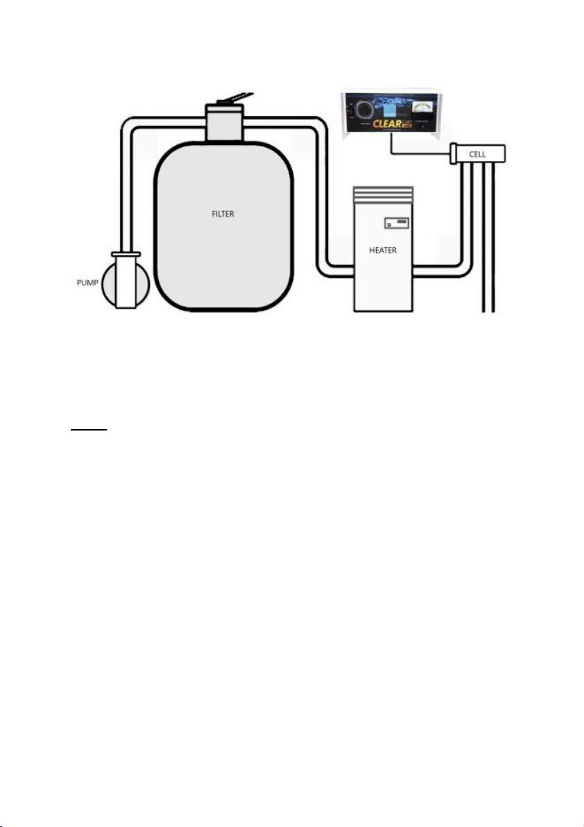
3. INSTALLATION OF THE CELL
Determine Filter Return to Pool Line.
a. Cell Housing must be in a horizontal position with inlet and outlet
sockets facing downwards as per diagram (refer page 9).
b. Cell must be installed after the heater (where fitted) and Solar
Systems (refer page 9). Pool cleaner pump motors that draw water
from the return to pool line should be fitted after the Cell for correct
pool chlorination.
c. CAUTION: It is very important that no gas generated from the Cell
can find its way back into the Filter, Pump, Heater, Solar Systems or
Spa Blowers.
d. When position of the Cell Housing has been decided, turn off the
Pump/Filter and CLOSE OFF VALVES if required.
e. If the Return to pool line is 40mm pipe, use 50-40mm reducing
bushes provided. If it is 50mm pipe, glue pipe directly into the inlet &
outlet ports on the cell housing.

9
4. POWER PACK / CELL CONNECTION
a. The Cell is supplied ready to connect to the Power Pack. Under the
Power Pack on the right side is the Cell Connection Point. Aline the
white arrows on the cell plug and connection point on the Power
Pack and push in until the outer blue locking ring “clicks” this will
indicate that the cell is plugged in correctly. To test pull on grey cell
lead and plug should not come out.
b. To disconnect cell twist outer blue locking ring anti clockwise and pull
down at the same time and the cell will disconnect.
NOTE: THE UNIT MAY MALFUNCTION AND CAUSE MAJOR DAMAGE IF THE
CELL PLUG IS INCORRECTLY PLUGGED IN AND WILL VOID ALL
WARRANTY OF CELL & POWER PACK.
5. PUMP / CHLORINATOR LEAD CONNECTION
a) Insert only one Pump Plug into 3 pin power socket underneath the
Power Pack.
b) Make sure Power switch on the unit is in the “OFF” position first then
insert Chlorinator Power Lead into a power point.
NOTE: THE UNIT HAS A 10 AMP PUMP SOCKET SO DO NOT PLUG MORE
THAN ONE PUMP INTO SOCKET. THE USE OF SOLAR CONTROLLERS,
POWER BOARDS & DOUBLE ADAPTORS THROUGH THE UNIT MAY
DRAW MORE THAN 10 AMPS WITH TWO PUMPS. THIS CAN CAUSE
MAJOR DAMAGE TO THE PUMP SOCKET AND WILL NOT BE
COVERED BY WARRANTY.

10
INSTALLATION DIAGRAM
NOTE: WATER MAY FLOW EITHER WAY THROUGH INLET/OUTLET PORTS
ON THE CELL HOUSING. (CELL MAY BE REVERSED AS SHOWN IN
DIAGRAM). GAS AND ELECTRIC HEATERS REQUIRE CELL INSTALLED
MINIMUM OF 1 METRE FROM HEATER OUTLET.
CHECK LIST BEFORE TURNING ON.
1. Pool Salt must be dissolved. (minimum 4000ppm)
2. Allow solvent cement to set before applying pressure (allow 24 hours).
3. Electrode is in Cell Housing with Locking Ring tight.
4. Suction Pool Cleaners are disconnected (For first Start Up only)
5. Skimmer Box & Pump baskets clean
6. Valves reopened.

11
OPERATION / START UP PROCEDURE
1. Turn on Mains Power supply.
2. Set Time Clock and operating times.
3. Set Pump Switch to “On” position.
4. Adjust Chlorine Level Knob to normal green sector after starting up pool
pump and this has run for 2 minutes by turning control knob clockwise
until chlorine monitor/gauge needle reaches the area of the green
section. This could be on the right or left of the monitor/gauge depending
on which polarity the unit is on.
NOTE: DON’T CONTINUE TURNING KNOB SO THAT NEEDLE GOES INTO THE
RED SECTION OR THIS WILL CAUSE DAMAGE TO THE UNIT WHICH
WILL NOT BE COVERED BY WARRANTY.
5. Once the unit has been set, switch Pump Switch to “Auto” position.
6. Pump and Chlorinator will commence operation when the time-clock
setting reaches “ON” positions that have been set on time clock.
NOTE: You may notice dim blue flashing within the chlorinator during
operation at night. This indicates normal operation.
SETTING THE TIMER
This 24-hour timer controls the
Pump / Filter and Chlorinator
which is switched ON and OFF by
the position of the coloured
tappets (White or Yellow
depending on age of unit). The
chlorinator / pump is ON when the
white triangle points to the
tappets that have been pushed to
the outer perimeter of the time
face and OFF when the white
triangle points to the tappets that
are closer to the numbers on the
timer face. Each tappet
represents 15 minutes.
The tappets are simply pushed towards the outer perimeter of the timer face
to program the desired chlorination time periods. (The white triangle is
located at the 2 o’clock position and should be pointing to current time.)
“AUTO” - for normal operation.
“ON” - for continuous running (overrides timer).
“OFF” - Pump / Chlorinator will cease to operate.
NOTE: IF UNCLEAR REGARDING SETTING TIMER CONTACT AWARD POOLS.

12
UNDERSTANDING THE CHLORINE MONITOR
Allow at least 7 DAYS on your pumping program for the pool and cell to
“settle in” before placing reliance on the monitor as certain slow chemical
changes take place in the initial salt charging.
This Chlorine Monitor is the “CENTRE ZERO” type. For no output to the cell
the needle needs to be in the vertical, CENTRE position. The meter alternates
between the (+) and (-) positions for each alternate output cycle indicating
the polarity of the cell. The cycle time is around 3 hours and the units monitor
will move from one side to the other. The unit produces chlorine on both
sides.
When the Chlorine Control knob is turned to maximum (clockwise) the
following Needle should be:
3000 ppm = B SECTION SALT LOW NOT RECOMMENED
4000ppm = C SECTION RECOMMENDED POSITON
5000ppm = D SECTION RECOMMENDED POSITON
Above 5000ppm = E SECTION SALT HIGH NOT RECOMMENED
There will be some variance in needle position due to temperature of water
and age of the Electrode.
If your Salt level is above 5000ppm and water temperature is above 25’
Degrees and the needle is only reaching B section this is an indicator that the
Electrode may need to be replaced.
The Chlorine Monitor presents a visual
indication of the chlorine production of
your Clear Care Chlorinator. Because this
is an Analogue Meter and is connected to
the cell wires it gives a TRUE reading of
chlorine production. If the Meter is in the
Green Sections while on it is producing
Chlorine

13
The Award Pools “Clear Care” chlorinator is available in 2 Models to suit the
capacity of your pool. This capacity is related to details on the label fixed to
the front of the Power Pack.
A50 for pools approximately 50,000 litre Capacity.
A100 for pools approximately 100,000 litre Capacity.
Each level is divided into coloured areas. YELLOW, GREEN, RED (see colour
coding in lower left-hand corner of meter) and the monitor needle position
will vary according to the condition of your pool and cell. i.e. Salt Content,
Pool Water Temperature position of Chlorine Control Knob and the condition
of the cell (age of cell & Cleanliness of Cell) which is an electrolytic generator
of chlorine.
The letters A to E, at the top of the scale of the monitor are a further
reference relating to the indicator needle position within a coloured sector.
A summary of the above information will be indicated as in the following:
YELLOW -AB 1. Calcium deposit on cell electrodes and or
2. Salt level below 3500 ppm has lowered (page 13 and or
3. Very low pool temperature.
GREEN - CD at 4000ppm –5000ppm Normal operation
RED - E High output from your chlorinator due to
1. Higher water temperature (heated pool) and or
2. Salt level over 5000 ppm.
3. Running Unit in this Level will cause damage to
Transformer, Triacs, and internal wiring and will void
warranty.
NOTE:THE CHLORINE MONITOR IS FACTORY CALIBRATED AT 25 DEGREES
CELSIUS WATER TEMPERATURE. HIGHER TEMPERATURES WILL
INCREASE NEEDLE SETTING INTO RED SECTOR.

14
GENERAL INFORMATION ON WATER CARE
A basic knowledge of pool-care fundamentals will allow some insight in
to the function of the various pieces of equipment and chemicals used
in and around your pool.
The four fundamental requirements in maintaining a pool or any body
of water are:
1. Adequate Filtration
2. Sufficient Chlorination
3. Proper pH control.
4. Chlorine Stabiliser i.e. Isocyanuric Acid (Except Indoor Pools)
FILTRATION
It is necessary to pass water through a filter to remove the debris. A powerful
pool pump with normal filter pressures) will pump approximately 10,000 litres
an hour. Normal pool practice demands that the entire pool capacity passes
through the filter at least one and a half times (1½) per day. This is normally
achieved in a six to ten-hour filtration cycle to remove 60% of the debris in
the water. The longer the filtration cycle the better the clarity and polish in
the water. However, if the pool is not being used i.e. winter Excessive
filtration & Chlorination causes excessive chlorine levels. And this causes cell
wear and reduces cell life.
CHLORINATION
Chlorine is required to react with the debris, removing stains by oxidation and
to sterilize the water of harmful bacteria. Chlorine residual, or reserve, is
required depending on bather loading. Normally if 1 ppm of chlorine is
introduced, then one and one half (1½) filtration cycles of the pool water will
leave the water in a clean clear condition.
Clear Pool water is achieved only with Good Filtration, Chlorination &
Correct Water Chemistry i.e. pH balance (7.2 –7.6).

15
PH
The acid/alkaline balance of water is measured using the pH scale. PH 14 is
alkaline, 0 is acid and 7 is neutral. PH control is the third essential element to
good pool care. Within the pH range of 7.0 to 8.0 chlorine will work as a
bleach and sterilizer and the precipitates formed will be at their maximum
size. A pH above 8.0 is too alkaline and will cause skin rashes and below 7.0
will sting sensitive tissue due to acidity. The pH range for the all Chlorinators
is 7.2 to 7.6.
The Langelier Index calculation table (below) can be used to check the water
balance of a pool. Readings of pH, water temperature (TF), calcium hardness
(HF) and total alkalinity (AF) are needed. These readings are used to obtain
the corresponding factor readings from the table (below) and then, to
perform the Langelier Index calculation.
For example, if pool water had the following values; pH 7.4, temperature
24°C, calcium hardness 100 ppm, and total alkalinity 200 ppm, then the
Langelier Index calculation would be worked out as follows:
Start with pH +7.4
Add TF +0.6
Add HF +1.6
Add AF +2.3
Subtract (K=12.1) -12.1
Langelier Index = 0.2
If the result is between -0.2 and +0.2, then the pool water is in balance.
If the result is lower than -0.2, then the pool water is corrosive.
If the result is higher than +0.2, then the pool water is scale-forming
LANGELIER INDEX CALCULATION TABLE
Pool Water
Temperature
Temp
Factor
Calcium
Hardness
Hardness
Factor
Total
Alkalinity
Alkalinity
Factor
(°C)
(TF)
CaC03
HF
C03
AF
0
0.0
5
0.3
5
0.7
3
0.1
25
1.0
25
1.4
8
0.2
50
1.3
50
1.7
12
0.3
75
1.5
75
1.9
15
0.4
100
1.6
100
2.0
19
0.5
150
1.8
150
2.2
24
0.6
200
1.9
200
2.3
29
0.7
300
2.1
300
2.5
34
0.8
400
2.2
400
2.6
40
0.9
800
2.5
800
2.9

16
The pool water passing over the cell should always be in balance relating to
the Langlier Index for a pH of 7.2 to 7.6.
NOTE: CONTINUAL RUNNING OF THE UNIT WITH A PH HIGHER THAN 7.8
AND FREE CHLORINE OF >5.00PPM WILL CASUE CELL DAMAGE AND
VOID ALL CELL WARRANTY.
CONCLUSIONS
It follows then that your pool must have an adequate circulation, chlorination
and filtration systems and the pH should be in the correct range.
The use of Chlorine Stabilizer (isocyanuric acid) in hot weather is essential to
help keep a residual of chlorine in the pool.
If your chemical balance is incorrect or if your Skimmer Box & Pump Baskets
are blocked or your variable pump speed is set to low this will cause slow
water flow over the cell and cause calcium to build up on your cell. The
Chlorinator will turn off (your pump will keep running but there will be NO
Chlorination so your pool will go Green & Cloudy. Then please perform the
following:
1. Clean the cell –refer page 15.
2. Clean Skimmer Box & Pump Baskets
3. Backwash Pool
4. Adjust Variable Pump Speed to increase water flow
5. Add Lo-Chlor Scale Eliminator.
6. Set the chlorine level control (in the GREEN section)–refer page 12-13.
7. IF CHLORINE IS LOW AND CHLORINE MONITOR IS IN THE YELLOW
SECTION TURN CHLORINE CONTROL KNOB AND MOVE NEEDLE TO
GREEN SECTION. DON’T TURN CHLORINE CONTROL KNOB SO CHLORINE
MONITOR IS IN RED SECTION IF CHLORINE IS LOW.
IMPORTANT: To ensure maximum auto-cleaning efficiency you must
ensure you operate your equipment as follows:
DO NOT TURN OFF POWER TO THE UNIT.
a) Minimise the frequency of adjustments of the chlorine level.
b) If you need to add chlorine during peak bathing periods or high-
water temperatures, use liquid chlorine ONLY.

17
MAINTENANCE
Before performing pool maintenance, vacuuming etc. Ensure that the timer is
not, and will not, be supplying power to the chlorinator during maintenance
period (refer setting of timer –page 10.
1. Turn the Chlorine Level Control to minimum –off –position, fully
anticlockwise. (Chlorine Monitor should be in Vertical Position when fully
turned down)
2. To turn power off to the pump, turn the Pump Switch to the “OFF”
position.
After completion of maintenance.
1. Turn the Pump Switch from the “OFF” position to the “ON” position run
for 2 minutes.
2. Readjust the Chlorine Level Control to normal GREEN Sector
3. Then turn the Pump Switch from “ON” position back to “AUTO” position.
4. The unit is now back to its normal operating mode.
BACKWASHING FILTER
The chlorinator Chlorine Level Control must be turned to the minimum
position when backwashing (manually) for long periods or when vacuuming to
waste.
POWER PACK
Provided the Power Pack is installed as instructed, no maintenance is
required. However, it should be kept clean and inspected regularly for
spiders, ants etc.

18
CELL
All our cells use only the highest quality De Nora electrode material
Manufactured in U.S.A.
At the beginning of each summer and at the end of the swimming season you
should remove the Electrode from cell housing and clean if there is any
calcium build-up on the plates.
1. If higher than normal calcium levels are present in the pool water,
electrodes may require manual cleaning on occasions.
a) Switch off the filtration and Chlorinator and close valves –leave
mains power on.
b) Unscrew cap in an anti-clockwise direction.
c) Remove electrode from Cell Housing and soak electrodes in hot
water and detergent.
d) If ineffective, mix one part of Hydrochloric Acid to 15 parts of water.
(Add acid to water) or Cell Cleaning Solution. Immerse cell until
clean and then remove immediately, don’t let cell sit in solution
without any calcium on it as minimal time in the solution is best for
long cell life. Rinse in fresh water after cleaning before returning to
housing.
e) If you are having to clean your cell more frequently than every 3
months your water balance may not be correct. Your Chlorinator cell
life may be reduced from frequent cleaning and is not covered under
warranty.
f) Insert electrode back into Cell housing, ensuring locating lug is at top
of cell, and O-ring is in place and tighten screw cap in a clockwise
direction
g) Lubricate “O” ring using only silicon grease if required.
h) DO NOT USE VASELINE
i) Open valves turn on filtration and chlorinator.

19
ADDING SALT
Use only refined pool salt. The Chlorinator is designed to run at 4,000 ppm –
lower than 3,500ppm and higher than 5000ppm will cause problems with
your chlorinator and may void electrode warranty.
1. SALT SHOULD NEVER BE ADDED UNLESS A WATER TEST IS PERFORMED
2. Determine salt requirements.
3. Ensure that the Chlorine Control knob is turned to the minimum –OFF –
position fully, anticlockwise.
4. Add salt into the shallow end of the pool.
5. Brush in salt to dissolve.
6. Re-adjust the Chlorine Level Control to normal GREEN Sector.
7. For best results test your pool water weekly. And tested by Pool Shop
every 4-6 weeks. You may find that it will require a bag of Salt every 2nd
Pool Shop water Test. On average a 50000L Swimming Pool will use 5 to
7, 20kg Bags of Salt in a year.
8. SALT LEVELS OF SWIMMING POOL WATER ARE NORMALLY TESTED WITH
A CONDUCTIVEITY METER / SALT METER AND THERE CAN BE VARANCE
OF +/- 500PPM WHEN TESTING.
SALT CHART
Parts per million Salt
500
1000
1500
2000
2500
3000
3500
4000
4500
5000
5500
5000
2.5
5
7.5
10
12.5
15
17.5
20
22.5
25
27.5
10,000
5
10
15
20
25
30
35
40
45
50
55
15,000
7.5
15
22.5
30
37.5
45
52.5
60
67.5
75
82.5
20,000
10
20
30
40
50
60
70
80
90
100
110
25,000
12.5
25
37.5
50
62.5
75
87.5
100
112.5
125
137.5
30,000
15
30
45
60
75
90
105
120
135
150
165
40,000
20
40
60
80
100
120
140
160
180
200
220
45,000
22.5
45
67.5
90
112.5
135
157.5
180
202.5
225
247.5
50,000
25
50
75
100
125
150
175
200
225
250
275
*60,000
30
60
90
120
150
180
210
240
270
300
330
65,000
32.5
65
97.5
130
162.5
195
227.5
260
292.5
325
357.5
70,000
35
70
105
140
175
210
245
280
315
350
385
75,000
37.5
75
112.5
150
187.5
225
262.5
300
337.5
375
412.5
80,000
40
80
120
160
200
240
280
320
360
400
460
Kilograms of Salt

20
WARRANTY
For a period of 36 months from the date of purchase the manufacture
warrants to the original purchaser that the CLEAR CARE CHLORINATION UNIT
shall be free from defects in materials and workmanship. This warranty covers
DOMESTIC USE ONLY.
The Cell carries an additional 36 month *pro rata replacement warranty.
Commercial installations are for 12 months ONLY on Power Pack and Cell with
no pro rata provision on the Cell. The Warranty shall be void if the unit’s case
or cabinet be opened or altered or modified during this period. If a defect
should occur the unit must be returned to manufacture or place of purchase
and PROOF OF PURCHASE presented.
Purchases sole and exclusively remedy in the event of defect is expressly
limited to correction of the defect by adjustment, repair or replacement at
the manufacturers’election and sole expense, except there shall be no
obligation to repair items which by their nature are expendable. Such items
include electrodes and rectifier devices.
The manufacture shall not be liable for loss of profits or benefits, indirect,
special, consequential, or other similar damages arising out of any breach of
warranty of otherwise.
PLEASE NOTE: LABOUR AND OR SERVICE CALLS ARE NOT INCLUDED IN THIS
WARRANTY.
No replacement parts will be supplied prior to the return of any faulty parts.
Freight on returns is the responsibility of the purchaser.
If a Warranty claim is lodged for a replacement cell in the first Three years
before a cell can be supplied the old cell must be returned to manufacture
with a minimum of 8 water tests over a 12-month period with no greater time
between tests than 2 months. If this cannot be provided a cell can be
purchased at the 37 months pro rata price.
This manual suits for next models
1
Table of contents
Popular Water Filtration System manuals by other brands

Ispring
Ispring RCS5T Installation instructions & user manual

Pentair
Pentair OMNIFILTER QUICK CONNECT T600RO Frequently asked questions

Lenze
Lenze 9400 Series Mounting instructions

Pentair
Pentair FLECK 3900 NXT Installer manual

Insignia
Insignia NS-SSHQ531 Quick setup guide

Vortec
Vortec 29625 Operation & Safety Instructions

solberg
solberg FS-05-025 Maintenance manual

aero-stream
aero-stream AS450-2 Installation and operator's guide

Glacier bay
Glacier bay HDGMBS4 Use and care guide

Pondmaster
Pondmaster Clearguard 2700 Care and operating instructions

ACO Haustechnik
ACO Haustechnik LipuSmart-P User instructions

Atlantic Ultraviolet
Atlantic Ultraviolet Bio-Logic BIO 1.5 Installation operation & maintenance