MIO 4n4n
P.P.H.U. AWEX Rafał Stanuch
ul.Długa 39, Masłomiąca
32-091 Michałowice
tel:+48 12 681 55 00
fax:+48 12 681 55 22
www.awex.eu
OGÓLNE WARUNKI GWARANCJI dostępne są na stronie internetowej producenta www.awex.eu
Zamówiony towar wyprodukowany wg indywidualnego zamówienia odbiegający od standardowej oferty firmy Awex nie podlega zwrotowi.
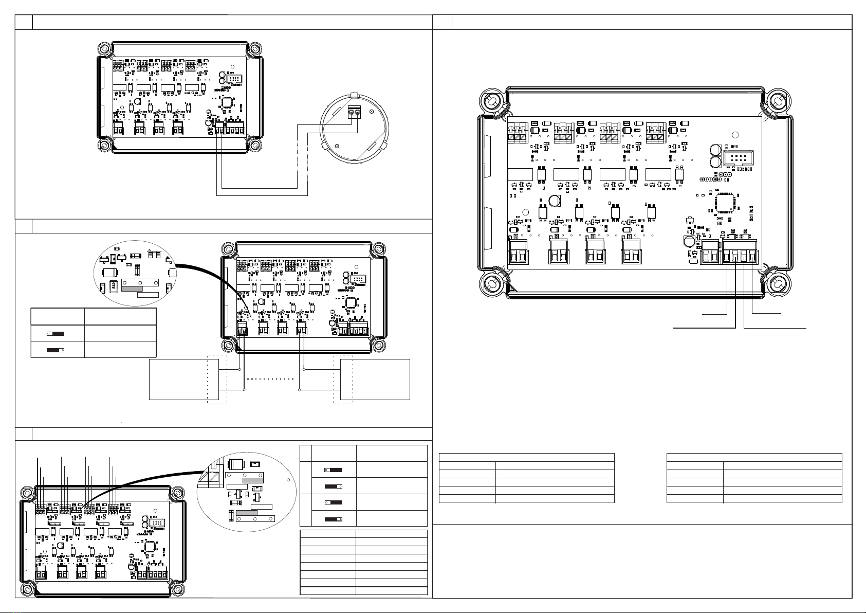
2MODUŁ MIO 4n4n S IP67
1MODUŁ MIO 4n4n O IP66
GENERAL CONDITIONS OF WARRANTY are available on manufacturer's website at www.awex.eu
The goods ordered that were manufactured according to the individual order and differ from the standard offer of Awex may be not returned.
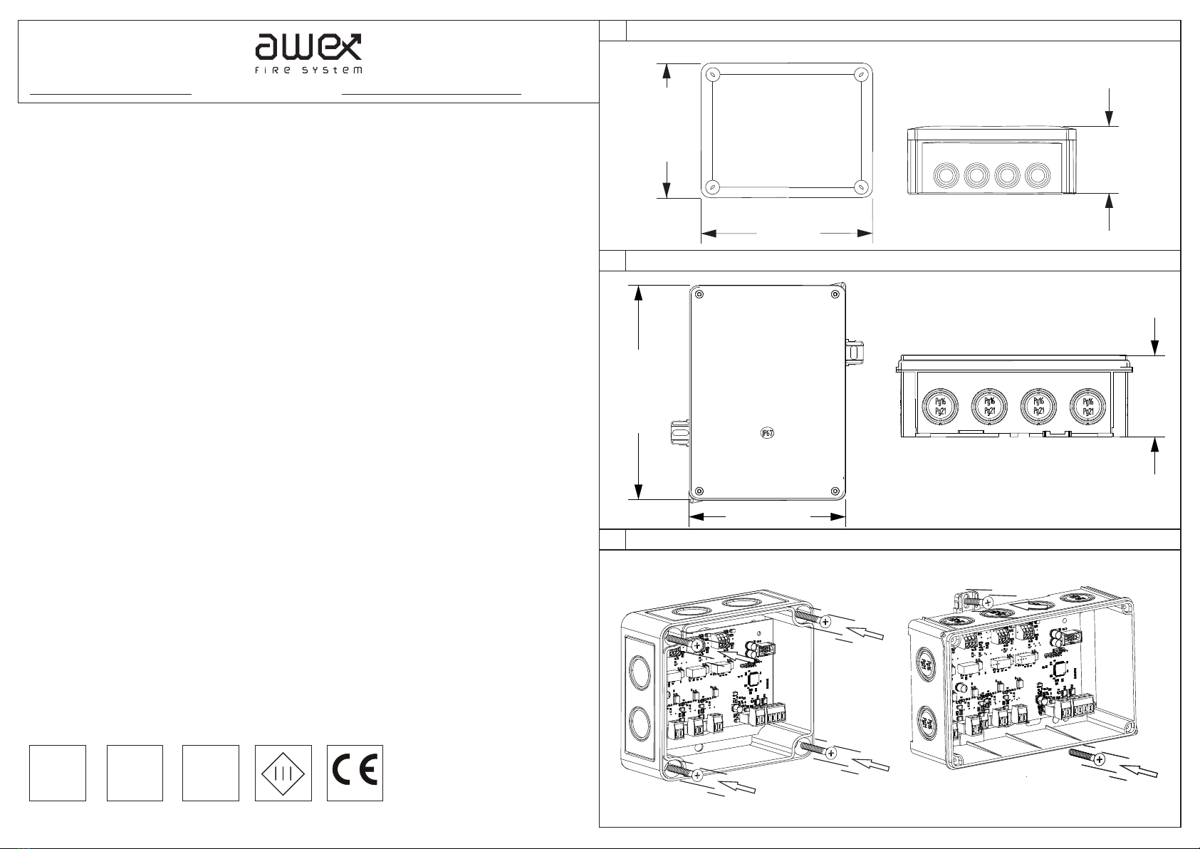
190 mm
77 mm
150 mm
3MONTAŻ MODUŁU DO ELEMENTU KONSTRUKCYJNEGO
118 mm
187 mm
67 mm
SPECYFIKACJA TECHNICZNA:
- Napięcie zasilania: 17 - 30 V DC
- Pobór prądu w dozorowaniu: <200µA*
- Pobór prądu w alarmie: <500µA*
- Obciążalność styków AC: 2A, 250V, 60W*
DC: 2A 220V, 60W*
- Zakres monitorowanego napięcia na wyjściu
LO: 9 - 220V DC / HI: 77 - 220V DC / HI: 60 - 250V AC
- Zakres napięcia aktywacji wejścia
LO: 9 - 220V DC / HI: 77 - 220V DC / HI: 60 - 250V AC
- Izolator zwarć: wbudowany, obustronny
- Temperatura pracy: od -10°C do 55°C
- Stopień ochrony: IP 66/67*
- Kolor obudowy: szary
- Wymiary: 190x150x77 mm / 187x118x67 mm
CECHY CHARAKTERYSTYCZNE:
- Wyrób zgodny z normą EN 54-18:2005/AC:2007
- Wyrób zgodny z normą EN 54-17:2005/AC:2007
- Wyrób stosowany w budownictwie
- Wyrób przeznaczony do systemów sygnalizacji pożarowej
- Wejścia potencjałowe
- Wyjścia bezpotencjałowe NO/NC nadzorowane
- Funkcja FAIL-SAFE
- Korpus urządzenia wykonany z poliwęglanu
Aby zapewnić prawidłową i bezawaryjną prace należy
przestrzegać następujących zasad
- Urządzenie może współpracować jedynie z centralą FAS
- Instalację modułu powinna wykonywać osoba uprawniona
do takich czynności oraz posiadająca odpowiedni certyfikat
- Minimum raz w roku należy przeprowadzić udokumentowany
przegląd techniczny elementu
- Zabrania się wprowadzania jakichkolwiek zmian w konstrukcji
układu elektronicznego oraz mechanicznego urządzenia
WARUNKI GWARANCJI:
Warunkiem uznania gwarancji jest:
- Brak uszkodzeń mechanicznych
- Brak śladów ingerencji osób trzecich w konstrukcję elementu
- Prawidłowa eksploatacja zgodna z zaleceniami
- Prawidłowe podłączenie przewodu kontrolno-zasilającego
TECHNICAL SPECIFICATION:
- Supply voltage: 17 - 30 V DC
- Current consumption in monitoring mode: <200µA*
- Current consumption in alarm mode: <500µA*
- Contact load capacity AC: 2A, 250V, 60W*
DC: 2A, 220V, 60W*
- Output voltage monitored range:
LO: 9 - 220V DC / HI: 77 - 220V DC / HI: 60 - 250V AC
- Input voltage activation range
LO: 9 - 220V DC / HI: 77 - 220V DC / HI: 60 - 250V AC
- Short-circuit isolator: integrated, double-side type
- Working temperature: -10°C to 55°C
- Protection class: IP 66/67*
- Housing colour: grey
- Dimensions: 190x150x67 mm / 187x118x67 mm
CHARACTERISTICS:
- Compliance with EN 54-18:2005/AC:2007
- Compliance with EN 54-17:2005/AC:2007
- Used for building industry
- Designed for fire detection and alarm systems
- Potencial inputs
- Monitored potential-free outputs NO/NC
- FAIL-SAFE function
- Polycarbonate housing
In order to ensure correct and failure-free operation,
the following rules must be followed:
- Use only with FAS units
- Installation of the module can be only performed
by qualified and certified personnel
- Perform documented inspections of the device
at least every year
- No modifications to the electronic or mechanical
elements can be made
WARRANTY CONDITIONS:
- Requirements for warranty service acceptance:
- No mechanical damage
- No signs of unauthorized modifications of the device
- Correct use acc. to manufacturer's recommendations
- Correct connection of the control and supply cable
INSTRUKCJA MONTAŻU ASSEMBLY INSTRUCTIONS
IN/OUT
24V
DC IP 66/67*
Certyfikat nr / Certificate No.: 1438-CPR-0519
DoP nr / DoP No.: 17/FS/2018/PL
HAUSING COVER OF MIO 4n4n O IP66
HAUSING COVER OF MIO 4n4n O IP67
INSTALATION OF THE MODULE TO THE STRUCTURAL ELEMENT
zalecane kołki / recomended rawlplugs Ø6
18
* cecha nie potwierdzona podczas oceny i weryfikacji stałości właściwości
użytkowych prowadzonej przez CNBOP-PIB
* feature not confirmed during the assessment and verification
of constancy of performance carried out by CNBOP-PIB
Dane techniczne: DTR MIO 4n4n v18.1
Technical data: UM MIO 4n4n v18.1