11/13
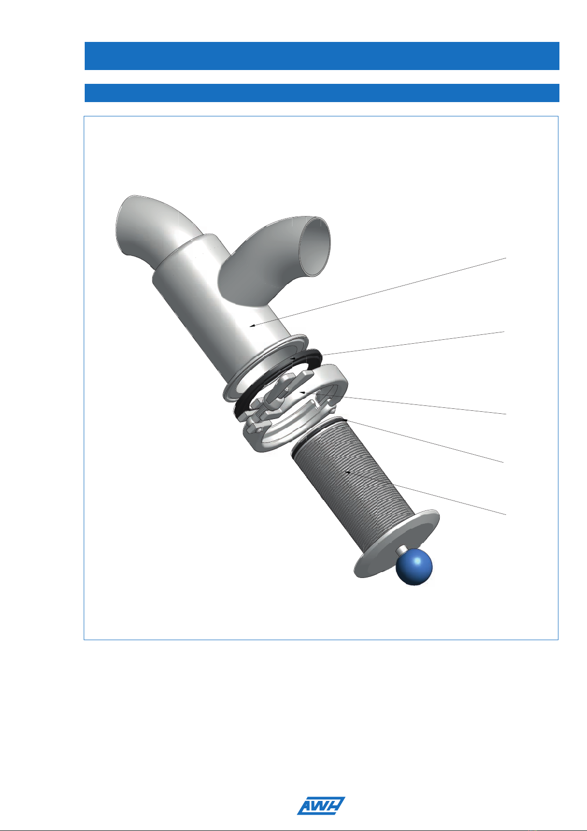
Dirt Trap - Type: DN25 - DN100 / PN10
Operating Instructions
Guideline/ standard Title Version Comments
DIN EN 62079 Preparation of instructions - structuring,
content and presentation
2001
97/23/EC EC Pressure Equipment Directive 2003
DIN EN 12516-2 Industrial ttings – Shell design strength
- Part 2: Calculation method for steel
tting shells
10/2004
AD 2000 data sheets Speci cations for pressure equipment
(national standards)
The ttings are designed for liquids of uid group 1 and for gases of uid group 2. According to this,
the nominal diameters are categorised as DN25 – DN100 in accordance with article 3, section 3.
2006/42/EC EC Directive: Machinery 2006
DIN EN ISO 12100 Safety of machinery -
General principles for design -
Risk assessment and risk reduction
2010
AWH Armaturenwerk Hötensleben GmbH
Schulstraße 5 - 6
D-39393 Hoetensleben
Declaration of Installation
as required by the
-EC Directive: Pressure Equipment Directive 97/23/EC, Annex II A
- EC Directive: Machinery 2006/42/EG, Annex II B
We hereby declare that design of
Description: Dirt Trap
Type: DN25 - DN100 / PN 10
in its delivered version is consistent with the listed directives and standards
(harmonised standards in accordance with the directives):
5
1.3 Declaration of Installation
If any modi cations are made to the non-return valve without our agreement, this declaration is void.
Note:
Commissioning is prohibited until it is certain that the overall system fulfi ls the provisions of the
directives. For information about proper use of the fi ttings, see the operating instructions.
Hoetensleben, of October 24th, 2013
..............................................................................
Thomas Erhorn / CEO
Person authorised to compile the technical documentation:
Armaturenwerk Hötensleben GmbH
Mr. Guth, Schulstr. 5 - 6, D-39393 Hoetensleben
Hoetensleben, of October 24th, 2013
..............................................................................
Person authorised to compile the technical documentation: