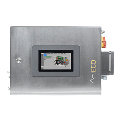
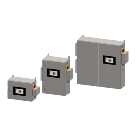
Awite AwiFLEX XL User guide

PART A: PRODUCT DESCRIPTION,
INSTALLATION AND OPERATION
AWIFLEX XL
AWITE
BIOENERGIE
Original Instruction Manual
(Version: 18.0)

Contact and Imprint
Please find the latest information online at www.awite.com . For any questions, comments or
suggestions, please send an email to [email protected] .
Awite Bioenergie GmbH
Grünseiboldsdorfer Weg 5
85416 Langenbach/Niederhummel, Germany
Phone: +49 8761 / 72 162 - 0
Fax: +49 8761 / 72 162 - 11
Email: [email protected]
http://www.awite.com
© 2022 Awite Bioenergie GmbH
Errors and changes reserved
2

Table of Contents
Table of Contents
1 Preface................................................................................................................................................6
2 Identification......................................................................................................................................7
3 Safety Instructions Part A.................................................................................................................8
4 Product description........................................................................................................................12
4.1 Intended Usage............................................................................................................ 12
4.2 Device Category According to ATEX Classification................................................ 13
4.2.1 Device category not intended for installation in an Ex-zone..................................13
4.2.2 Device category intended for installation in an Ex-zone 2..................................... 13
4.2.2.1 Safety device for monitoring the interior space.......................................................14
4.3 Description of the Gas Analysis System and Dimensions.......................................15
4.4 Ambient Conditions and Limits for Operation and Storage...................................18
4.4.1 Installation location...................................................................................................... 18
4.4.2 Installation height......................................................................................................... 18
4.4.3 Ambient Temperature..................................................................................................18
4.4.4 Ambient humidity.........................................................................................................18
4.4.5 Mains voltage fluctuations...........................................................................................18
4.4.6 Overvoltage category.................................................................................................. 19
4.4.7 Wetness and degree of pollution in the environment............................................ 19
4.4.8 Measuring gas pressure.............................................................................................. 19
4.4.9 Measuring gas, fresh air and exhaust air requirements.......................................... 19
4.5 Hazards from gas..........................................................................................................20
4.5.1 Zone division.................................................................................................................20
4.5.2 Flame or explosion propagation over gas bearing lines........................................20
4.5.3 Leakage in the Measuring Gas Supply Line............................................................. 21
4.5.4 Gas volume....................................................................................................................21
4.5.5 Leaks in the Gas Analysis System...............................................................................21
4.5.6 Release of Potentially Toxic and Harmful Gases.......................................................21
5 Preparing the Gas Analysis System for Use................................................................................23
5.1 Transport and Storage................................................................................................. 23
5.2 Installation......................................................................................................................23
5.2.1 Main Switch Mains Disconnection Facility.................................................................24
5.2.2 Terminal boxes for electrical connections.................................................................24
5.2.2.1 Terminal Boxes AwiFLEX XL........................................................................................25
5.2.2.2 Connection Cable 100–240 V for Power Supply...................................................... 25
3

Table of Contents
5.2.2.3 Connection cable for DI (digital inputs) and DO (digital outputs).........................25
5.2.2.4 Connection cable for AI (analogue inputs) and AO (analogue outputs)...............26
5.2.3 Potential equalization...................................................................................................26
5.2.4 Data transmission of signals....................................................................................... 27
5.2.4.1 Profibus...........................................................................................................................27
5.2.4.2 Analogue outputs.........................................................................................................28
5.2.5 Information on Cable and Lines Routing.................................................................. 28
5.2.6 Connection of analysis gas lines................................................................................ 29
5.2.6.1 Extraction Points for Analysis Gas.............................................................................. 29
5.2.6.1.1 Gas extraction fitting unpressurized and up to 400 mbar..................................... 29
5.2.6.1.2 Gas extraction fitting up to 16bar (PN16)................................................................31
5.2.6.2 Laying of Analysis Gas Lines.......................................................................................32
5.2.6.3 Gas Inlets AwiFLEX XL.................................................................................................33
5.2.6.4 Exhaust air – Discharge of the Measuring Gas.........................................................34
5.2.7 Installation of Humidity and Flow Sensor AwiFLOW............................................... 35
5.2.8 Initial Operation............................................................................................................37
6 Handling of the Gas Analysis System..........................................................................................38
6.1 Maintenance.................................................................................................................. 38
6.1.1 Cleaning.........................................................................................................................38
6.1.2 Calibration..................................................................................................................... 39
6.1.3 Hydrogen sulphide filter..............................................................................................39
6.1.4 Detonation Flame Arrester..........................................................................................39
6.1.5 Connecting Tubes.........................................................................................................39
6.1.6 Condensate traps......................................................................................................... 40
6.2 Replacing a Fuse.......................................................................................................... 40
6.2.1 Specification Fuse F1 (Input Voltage 100–240 VAC)............................................... 40
6.2.2 Specification Fuse F2 (Power Supply Unit Output Voltage 24 VDC)......................40
6.3 Spare Parts List..............................................................................................................40
6.4 Disposal..........................................................................................................................41
6.5 Product Liability............................................................................................................ 41
7 Technical Data and Sensor Accuracy.......................................................................................... 42
7.1 Technical Data...............................................................................................................42
7.2 Accuracy, Service Life and Calibration of the Sensors............................................ 42
8 AwiDESULF combi-package for microbiological desulphurisation.........................................45
8.1 Intended Usage............................................................................................................ 52
8.2 Assumptions for Interpreting......................................................................................52
4

Table of Contents
8.3 Required Space.............................................................................................................52
8.4 Mechanical Connection............................................................................................... 54
8.5 Electrical Connection................................................................................................... 55
8.6 Maintenance.................................................................................................................. 56
8.6.1 Check non-return valve and solenoid valve............................................................. 56
8.6.2 Procedure for checking the non-return valve and solenoid valve......................... 56
9 AwiLAB Gas analysis...................................................................................................................... 58
9.1 Required Space.............................................................................................................59
9.2 Mechanical Connection............................................................................................... 59
9.3 Electrical Connection................................................................................................... 59
10 AwiVac..............................................................................................................................................61
10.1 Required Space.............................................................................................................62
10.2 Assemblies in the AwiVac........................................................................................... 63
10.3 Mechanical Connection............................................................................................... 64
10.4 Electrical Connection................................................................................................... 65
11 AwiWarn...........................................................................................................................................66
11.1 Installation AwiWarn.....................................................................................................66
11.2 Required Space.............................................................................................................67
11.3 Electrical Connection................................................................................................... 68
11.4 Settings and calibration...............................................................................................69
12 Annex............................................................................................................................................... 70
12.1 Declarations of Conformity......................................................................................... 70
12.1.1 CE Declaration of Conformity for Devices Not Intended to be Installed in an Ex-
Zone................................................................................................................................71
12.1.2 CE Declaration of Conformity for Devices Intended to be Installed in an Ex-
Zone................................................................................................................................72
12.1.3 UKCA Declaration of Conformity for Devices Not Intended to be Installed in an
Ex-Zone...........................................................................................................................73
12.1.4 UKCA Declaration of Conformity for Devices Intended to be Installed in an Ex-
Zone................................................................................................................................74
12.1.5 IEC - Conformity Declaration......................................................................................75
12.2 Certificat TÜV SÜD UL - CSA 61010-1-2012.............................................................77
5

Preface
1 Preface
PLEASE READ THE INSTRUCTION MANUAL AND SAFETY INSTRUC-
TIONS CAREFULLY BEFORE INSTALLATION AND OPERATION!
This Instruction Manual provides you with information to assist you in using the gas analysis system. The
Instruction Manual is part of the product and has to be kept throughout the service life of the product.
When subsequently passing on the gas analysis system to a third party, the customer has to provide
the Instruction Manual along with it. The new owner of the system has to be trained in the regulations
referred to. If you receive an amendment to the Instruction Manual at a later stage, this amendment is
also part of the Instruction Manual.
The device may only be used in a technically perfect condition and for its intended use, with awareness
of safety aspects and possible hazards and in full adherence with the Instruction Manual. Please operate
and service your gas analysis system based on the information in this Instruction Manual.
The Instruction Manual for the Awite – Gas Analysis System consists of two parts:
Part A: Product Description, Installation and Operation
Part B: Operation
6

Identification
2 Identification
This Instruction Manual is intended for Awite Bioenergie GmbH gas analysis systems of the respective
series specified on the cover sheet. The type plate on the right hand side panel of the device indicates
the device type, the required voltage supply and the rated output.
The manufacturer's address is:
Awite Bioenergie GmbH
Grünseiboldsdorfer Weg 5
85416 Langenbach/Niederhummel, Germany
Phone: +49 8761 / 72 162 - 0
Fax: +49 8761 / 72 162 - 11
Email: [email protected]
http://www.awite.com
7

Safety Instructions Part A
3 Safety Instructions Part A
The device is only designed for situations of intended use. A non-intended use can lead to
personal injury and property damage. Only use the device as intended.
The device measures combustible or explosive gases and is installed in their environment. There
is a potential risk of spread or ignition of a hazardous atmosphere. Make sure to observe the rules
regarding explosion protection.
Line breakage, breakage of fittings and damage inside and outside the unit can lead to explosion
hazard and risk of poisoning. Regularly check pipes and fittings for changes (damage, corrosion,
brittleness, leaks, animal damage) or have maintenance carried out. Replace if necessary (use
only suitable materials and fittings).
Biogas contributes to the greenhouse effect and thus to climate change. If possible, do not
discharge gas into the atmosphere.
Excessive rated pressure on the gas analysis system can cause gas to escape. During shutdown,
when no gas is present at the sensors, the device can withstand a maximum of 2 bar overpressure
up to the first valve. If the system pressure at the gas extraction points is reduced by the
customer, it must be ensured that no more than 2 bar can reach the gas analysis system even in
the event of a fault.
Parts inside the device are under electrical voltage. Danger to life by electric shock! ALL
installation/repair/maintenance operations on the gas analysis system or on the whole plant
must only be carried out in a de-energized state and when the system is completely turned off.
Observe electrical safety regulations.
Biogas contains hydrogen sulphide. Gas leakage can lead to acute inhalation toxicity. At a
concentration of hydrogen sulphide of more than 22,000 ppm or room volumes that are less than
the standard container size (32 m³) or air exchange rates of less than once per hour, the risk of a
possibly even deadly poisoning caused by hydrogen sulphide needs to be assessed individually
and appropriate measures have to be taken. Avoid small room volumes and low air exchange
rates.
Carbon monoxide is odorless and toxic. In the event of a fault, it can accumulate in the device and
escape in a gush when it is opened. While opening the housing, ensure sufficient ventilation and
distance or monitor the environment for carbon monoxide.
An improperly performed installation, electric installation, initial operation, or maintenance of
the gas analysis system may cause hazards, especially due to gas and electrical current. These
activities must therefore only be performed by trained personnel. The specialist personnel must
have read and understood the Instruction Manual and follow its instructions.
8

Safety Instructions Part A
Hydrogen sulphide is toxic. Watch out for smell of rotten eggs. Ventilate the room and do not
enter.
Carbon monoxide is toxic. A suitable gas warning sensor must be used, unless the ventilation is
sufficient.
The main switch serves as a mains disconnection facility to shut down the function and avoid
hazards caused by electricity. The device has to be installed in such a way that the main switch
operation is not impeded.
In case of a defect, gas leakage may occur. In case of insufficient ventilation, even small amounts
can lead to a hazard (poisoning, explosion) over a longer period of time. The device must
therefore not be installed in unvented shafts or poorly ventilated rooms.
Different electrical voltages may be present at the terminals in the terminal box. An incorrect
connection will lead to malfunction and hazards arising from electrical current. For information
on the allocation of the different terminals or the wiring in the terminal box please refer to the
electric diagram provided as part of the system.
Combustible gas could enter the device through the exhaust gas line and create an explosive
atmosphere there. Therefore, lead the exhaust lines separately and directly to the outside and
have nothing discharge into the exhaust gas line. In case of analysis gas recovery, ensure the
exhaust gas line is not longer than 20 m and have it lead the exhaust gas only into gas-bearing
areas in which a maximum underpressure or overpressure of 20 mbar prevails.
Gas which may be toxic, flammable or explosive flows through the exhaust gas line. Therefore,
the exhaust gas must not be released inside the building unless there is appropriately sufficient
ventilation.
The device conveys combustible gas. A continuous stay in the immediate vicinity of the device
may lead to a statistically increased risk of explosion. Therefore, no persons are allowed to stay
permanently in the vicinity of the device.
To ensure the safe and correct operation of the process analysis system, regular maintenance
work is an absolute necessity, as during this process wearing parts (such as seals) are replaced
and the whole system is checked thoroughly. Failure to comply increases the risk by gas leakage
(danger of explosion). The maintenance interval must therefore be observed.
The state of the gas analysis system must be checked on a regular basis, error messages need to
be addressed. In the event of the error messages "potentially dangerous atmosphere" or "risk of
explosion" as well as with loose hose ends, porous hoses or other leaks that lead to an explosion
hazard, disconnect the device from the gas supply and shut it down. Contact Awite or an Awite
contract partner.
9

Safety Instructions Part A
The drain of the condensate trap is a secondary source of gas release. In case of poor ventilation,
a hazardous explosive atmosphere may arise. Therefore please make absolutely sure to close the
discharge tap after emptying the condensate traps.
The device contains fuses that are under electrical voltage. Danger to life by electric shock.
Replace the fuses only in a non-energized state. Observe electrical safety regulations.
The measuring point switch-over includes a diffusion opening to prevent the occurrence of a
dangerous atmosphere (explosion hazard) inside. Therefore check coarse dust filter for any dirt
on a regular basis and clean it in order to maintain its function.
Leakages in the AwiCONTAINER may create a hazardous atmosphere. The ventilation grilles are
important in order to dilute the air in case of leakages. These must not be closed.
Carbon monoxide is odorless and toxic. It can accumulate in the AwiCONTAINER. A poisoning can
be deadly. With carbon monoxide-containing gas, install a suitable CO gas alarm sensor.
Leaking fuel gas mixture may cause an explosion hazard in the AwiCONTAINER. Install an
electrocatalytic gas warning sensor, except for biogas with low leakage flow (pressure at
sampling point max 20 mbar) or low flammable gas concentration (less than 4 % v/v).
Gas warning sensors can deliver too low readings or even become unusable due to hydrogen
sulphide in the air. Calibrate gas warning sensors in according to manufacturer's recommendation
(every 6 months). If the ambient air contains hydrogen sulphide, shorten the calibration interval
(to 3 months).
Disconnecting the connection cable between the AwiLAB and the milligas counter or the drum
gas meter, respectively, during operation may lead to faulty controls. This can cause excessive
pressure in the connected collecting gas bags, which could then lead to damage and thus to gas
leakage. Before conversion work, the gas analysis system must be de-energized.
AwiDESULF: In order to avoid gas leakage via the air supply line and thus a risk of explosion, a
leakage test of the air supply line with non-return valve must be carried out after installation and
initial operation of the system.
AwiDESULF PureOxygen: Pure oxygen can react explosively with oil and grease. Do not use
lubricants and sealants containing oil or grease in pure oxygen or enriched air.
AwiDESULF: Hot surface on the compressor, thus risk of burns. Do not touch.
The gas analysis system contains icons with the following meaning:
10

Safety Instructions Part A
Attention, General Hazard Point. Refer to the documentation. Disregarding this can
lead to death or serious personal injuries or property damages.
Warning of dangerous electrical voltage.
Please also observe the safety instructions in Part B!
11

Product description
4 Product description
The following chapter contains information on the intended usage, the device category according
to the ATEX classification, the ambient conditions during operation and storage as well as safety
information.
4.1 Intended Usage
WARNING
The device is only designed for situations of intended use. A non-intended use can lead to
personal injury and property damage. Only use the device as intended.
The gas analysis systems serve as analytical device for air, biogas, sewage gas, biomethane as well
as hydrogen up to 100vol% and hydrogen sulphide up to 5vol%. They are neither part of explosion
protection nor a warning device. They are used without any additional pressure reducing measures
for measuring biogas with a maximum of 20 mbar of underpressure or overpressure. The suitability for
use in safety-critical applications must be assessed by the user for each case. Reliability data can be
provided by Awite if required.
WARNING
The device is installed in the vicinity of combustible or explosive gases. Operating a non-explosion-
protected device in a hazardous atmosphere can cause an explosion with personal injury and
property damage. Do not place the device in a dangerous atmosphere unless a corresponding
marking exists on its housing.
12

Product description
4.2 Device Category According to ATEX Classification
Applies only within the EU and in countries in which the ATEX Directive (2014/34/EU) also applies. The
ATEX marking is located on the left outside of the casing.
4.2.1 Device category not intended for installation in an Ex-zone
Marking per ATEX with
II 2/- G IIA
Gas-carrying pipes with inflammable or explosive gas of explosion group IIA (e.g. biogas) may be
connected to the device at the appropriate point (zone 2 or 1 in the interior of the line). The device itself
has to be installed outside of a hazardous atmosphere.
4.2.2 Device category intended for installation in an Ex-zone 2
Marking per ATEX and IEC EN 60079 with
II 2/3 G Ex nC ec IIA/IIC T1 Gc X
Gas pipes with combustible or explosive gas (zone 2 or 1 inside the pipe) may be attached to the device
at the designated and appropriate place. The suitable detonation arrester must be used with gas IIB or
IIC. The device itself may be installed in zone 2 gas IIC: Electrical connections must not be separated
under voltage. The volume inside the device must be detected by means of a suitable warning sensor
and the power circuits have to be disconnected from mains if necessary. The types of protection nC and
ec refer to the outside of the display and the integrated terminal box respectively.
13

Product description
4.2.2.1 Safety device for monitoring the interior space
A gas warning sensor of the ignition protection type
II 2G / EEx de IIC T4
for intended use as a safety or control device in order to detect methane / Zone 2 in accordance with
the requirements of Directive 2014/34/EU, sections 1.5.5 through 1.5.8 is available at Awite.
14

Product description
4.3 Description of the Gas Analysis System and Dimensions
The gas analysis system is located inside a stainless-steel wall cabinet. The space requirement and list
of the exterior and interior views are summarized in the table below. The cabinet is mounted to the wall
using four wall clips (see illustration for dimensions). There needs to be enough room in front of the
device for opening the door arrangement and for operating the device.
Table 1: Mounting Dimensions Gas Analysis System
Mounting dimensions [mm]Device type
Width Height Depth
AwiFLEX XL 975 900 268
The analysis gas lines are routed to the system from the left hand side via the condensate traps for the
manual emptying of the system. Pressure-resistant pipes are recommended as analysis gas lines:
– Diameter 4/6mm or 1/8“/¼“
– Material: stainless steel 1.4401 or highly resistant plastic (depending on the site of operation,
stainless steel pipes might be obligatory)
All connections on the condensate traps and on the gas analysis system are implemented as hose screw
or pipe screw connections for these pipe cross-sections. For protection purposes, the analysis gas lines
should be run through protective tubes.
15

Product description
Figure 1: AwiFLEX XL including condensate traps on the outside
The equipment shown here serves as an example, as the components are individually assembled
according to customer requirements.
1. Main switch
2. Terminal box
3. USB connection
4. RJ45
5. Profibus IN
6. Profibus OUT
7. Potential equalization
8. Measuring gas cooler AwiCool
9. Measuring gas cooler AwiCool (optional)
10. Exhaust air
11. External supply of analysis gas
12. Mounting brackets for 4 condensate traps
13. Condensate container gas cooler
14. Condensate trap analysis gas
15. Panel PC
16. Supply of fresh air
17. Connections for
– Measuring points
– Exhaust air
– Calibration gas
– Condensate from gas cooler
16

Product description
Figure 2: Assemblies in the
AwiFLEX XL gas analysis system
The equipment shown here serves as an example, as the components are individually assembled
according to customer requirements.
1. Main switch
2. Line filter
3. Fuse terminal 100–240 VAC
4. Terminals 100–240 VAC
5. Power supply unit
6. Fuse terminal 24 VDC
7. AwiProtect
8. Terminals 24 VDC
9. Relay group error
10. AwiCORE 1 (PLC module)
11. AwiCORE 2 (PLC module)
12. Measuring gas cooler AwiCool
13. Absolute Pressure Sensor
14. Oxygen sensor
15. Carbon monoxide sensor
16. diverse electrochemical sensor
17. Mounting brackets sensors
18. Multi-gas sensor InfraFRED
19. AwiConnect incl. pressure sensor
20. diverse electrochemical sensor
21. diverse electrochemical sensor
22. Filter AwiClean
23. Thermal conductivity sensor
24. Temperature sensor
25. Measuring gas cooler 2 AwiCool
26. Pressure filter
27. Membrane pump
28. Relative pressure sensor
29. Water sensor AwiH2O
30. Valves
31. Hydrogen sulphide filter
32. Profibus module
33. Relay AwiDESULF
34. Relay feedback motor protection
17

Product description
4.4 Ambient Conditions and Limits for Operation and Storage
Although the Awite gas analysis systems are designed for use under rough conditions, some
requirements concerning the location and environmental conditions should be met in order to obtain
a high accuracy of measurement and to avoid damaging the system. For the conditions not listed here,
the specifications from IEC Standard 60359 apply to application group 1.
4.4.1 Installation location
The system is intended for indoor use.
4.4.2 Installation height
The gas analysis system can be operated in areas which are located up to 2,000 mabove sea level
(normal height null, NHN).
4.4.3 Ambient Temperature
In the interior of the casing, the temperature can be 15 °C higher than the ambient temperature.
Therefore, the ambient temperature for the device must be between +5 °C and +35 °C in order to
guarantee an exact measurement of the sensors, not to damage the electronic components and to be
able to operate the unit safely. The analysis systems are calibrated at 25°C. All detailed specifications
refer to this temperature, any deviations that occur under significantly changed temperature conditions
are sensor-related.
CAUTION
The temperature inside the device can be up to 15°C higher than the ambient temperature.
Excessively high temperatures can lead to damage to components and reduce the service life of
sensors. Sub-zero (°C) temperatures can destroy electrochemical sensors. This affects the measuring
function and gas leakage can occur. Install the device in rooms with temperatures between +5°C and
max. 35°C. The temperature in the control box must not exceed 50°C . Do not install the device in the
hot exhaust air of cogeneration units.
4.4.4 Ambient humidity
The relative humidity must be kept between 0 and 80% .
4.4.5 Mains voltage fluctuations
Mains supply voltage fluctuations of up to ± 10 % of the nominal voltage are permissible.
18

Product description
4.4.6 Overvoltage category
Transient overvoltages are permissible up to the values of
OVERVOLTAGE CATEGORY II
These values for transient overvoltage are typical for devices that are supplied via the building
installation.
4.4.7 Wetness and degree of pollution in the environment
The gas analysis system complies with protection class IP 54 and is therefore dust- and splash-proof, but
is not intended for installation in wet environments.
The device is intended for installation in an environment with POLLUTION DEGREE 2.
This is only non-conductive pollution, although temporary conductivity caused by dew may be
occasionally expected.
4.4.8 Measuring gas pressure
The pressure in the measuring lines must be at atmospheric pressure ±20 mbar (normal operation).
Pressure outside this range is not allowed because the sensors may be damaged and measured values
may be changed. With higher or lower pressure, corresponding measures must be taken (pressure
regulator, precision pressure regulator, available from Awite).
NOTE
The highest rated overpressure inside the unit is 100 mbar in measuring mode and 2 bar in inactive
state (valve inside the device closed). Therefore, in measuring mode the pressure is monitored and
the device is stopped if 100 mbar is exceeded, in which case an error message is displayed.
4.4.9 Measuring gas, fresh air and exhaust air requirements
It has to be assured that no polluted flushing air or ambient air can be sucked in by the gas analysis
system and that the exhaust air hose remains free and unobstructed at all times.
CAUTION
Water, particles and dirt can clog pipes, sensors and valves. As a result, monitoring functions and thus
the measuring function can be impaired. Check the condensate traps daily.
19

Product description
When maintenance work is carried out on the gas pipe, the gas analysis system is to be switched off and
the ball valve at the measuring gas extraction point has to be closed.
WARNING
Work on the gas pipe may result in gas leakage. This creates a fire and explosion hazard. Switch off
the device during maintenance work and close the ball valve during gas sampling.
4.5 Hazards from gas
As the systems are used for the analysis of biogas and in a biogas system environment, the explosion
hazard has to be assessed prior to installation. A comprehensive risk assessment according to the
machinery directive is available from Awite. Technical data can be adapted to new technological
advances in the area of biogas by the manufacturer without any prior notice. Please contact Awite if
you need information about possible additions to this Instruction Manual and whether it is the current
version.
4.5.1 Zone division
Inside the measuring gas pipes and inside the gas analysis system there are only very small amounts of
gas, whose volume is far below hazardous amounts. Therefore no Ex-zone obtains in this case. Whether
there is an Ex-zone around the gas analysis system or its pipes or not depends on the probability of the
occurrence of an explosive gas mixture. The following describes the actions to be taken to avoid an
explosive atmosphere, which could arise due to the gas analysis system. If the following instructions are
taken into account, there will be no Ex-zone inside the gas analysis system or the feed pipes either.
4.5.2 Flame or explosion propagation over gas bearing lines
With gases belonging to explosion group IIA (methane, biogas), tube and pipe connections with an
internal diameter of 4mm have the same effect as a deflagration arrester (tested length of 11cm). As the
distance from the hose to the relevant ignition sources (sensors) is always less than 50 times the hose
diameter, there is no need for separate deflagration arresters between the analysis device and gas-
bearing lines with larger cross-section and hazardous atmosphere with the explosion group IIA and up
to zone 1. There is an inspection report of an approved ATEX test centre verifying this.
When measuring hydrogen at higher concentrations1 (special device); or with zone 0, a detonation
arrester must be installed as needed.
1Biogas with up to 10% hydrogen in the flammable gas portion remains in explosion group IIA (source: BG ETEM/
BAM research project Hydrogen Mixtures).
20
Table of contents
Other Awite Measuring Instrument manuals