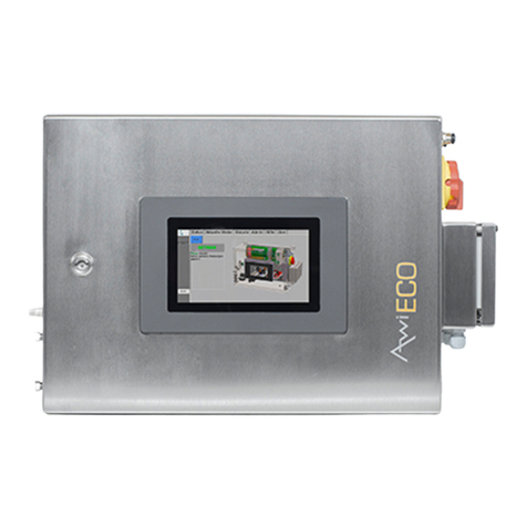
Awite 10 Series User guide

GAS ANALYSIS SYSTEM
SERIES 10
PART A: PRODUCT DESCRIPTION,
INSTALLATION AND OPERATION
Original Instructi n Manual
(Versi n 10.02)

2
C ntact and Imprint
Please find the latest inf rmati n nline at www.awite.de. F r any questi ns, c mments r
suggesti ns, please send an email t inf @awite.de.
Awite Bi energie GmbH
Grünseib ldsd rfer Weg 5
85416 Langenbach/Niederhummel, Germany
Ph ne +49 8761 72 162-0
Fax +49 8761 72 162-11
Email inf @awite.c m
http:// www.awite.de
© 2015 AWITE Bi energie GmbH
Err rs and changes reserved

3
1 Table f C ntents
1 Table f C ntents ................................................................................................................. 3
2 Preface ................................................................................................................................. 6
3 Identificati n ......................................................................................................................... 7
4 Safety instructi ns ................................................................................................................. 8
5 Pr duct Descripti n ............................................................................................................ 13
5.1 Intended Usage ................................................................................................. 13
5.2 Device Categ ry Acc rding t ATEX Classificati n ........................................... 14
5.2.1 Device categ ry n t intended f r installati n in an Ex-z ne .............................. 14
5.2.2 Device categ ry intended f r installati n in an Ex-z ne 2 ................................. 14
5.2.2.1 Safety device f r the m nit ring f the interi r space ....................................... 15
5.3 Descripti n f the Gas Analysis System and Dimensi ns ................................... 15
5.4 Ambient C nditi ns and Limits f r Operati n and St rage ............................... 23
5.4.1 Ambient Temperature ........................................................................................ 23
5.4.2 Ambient Humidity ............................................................................................. 23
5.4.3 Installati n Height ............................................................................................. 23
5.4.4 Humidity and dust ............................................................................................. 24
5.4.5 Measuring gas pressure ..................................................................................... 24
5.4.6 Measuring gas, fresh air and exhaust air requirements ...................................... 24
5.4.7 Calibrati n Gas C nnecti n ............................................................................... 25
5.5 Hazards fr m gas ............................................................................................... 25
5.5.1 Z ne divisi n ..................................................................................................... 26
5.5.2 Flame r expl si n pr pagati n ver gas bearing lines .................................... 26
5.5.3 Leakage in the Measuring Gas Supply Line ....................................................... 26
5.5.4 Gas v lume ....................................................................................................... 26
5.5.5 Leaks in the Gas Analysis System ....................................................................... 27
5.5.6 Release f P tentially T xic and Harmful Gases ................................................. 28
6 Preparing the Gas Analysis System f r Use ......................................................................... 29
6.1 Transp rt and St rage ....................................................................................... 29
6.2 Installati n ......................................................................................................... 29
6.2.1 Main Switch Mains Disc nnecti n Facility .......................................................... 30
6.2.2 Terminal b xes f r electrical c nnecti ns .......................................................... 31

4
6.2.2.1 Terminal B x AwiFLEX C l+ and AwiFLEX C l+ XL ....................................... 32
6.2.2.2 Terminal b x AwiECO ........................................................................................ 33
6.2.2.3 C nnecti n Cable 100–240 V f r P wer Supply ................................................ 34
6.2.2.4 C nnecti n cable f r DI (digital inputs) and DO (digital utputs) ...................... 34
6.2.2.5 C nnecti n cable AI (anal gue inputs) and AO (anal gue utputs) .................. 34
6.2.3 P tential Equalizati n ........................................................................................ 34
6.2.4 Data transmissi n signals ................................................................................... 35
6.2.4.1 Pr fibus ............................................................................................................. 35
6.2.4.2 Anal gue utputs .............................................................................................. 36
6.2.5 Inf rmati n n Cable and Lines R uting ........................................................... 36
6.2.6 C nnecti n f analysis gas lines ........................................................................ 36
6.2.6.1 Gas Inlets AwiFLEX C l+ ................................................................................. 37
6.2.6.2 Gas Inlets AwiFLEX C l+ XL ............................................................................ 38
6.2.6.3 Gas Inlets AwiECO ............................................................................................ 39
6.2.6.4 AwiSamplex – Measuring P int Switch-Over ..................................................... 40
6.2.6.5 Extracti n P ints f r Analysis Gas ...................................................................... 42
6.2.6.6 Laying f Analysis Gas Lines .............................................................................. 44
6.2.6.7 Exhaust air – Discharge f the Measuring Gas ................................................... 44
6.2.7 Installati n f Humidity and Fl w Sens r AwiFLOW .......................................... 46
6.2.8 Initial Operati n ................................................................................................. 49
7 Operati n f the Gas Analysis System ................................................................................ 50
7.1 Maintenance ...................................................................................................... 50
7.1.1 Cleaning ............................................................................................................ 51
7.1.2 Calibrati n ......................................................................................................... 52
7.1.3 Hydr gen Sulphide Filter ( pti nal) ................................................................... 52
7.1.4 Det nati n Flame Arrester ................................................................................ 52
7.1.5 C nnecting Tubes .............................................................................................. 52
7.1.6 C ndensate Traps .............................................................................................. 53
7.2 Replacing a Fuse ............................................................................................... 53
7.2.1 Specificati n Fuse F1 (Input V ltage 100-240 VAC) ........................................... 53
7.2.2 Specificati n Fuse F2 (P wer Supply Unit Output V ltage 24 VDC)................... 53
7.3 Spare Parts List .................................................................................................. 54
7.4 Disp sal ............................................................................................................. 54
7.5 Pr duct Liability ................................................................................................. 54
8 Technical Data and Sens r Accuracy................................................................................... 55

5
8.1 Technical Data ................................................................................................... 55
8.2 Accuracy, Service Life and Calibrati n f the Sens rs ........................................ 55
9 AwiDESULF C mbined Package f r Micr bi l gical Desulphurizati n ............................... 57
9.1 Intended Usage ................................................................................................. 61
9.2 Assumpti ns f r Interpreting ............................................................................. 61
9.3 Required Space ................................................................................................. 62
9.4 Mechanical C nnecti n ..................................................................................... 64
9.5 Electrical C nnecti n ......................................................................................... 64
9.6 Maintenance ...................................................................................................... 66
10 AwiLAB Gas analysis ................................................................................................. 67
10.1 Required Space ................................................................................................. 68
10.2 Mechanical C nnecti n ..................................................................................... 69
10.3 Electrical C nnecti n ......................................................................................... 69
11 D cument and Change Hist ry ................................................................................. 70
12 Appendix .................................................................................................................. 72
12.1 CE Declarati ns f C nf rmity .......................................................................... 72
12.1.1 CE Declarati n f C nf rmity f r Devices N t Intended t be Installed in an
Ex-Z ne 72
12.1.2 CE Declarati n f C nf rmity f r Devices Intended t be Installed in an Ex-
Z ne 73
12.2 IEC Declarati n f C nf rmity ........................................................................... 74
12.3 Certificate TÜV SÜD (UL / CSA 61010-1:2012)................................................... 75

2 Preface
PLEASE READ THE INSTRUCTION MANUAL AND SAFETY INSTRUCTIONS CARE
BEFORE INSTALLATION AND OPERATION!
This Instructi n Manual pr vides y u with inf rmati n t assist y u in using the gas analysis
system. The Instructi n Manual is part f the pr duct and has t be kept thr ugh ut the service
life f the pr duct. Whe
n subsequently passing n the gas analysis system t a third party, the
cust mer has t pr vide the Instructi n Manual al ng with it. The new wner f the system has
t be trained in the cited regulati ns. If y u receive an amendment t the Instructi n Man
a later stage, this amendment is als part f the Instructi n Manual.
The device may nly be used in a technically perfect c nditi n and f r its intended use, with
awareness f safety aspects and p ssible hazards and in full adherence with the Inst
Manual. Please perate and service y ur gas analysis system based n the inf rmati n in this
Instructi n Manual.
The Instructi n Manual f r the Awite
Part A: Pr duct Descripti n, Installati n and Opera
Part B: Operati n
Preface
6
PLEASE READ THE INSTRUCTION MANUAL AND SAFETY INSTRUCTIONS CARE
BEFORE INSTALLATION AND OPERATION!
This Instructi n Manual pr vides y u with inf rmati n t assist y u in using the gas analysis
system. The Instructi n Manual is part f the pr duct and has t be kept thr ugh ut the service
n subsequently passing n the gas analysis system t a third party, the
cust mer has t pr vide the Instructi n Manual al ng with it. The new wner f the system has
t be trained in the cited regulati ns. If y u receive an amendment t the Instructi n Man
a later stage, this amendment is als part f the Instructi n Manual.
The device may nly be used in a technically perfect c nditi n and f r its intended use, with
awareness f safety aspects and p ssible hazards and in full adherence with the Inst
Manual. Please perate and service y ur gas analysis system based n the inf rmati n in this
The Instructi n Manual f r the Awite
–
Gas Analysis System c nsists f tw parts:
Part A: Pr duct Descripti n, Installati n and Opera
ti n
PLEASE READ THE INSTRUCTION MANUAL AND SAFETY INSTRUCTIONS CARE
FULLY
This Instructi n Manual pr vides y u with inf rmati n t assist y u in using the gas analysis
system. The Instructi n Manual is part f the pr duct and has t be kept thr ugh ut the service
n subsequently passing n the gas analysis system t a third party, the
cust mer has t pr vide the Instructi n Manual al ng with it. The new wner f the system has
t be trained in the cited regulati ns. If y u receive an amendment t the Instructi n Man
ual at
The device may nly be used in a technically perfect c nditi n and f r its intended use, with
awareness f safety aspects and p ssible hazards and in full adherence with the Inst
ructi n
Manual. Please perate and service y ur gas analysis system based n the inf rmati n in this
Gas Analysis System c nsists f tw parts:

Identificati n
7
3 Identificati n
This Instructi n Manual is valid f r the Series 10 gas analysis systems (AwiFLEX C l+, AwiFLEX
C l+ XL and AwiECO m dels) f Awite Bi energie GmbH. The type plate n the right hand
side panel f the device indicates the device type, the required v ltage supply, and the rated
utput.
Opti nally available extensi ns (e.g. micr bi l gical desulphurizati n r aut -calibrati n)
c nstitute parts f the gas analysis system and inf rmati n n these is als included in this
Instructi n Manual.
The manufacturer's address is:
Awite Bi energie GmbH
Grünseib ldsd rfer Weg 5
85416 Langenbach/Niederhummel, GERMANY
Ph ne +49 8761 72 162-0
Fax +49 8761 72 162-11
Email inf @awite.c m
http:// www.awite.c m
The Declarati n f C nf rmity with the used pr duct standards is included in the appendix
(chapter 12).

Safety instructi ns
8
4 Safety instructi ns
The device is nly designed f r situati ns f intended use. A n n-intended use can lead
t pers nal injury and pr perty damage. Only use the device as intended.
The device measures c mbustible r expl sive gases and is installed in their envir nment.
There is a p tential risk f spread r igniti n f a hazard us atm sphere. Make sure t
bserve the rules regarding expl si n pr tecti n.
The rated verpressure is 100 mbar. In case a precisi n pressure regulat r is installed, this
may fail (snagged membrane). A higher pressure may cause damage and leaks, whereby
an expl sive atm sphere c uld arise. Ensure that n m re than 100 mbar f pressure is
reached. Set a pressure regulat r bef re the precisi n pressure regulat r t max. 100
mbar. The risk with pressure c ntr l systems f r pr cess gas with an input pressure ab ve
100 mbar is t be c nsidered separately, because in case f failure large am unts f gas
c uld leak.
The leakage f calibrati n gas may lead t hazards (p is ning, expl si n, fire). Set up the
entire calibrati n gas system (calibrati n gas cylinders, c nnecti n lines, fittings, and
pr cess analysis device) in a sufficiently large r ventilated r m. A leakage test f the
calibrati n gas system is necessary bef re initial perati n.
Parts inside the device are under electrical v ltage. Danger t life by electric sh ck! ALL
installati n/repair/maintenance perati ns n the gas analysis system r n the wh le
plant must nly be carried ut in a de-energized state and when the system is c mpletely
turned ff. Electrical safety regulati ns must be bserved.
Bi gas c ntains hydr gen sulphide. Gas leakage can lead t acute inhalati n t xicity. At
hydr gen sulphide c ncentrati ns f m re than 22,000 ppm r space v lumes f less
than the standard c ntainer size (32 m³) r l wer air exchange rates than nce per h ur,

Safety instructi ns
9
the risk f a p ssibly even fatal hydr gen sulphide p is ning due t gas leakage has t
be assessed n an individual basis. Appr priate measures must be taken. Av id small
v lumes f space and l w air exchange rates.
Hydr gen sulphide is t xic. Watch ut f r smell f r tten eggs. Ventilate and n t enter
the r m.
Carb n m n xide is d rless and t xic. A suitable gas warning sens r must be used,
unless the ventilati n is sufficient.
An impr perly perf rmed installati n, electric installati n, initial perati n and
maintenance f the gas analysis system may cause hazards, especially due t gas and
electrical current. These activities may theref re nly be perf rmed by trained pers nnel.
The specialist pers nnel must have read and underst d the Instructi n Manual and
f ll w its instructi ns.
The main switch serves as a mains disc nnecti n facility t shut d wn the functi n and
av id hazards caused by electricity. The device has t be installed in such a way that the
main switch perati n is n t impeded.
In case f a defect, gas leakage can ccur. In case f insufficient ventilati n, even small
am unts can lead t a hazard (p is ning, expl si n) ver a l nger peri d f time. The
device must theref re n t be installed in unvented shafts r p rly ventilated r ms.
Different electrical v ltages may be present at the terminals in the terminal b x. An
inc rrect c nnecti n will lead t malfuncti n and hazards arising fr m electrical current.
F r inf rmati n n the all cati n f the different terminals r the wiring in the terminal
b x please refer t the electric diagram that was pr vided as part f the system.

Safety instructi ns
10
The measuring p int switch- ver includes a diffusi n pening t prevent the ccurrence
f a danger us atm sphere (expl si n hazard) inside. Theref re, please check the c arse
dust filter f r any dirt n a regular basis and clean it in rder t maintain its functi n.
C mbustible gas c uld enter the device thr ugh the exhaust gas line and create an
expl sive atm sphere there. Theref re, the exhaust lines must be led separately and
directly t the utside, and n thing must be discharged int the exhaust line in the
pr cess. In case f analysis gas rec very, ensure the exhaust pipe is n t l nger then 20m
and have it lead the exhaust gas nly int gas-bearing areas in which a maximum
underpressure r verpressure f 20 mbar prevails.
Gas which may be t xic, flammable r expl sive fl ws thr ugh the exhaust pipe.
Theref re, the exhaust gas must n t be released inside the building unless there is
appr priately sufficient ventilati n.
The device c nveys c mbustible gas. A c ntinu us stay in the immediate vicinity f the
device may lead t a statistically increased risk f expl si n. Theref re, n pers ns are
all wed t stay permanently in direct pr ximity f the device.
T ensure the safe and c rrect perati n f the pr cess analysis system, regular
maintenance w rk is an abs lute necessity, as during this pr cess wearing parts (such as
seals) are replaced and the wh le system is checked th r ughly. Failure t c mply
increases the risk by gas leakage (danger f expl si n). The maintenance interval must
theref re be bserved.
The state f the gas analysis system must be checked n a regular basis and err r
messages need t be addressed. In the event f the err r messages "p tentially
danger us atm sphere" r "risk f expl si n" as well as with l se h se ends, p r us
h ses r ther leaks that lead t an expl si n hazard, disc nnect the device fr m the gas
supply and shut it d wn. C ntact Awite r an Awite c ntract partner.

Safety instructi ns
11
Opti nally, the device has alarm utputs with an additi nal service switch which can be
disabled during maintenance. This cancels the alarms regarding p ssible hazards. The
service switch must be turned ff again after maintenance in rder t reactivate the alarm
functi n.
The drain f the c ndensate trap is a sec ndary s urce f gas release. In case f p r
ventilati n, a hazard us expl sive atm sphere may arise. Theref re please make
abs lutely sure t cl se the discharge tap after emptying the c ndensate traps.
The device c ntains fuses that are under electrical v ltage. Danger t life by electric
sh ck. Replace the fuses nly in a n n-energized state. Observe electrical safety
regulati ns.
AwiDESULF: In rder t av id gas leakage via the air supply line and thus a risk f
expl si n, a leakage test f the air supply line with n n-return valve must be carried ut
after installati n and initial perati n f the system.
Leakage in the AwiCONTAINER can create a hazard us atm sphere. The ventilati n
grilles are imp rtant in rder t dilute the air in case f leakages. These must n t be
cl sed.
Carb n m n xide is d rless and t xic. It can accumulate in the AwiCONTAINER. A
p is ning can be deadly. With carb n m n xide-c ntaining gas, install a suitable CO gas
alarm sens r.
Leaking fuel gas mixture may cause an expl si n hazard in the AwiCONTAINER. Install an
electr catalytic gas warning sens r, except f r bi gas with l w leakage fl w (pressure at
sampling p int max. 20 mbar) r l w flammable gas c ncentrati n (less than 4% v/v).

Gas warning se
ns rs can deliver t l w readings r even bec me unusable due t
hydr gen sulphide in the air. Calibrate gas warning sens rs acc rding t manufacturer's
rec mmendati n (every 6 m nths). If the ambient air c ntains hydr gen sulphide, sh rten
the calibrati
n interval (t 3 m nths).
Disc nnecting the c nnecti n cable between the AwiLAB and the milligas c unter r the
drum gas meter, respectively, during perati n may lead t faulty c ntr ls. Bef re
c nversi n w rk, the gas analysis system must be de
The gas analysis system c ntains ic ns with the f ll wing meaning:
Attenti n, General Hazard P int.
can lead t death r seri us pers nal injuries r pr perty damages.
Warning f danger us electrical
Please als refer t the safety instructi ns in Part B!
Safety instructi ns
12
ns rs can deliver t l w readings r even bec me unusable due t
hydr gen sulphide in the air. Calibrate gas warning sens rs acc rding t manufacturer's
rec mmendati n (every 6 m nths). If the ambient air c ntains hydr gen sulphide, sh rten
n interval (t 3 m nths).
Disc nnecting the c nnecti n cable between the AwiLAB and the milligas c unter r the
drum gas meter, respectively, during perati n may lead t faulty c ntr ls. Bef re
c nversi n w rk, the gas analysis system must be de
-energized.
The gas analysis system c ntains ic ns with the f ll wing meaning:
Attenti n, General Hazard P int.
Refer t the d cumentati n.
Disregarding this
can lead t death r seri us pers nal injuries r pr perty damages.
Warning f danger us electrical
v ltage.
Please als refer t the safety instructi ns in Part B!
ns rs can deliver t l w readings r even bec me unusable due t
hydr gen sulphide in the air. Calibrate gas warning sens rs acc rding t manufacturer's
rec mmendati n (every 6 m nths). If the ambient air c ntains hydr gen sulphide, sh rten
Disc nnecting the c nnecti n cable between the AwiLAB and the milligas c unter r the
drum gas meter, respectively, during perati n may lead t faulty c ntr ls. Bef re
Disregarding this
can lead t death r seri us pers nal injuries r pr perty damages.

5 Pr duct Descripti n
The f ll wing chapter c ntains inf rmati n n the intended usage, the device categ ry
acc rding t the ATEX classificati n, the ambient c nditi ns during pera
well as safety inf rmati n.
5.1 Intended Usage
WARNING
The device is nly designed f r situati ns f intended use. A n n
t pers nal injury and pr perty damage. Only use the device as intended.
The gas analysis sys
tems serve as analytical device f r air, bi gas, sewage gas, bi methane as
well as hydr gen up t 100 v l% and hydr gen sulphide up t 5 v l%. They are neither part f
expl si n pr tecti n n r a warning device. They are used with ut any additi nal pressure
reducing measures f r measuring bi gas with a maximum f 20 mbar f underpressure r
verpressure. The suitability f r use in safety
f r each case. Reliability data can be pr vided by Awite if required.
WARNING
The device is installed in the vicinity f c mbustible r expl sive gases. Operating a n n
expl si n-
pr tected device in a hazard us atm sphere can cause an expl si n with
pers nal injury and pr perty damage. D n t place the device in a danger u
atm sphere unless a c rresp nding marking exists n its h using.
Pr duct Descripti n
13
The f ll wing chapter c ntains inf rmati n n the intended usage, the device categ ry
acc rding t the ATEX classificati n, the ambient c nditi ns during pera
ti n and st rage as
The device is nly designed f r situati ns f intended use. A n n
-
intended use can lead
t pers nal injury and pr perty damage. Only use the device as intended.
tems serve as analytical device f r air, bi gas, sewage gas, bi methane as
well as hydr gen up t 100 v l% and hydr gen sulphide up t 5 v l%. They are neither part f
expl si n pr tecti n n r a warning device. They are used with ut any additi nal pressure
reducing measures f r measuring bi gas with a maximum f 20 mbar f underpressure r
verpressure. The suitability f r use in safety
-
critical applicati ns must be assessed by the user
f r each case. Reliability data can be pr vided by Awite if required.
The device is installed in the vicinity f c mbustible r expl sive gases. Operating a n n
pr tected device in a hazard us atm sphere can cause an expl si n with
pers nal injury and pr perty damage. D n t place the device in a danger u
atm sphere unless a c rresp nding marking exists n its h using.
The f ll wing chapter c ntains inf rmati n n the intended usage, the device categ ry
ti n and st rage as
intended use can lead
t pers nal injury and pr perty damage. Only use the device as intended.
tems serve as analytical device f r air, bi gas, sewage gas, bi methane as
well as hydr gen up t 100 v l% and hydr gen sulphide up t 5 v l%. They are neither part f
expl si n pr tecti n n r a warning device. They are used with ut any additi nal pressure
reducing measures f r measuring bi gas with a maximum f 20 mbar f underpressure r
critical applicati ns must be assessed by the user
The device is installed in the vicinity f c mbustible r expl sive gases. Operating a n n
-
pr tected device in a hazard us atm sphere can cause an expl si n with
pers nal injury and pr perty damage. D n t place the device in a danger u
s

Pr duct Descripti n
14
5.2 Device Categ ry Acc rding t ATEX Classificati n
Applies nly within the EU and in c untries in which the ATEX Directive (94/9/EG) als applies.
The ATEX marking is l cated n the left utside f the casing.
5.2.1 Device categ ry n t intended f r installati n in an Ex-z ne
Marking per ATEX with
II 2/- G IIA
Gas-carrying pipes with inflammable r expl sive gas f expl si n gr up IIA (e.g. bi gas) may
be c nnected t the device at the appr priate p int (z ne 2 r 1 in the interi r f the line). The
device itself has t be installed utside f a hazard us atm sphere.
5.2.2 Device categ ry intended f r installati n in an Ex-z ne 2
Marking per ATEX and IEC EN 60079 with
II 2/3 G Ex nA IIA T1 Gc X
Gas-carrying pipes with inflammable r expl sive gas (z ne 2 r 1 in the interi r f the line)
may be c nnected t the device at the appr priate p int. The device itself may be installed in
z ne 2 acc rding t the requirements laid ut hereafter. The igniti n pr tecti n type nA
applies t the exteri r f the device. Electrical plug c nnecti ns may nly be rem ved when
the p wer supply is disc nnected. The interi r space is m nit red by means f a gas warning
device. The p wer supply f the device has t be de-energized by suitable means (e.g. relay
SIL 1 r tw redundant relays c nnected in series) n reaching the shutd wn thresh ld and
may nly be switched n again when falling bel w the switch- n thresh ld.

Pr duct Descripti n
15
5.2.2.1 Safety device f r the m nit ring f the interi r space
A gas warning sens r f the igniti n pr tecti n type
II 2 G / EEx de II C T4
f r the intended use as safety r c ntr l device
in rder t detect methane / Z ne 2 in acc rdance with Requirements Guideline 94/9/EG,
secti ns 1.5.5 bis 1.5.8 is available at Awite.
The measuring head is integrated in Awite Pr cess Analysis. The evaluati n unit which delivers
the shutd wn signal must be installed utside f an Ex-z ne.
The disc nnecti n f the p wer supply t the Awite pr cess analysis device takes place n site.
The gas warning device is supplied with 24V DC n site.
5.3 Descripti n f the Gas Analysis System and Dimensi ns
The gas analysis system is l cated inside a stainless-steel wall cabinet. The space requirement
and list f the exteri r and interi r views are summarized in table 1. The cabinet is m unted t
the wall using f ur wall clips (see illustrati ns f r dimensi ns). There needs t be en ugh r m
in fr nt f the device f r pening the d r arrangement and f r perating the device.
Table 1: Installati n dimensi ns and list f the c rresp nding illustrati ns f r the gas analysis
systems AwiFLEX C l+, AwiFLEX C l+ XL and AwiECO
Device type
Dimensi ns
Exteri r view Interi r view
Width
Height
Depth
AwiFLEX C l+ 564 700 268 Illustrati n 1 Illustrati n 4
AwiFLEX C l+ XL 965 890 269 Illustrati n 2 Illustrati n 5
AwiECO 575 410 259 Illustrati n 3 Illustrati n 6

Pr duct Descripti n
16
The analysis gas lines are r uted t the system fr m the left hand side via the c ndensate traps
f r the manual emptying f the system. Pressure-resistant pipes are rec mmended as analysis
gas lines:
- ⅛Diameter 4/6mm r “/¼“
- Material: stainless steel 1.4401 r highly resistant plastic (depending n the site f
perati n, stainless steel pipes might be bligat ry)
All c nnecti ns n the c ndensate traps and n the gas analysis system are implemented as
h se screw r pipe screw c nnecti ns f r these pipe cr ss-secti ns. F r pr tecti n purp ses,
the analysis gas lines sh uld be run thr ugh pr tective tubes.

Pr duct Descripti n
17
1: Main switch 11: External supply f analysis gas
2: Terminal b x 12: M unting brackets f r 4 c ndensate traps
3: USB c nnecti n 13: C ndensate c ntainer gas c ler
4: RJ45 14: C ndensate trap analysis gas
5: Pr fibus IN 15: M unting brackets f r 2 c ndensate traps
6: Pr fibus OUT 16: Supply f fresh air
7: P tential equalizati n 17: C nnecti ns f r measuring p ints
8: Panel PC 18: C nnecti n f r exhaust air
9: Measuring gas c ler AwiC l 19: C nnecti n f r c ndensate fr m gas c ler
10: Exhaust air
Illustrati n 1: Awite gas analysis system AwiFLEX C l+ including c ndensate traps n the utside.

Pr duct Descripti n
18
1: Main switch 12: M unting brackets f r 4 c ndensate traps
2: Terminal b x 13: C ndensate c ntainer gas c ler
3: USB c nnecti n 14: C ndensate trap analysis gas
4: RJ45 15: Panel PC
5: Pr fibus IN 16: Supply f fresh air
6: Pr fibus OUT 17: C nnecti ns f r:
7: P tential equalizati n > Measuring p ints
8: Measuring gas c ler AwiC l > Exhaust air
9: Measuring gas c ler AwiC l ( pti nal) > Calibrati n gas
10: Exhaust air > C ndensate fr m gas c ler
11: External supply f analysis gas
Illustrati n 2: Awite gas analysis system AwiFLEX C l+ XL including c ndensate traps n the
utside.

Pr duct Descripti n
19
1: Main switch 9: Exhaust air
2: Terminal b x 10: External supply f analysis gas
3: USB c nnecti n 11: M unting brackets f r 2 c ndensate traps
4: RJ45 12: C ndensate traps
5: Pr fibus IN 13: Supply f fresh air
6: Pr fibus OUT 14: C nnecti ns f r measuring p ints
7: P tential equalizati n 15: C nnecti n f r exhaust air
8: Panel PC
Illustrati n 3: Awite gas analysis system AwiECO including c ndensate traps n the utside.

Pr duct Descripti n
20
1: Main switch 14: Measuring gas c ler AwiC l
2: Line filter 15: M unting brackets sens rs
3: Fuse terminal 100–240 VAC 16: Multi-gas sens r InfraFRED
4: Terminals 100–240 VAC 17: Temperature sens r
5: Relay feedback m t r pr tecti n 18: AwiC nnect incl. pressure sens r
6: Relay AwiDESULF 19: Membrane pump
7: P wer supply unit 20: Water sens r AwiH2O
8: Fuse terminal 24 VDC 21: Valves
9: AwiPr tect 22: Hydr gen sulphide filter
10: Terminals 24 VDC 23: Hydr gen sens r
11: Relay gr up err r 24: Filter AwiClean
12: Pr fibus m dule 25: Oxygen sens r
13: AwiCORE (PLC m dule) 26: Hydr gen sulphide sens r
Illustrati n 4: Assemblies in the AwiFLEX C l+ gas analysis system. The equipment sh wn here
serves as an example, as the c mp nents are individually assembled acc rding t cust mer
requirements.
This manual suits for next models
3
Table of contents
Other Awite Measuring Instrument manuals