AU Tool LM110 User manual

Digital Manifold Gauge
User Manual
www.autooltech.com
AUTOOL LM110

All rights reserved! Without the written approval of Shenzhen AUTOOL Technology
Co., Ltd., no company or individual may copy or back up this manual in any form
(electronic, mechanical, photocopying, recording, or other forms). This manual is
specially designed for the products of AUTOOL, and our company will not be liable to
the consequences caused by using this manual as the operation instructions for
other equipments.
If the device is damaged or lost owing to accident caused by the user or a third party,
abuse, misuse, unauthorized modification or random repair of the device, or failure to
follow the operation and maintenance requirements of AUTOOL, our company and its
branches will not be liable to any cost caused by these conditions.
Formal statement: The other product names mentioned in this manual are used to
explain how to use this device, and the registered trademark still belongs to the
original mark owner.
This equipment is designed for professional technicians or maintenance workers.
Trademark
AUTOOL Technology Co, Ltd. has registered its trademark in many different
countries, the trademark is . Any other trademark, service logo, domain name, icon or
company name mentioned in this manual belongs to AUTOOL and its affiliated
companies. In those countries where the trademark, service logo, domain name, icon
and company name of AUTOOL has not been registered yet, we declare that they
belong to AUTOOL. Any company or person shall not use the trademark, service
logo, domain name, icon or company name of AUTOOL before getting the written
approval of AUTOOL. Please visit our website www.autooltech.com or contact us at
1

1. Overview
This is an auxiliary instrument for installations, testing and maintenance of
refrigeration equip-ment such as air conditioners and cold storage. It comes with
three main functions with digital readings and multi-unit switching. Build-in 89
refrigeration database drives it provide much more accurate readings.
High-strength engineering plastic and flexible non-slip silicone make instrument solid
and comfortable to hold.
Build-in 32-bit digital processing unit and high precision data acquisition unit make
instrument efficient and stable.
Large size LCD display and backlight support test reading clear and operation in dark
condition.
Heavy duty valve switch and 1/4 inch inlets ensure instrument durable and versatile.
Build- in 89 types of refrigeration database eases user check condensation
temperature and evapor-ation temperature intelligently.
Vacuum Test and Pressure Leak Test with leak time recording perfectly match users’
needs of pressure test and measurement in the process of filling refri-gerant.
2. Safety Rules and Precautions
This manual includes instructions and precautions for operation and maintenance.
Failure to use the instrument in accordance with this manual could cause damage to
instrument. Design and produc-
-tion strictly follow IEC/EN61010-1 safety standard.
1) The pressure measured by instrument is gauge pressure.
2) Pressure testing ranges from -101Kpa to 6Mpa (-0.1bar to 60bar).
3) Limit pressure is 10Mpa(100bar).
4) Maximum operation pressure of standard hose is 600 PSI(approximate 4.13Mpa,
41.3bar). The limit pressure is 3000PSI ( approximate 20.68Mpa, 206.8bar).
5) Please confirm the rated pressure value of the tested equipment before testing.
Do not use it if it exceeds the range of the instrument. If the packed hose does not
match the pressure requirement, other suitable replacements are available for test.
6) Do not use or store the instrument in fields with high temperature, high humidity,
flammable, explosive or strong electromagnetic.
7) Do not revise internal circuit of the instrument to avoid any damage to it or danger
occurring.
8) Please wear qualified protective equipment during testing.
9) Please use the instrument in a well-ventilated environment to prevent inhaling
toxic gases.
2
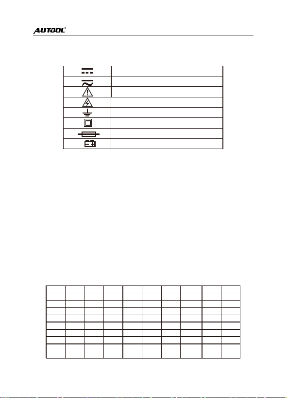
3. International Electrical Symbols
4.Specifications
Pressure Test: Gauge Pressure;
Pressure Test Unit: Kpa; Mpa; bar; inHg; PSI;
Pressure Test Range: 0 Kpa – 6000 Kpa;
Pressure Test Resolution: 1 Kpa Pressure;
Test Accuracy: +/- 0.5 %(FS) + 5dgt;
Pressure Overload Limit: 10000 Kpa(10 Mpa;100 bar);
Vacuum Test: Relative Vacuum;
Vacuum Test Unit: Kpa; Mpa; bar; inHg; PSI;
Vacuum Test Range: -101 Kpa – 0 Kpa;
Vacuum Test Resolution:1 Kpa;
Build-in 89 kinds of Refrigerant NIST :
* According to American NIST Standard
Warning
High Voltage(Electric Shock)
Earth
Double Insulation
Fuse
Battery
DC
DC/AC
R11 R113 R114 R115 R116 R12 R123 R124 R125 R1270
R13 R134A R14 R141B R142B R143A R152A R170 R21 R218
R22 R227EA R23 R236EA R245CA R245FA R290 R32 R401A R401B
R401C R402A R402B R403A R403B R404A R405A R406A R407A R407B
R407C R407D R407E R408A R409A R409B R41 R410A R410B R411A
R411B R412A R413A R414A R414B R415A R415B R416A R417A R418A
R419A R420A R421A R421B R422A R422B R422C R422D R423A R424A
R425A R426A R427A R428A R50 R500 R501 R502 R503 R504
R507A R508A R508B R509A R600 R600A R717 R744
(
CO2
)
R1234
3
Power Supply: 3 X 1.5V (SIZE.AA / LR6);
Dimension: 184 X 107 X 45.5mm / 7.3 X 4.3 X 1.8 inch ;
Weight(excludes battery): 0.446kg / 1 lb.
5. Descriptions
1- LCD Display;
2- POWER/BACKLIGHT Button: POWER BACKLIGHT (long press)(short press);
3- FUNCTION/ ZERO Button: Pressure Test Zero (long press) Test Function Switch
(short press);
4- SETTING Button: Parameter Setting (long press) Leak Test Mode:Run/Stop
(short press);
5- ARROW Button: Change Direction of Refrigerant Selection (long press)
Parameter Increment (short press);
6-Refrigerant Observation Window
7- Valve
8- 1/4inch Pressure Inlet
9- Refrigerant Inlet /Vacuum Pump Inlet
6.FUNCTION INSTRUCTIONS
6.1 Refrigerant Filling and Pressure Inspection
Pressure Test Function is used for refrigeration system repair and maintenance,
refrigerant filling and operation inspection. Build-in 89 kinds of refrigerant (NIST)
provides pressure condensation and evaporation temperature. Please read these two
types of temperature when tested pressure reading is obtained. Operation
Instructions are as follows.
4

1. Turn off the valve.
2. Press POWER Button to start the instrument. Press FUNCTION Button to select
Pressure Test Interface with Evaporation Temperature or Condensation Temperature
as below figures.
3. There will be 10 digits displayed after instru-ment turned on. Long press ZERO
button to zero reading.
4. Long press SETTING button to enter setting mode for adjusting unit and type of
refrigerant. (see 6-4 SETTING)
5. Fill refrigerant according to instructive opera-tion of refrigeration system.
6. Obtain test readings of pressure test, running test, evaporation temperature and
condensa-tion temperature.
7. Turn off valve after filling completed. Rapidly remove connection between
instrument and refrigeration system and refrigerant source.
8. Turn off the instrument.
NOTE: Filling operation of different equipment or refrigerant may vary. Please read
carefully the relevant specific operation requirements for filling operation, so as to
avoid damage to user or equipment caused by improper operation.
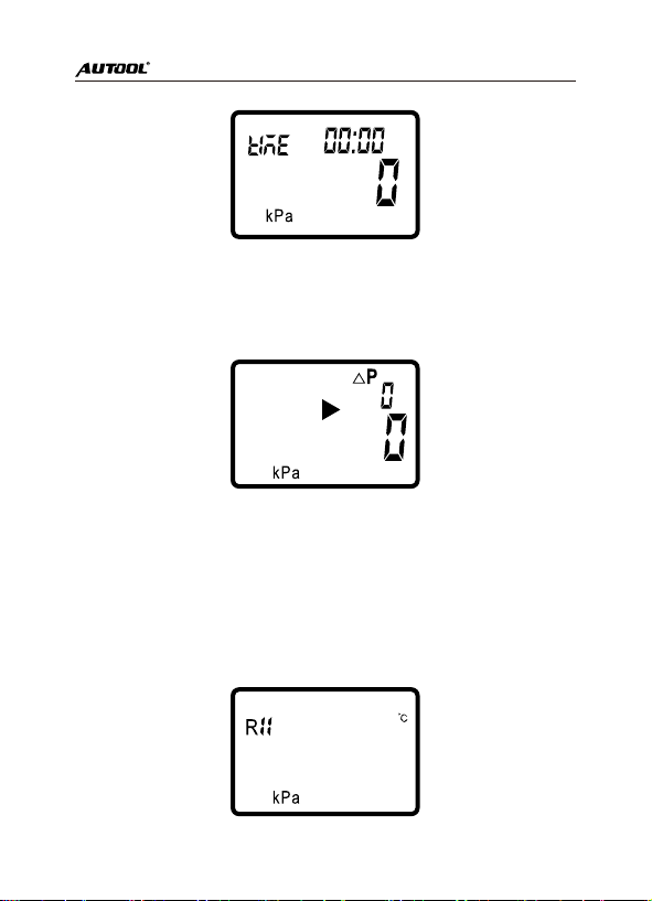
6.2. Vacuum Operation
Vacuum operation tests vacuum pressure value and calculates vacuum degree.
Operation Instructions are as follows.
1.Turn off the valve.
2.Press POWER button to start the instrument. Press FUNCTION Button to select
Vacuum Test Interface as below figures.
Pressure Test Interface with
Evaporation Temperature
Pressure Test Interface with
Condensation Temperature
5

3.Long press SETTING button to enter setting mode for adjusting unit.(see 6-4
SETTING)
4.There will be 10 digits displayed after instrument turned on. Long press ZERO
button to zero reading.
5.Operate vacuum according to instructive operation of refrigeration system.
6.Obtain test reading of vacuum pressure and vacuum degree.
7.Turn off valve and vacuum source.
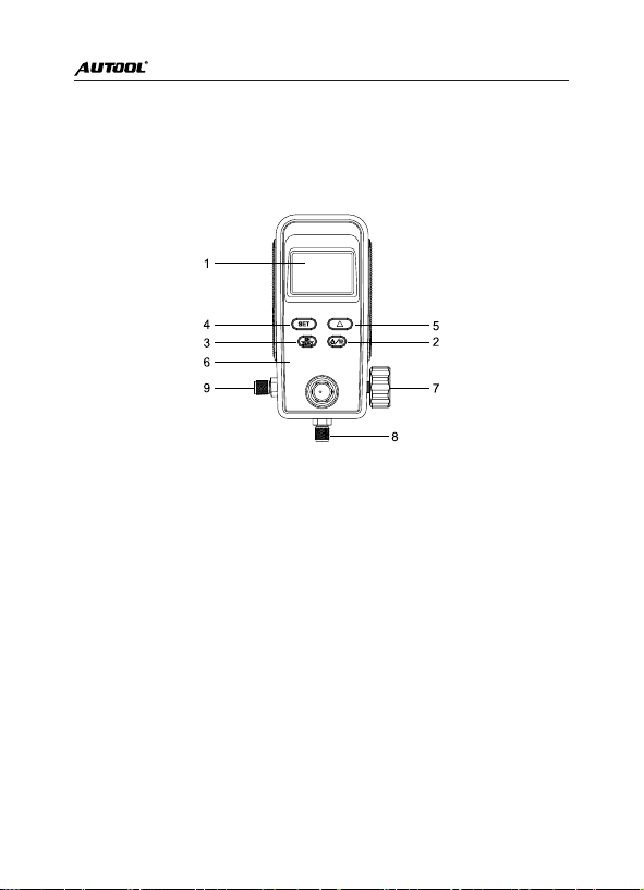
6.3. Pressure Leak Test
Pressure Leak Test is used for inspecting how much does pressure change in some
time after refrigeration system has been filled with some refrigerant or vacuumed.
1.Instrument should be turned on with valve turned off.
2.Press FUNCTION button to select Pressure Leak Test mode as below figures.
Figure with“ P”, the small number at top right corner refers to difference value of
pressure.
Figure with“STRT”, the small number at top right corner refers to original pressure.
Figure with“TIME”, the small number at top right corner refers to test time duration
with format “Hour : Minute”.
Difference Value of Pressure Original Pressure
6
3.Connect instrument to refrigeration system. Then operate vacuum or fill some
refrigerant to system. Shut the valve and start test by pressing SETTING button
when reading keeps stable. See below figure with flashing delta signal.
4.At this time instrument records original pressure and test period. Press ARROW
button could switch display to see difference value of pressure , original pressure and
test time duration respectively.
5.Press SETTING button again to stop leak test.
6.4. Setting Operation
Types of refrigerant , pressure unit and temperature unit could be changed as follow
instructions.
1.Instrument is in any test function state.
2.Long press SETTING button to display below figure.
Test Time Duration
7

3.Flashing parameter in LCD display could be changed by pressing ARROW button.
Type of refrigerant selection increment goes forward in single way, such as R1->
R2->R3 Long press ARROW button can change selection direction.
4.Short press SETTING button to switch parameter selection.
5.When all parameters are set, long press SETTING button to save selected item.
6.In case FUNCTION button is pressed accidently in the process of setting
parameters, instrument will opt out and cancel all previous set items.
7.Common Problems
7.1 Low Battery Power Supply
Instrument includes low battery indication of one battery sign at the top left corner in
LCD display. When it displays, batteries should be replaced on time to obtain
accurate test reading.
7.2 Damaged Hose or Valve Stem
Please check pipe fittings and hose before test. As long as something wrong is
visible, please replace it immediately to avoid any accidence.
7.3 Failure of Refrigerant Filling
There is a valve core in the refrigerant inlet of the system. When connecting
instrument to system, pay attention to the two terminals of the hose.
Connect one terminal with a core to the refrigera-
-tion system, while another terminal without a core to the instrument.
7.4 Potential Leak Points
Every hose terminal comes with a nylon pad with a certain service life. Please
replace it when it is overused or flawed.
Check refrigeration system’s pipes and other connectors.
8. Glossary
Saturation
The state of saturation is the coexistence of a refrigerant in a liquid and gas state.
Condensation Temperature
In the condenser, the refrigerant is condensed by the high-temperature gaseous
refrigerant to the temperature of the liquid refrigerant, that is, the saturation
temperature under condensing pressure.
Evaporation Temperature
In the evaporator, the refrigerant evaporates from the liquid refrigerant to the
temperature of the gaseous refrigerant, that is, the saturation temperature under
evaporation pressure.
Degree of Subcooling and Superheat
Subcooling: condensing temperature - condensing outlet temperature.
8

Superheat: evaporation outlet temperature- evaporation temperature.
The lower subcooling can make the refrigeration capacity of the system better.
Adding subcooling loop and economizer in the refrigeration system is to increase the
subcooling for refrigerant increasing.
The degree of expansion of the expansion valve (refrigerant charge) affects the
degree of super- heat. The greater degree of superheat, the smaller the opening of
the expansion valve can be determined( the refrigerant charge is fewer).
Sensible heat and latent heat
The amount of heat required to raise the water temperature from 0 degrees to 100
degrees is sensible heat, the water is heated to 100 degrees, and the hot water
becomes water vapor, but the temperature is still 100 degrees. The heat required for
this process is called latent heat.
Gauge pressure and absolute pressure
Gauge pressure: Refers to the pipeline pressure, or the pressure measured by
pressure gauges, vacuum gauges, U-shaped tubes, etc., also known as relative
pressure. The “table pressure” starts with atmospheric pressure and the symbol is
Pg.
Absolute pressure: The pressure directly acting on the surface of a container or
object is called “absolute pressure”, the absolute pressure value is absolute vacuum
as a starting point, the symbol is PABS (ABS is a subscript) and the absolute
pressure is atmospheric pressure + gauge pressure.
At atmospheric pressure, the gauge pressure is 0 and the absolute pressure is 1.013
bar.
Dry Bulb Temperature Wet Bulb Temperature Black Ball Temperature
Dry bulb temperature: the temperature measured by ordinary thermometers.
Wet bulb temperature: a wet cloth is wrapped around the thermometer, and the
temperature indicates a drop due to the evaporation of water. The temperature at this
time is called the wet-bulb temperature.
The device, which has both the dry ball thermometer and the wet bulb thermometer,
is called the dry humidimeter, which can be used to measure the relative humidity in
the atmosphere.
Black ball temperature: also called actual temperature, it indicates the actual sensory
temperature expressed by temperature when a person or an object is combined with
radiant heat and convective heat in a radiant heat environment.
The black ball temperature measured is generally higher than the ambient
temperature, which is the air temperature.
Relative Humidity and Absolute Humidity
Absolute humidity: the mass of water vapor in a unit volume of air is called the
"absolute humidity" of air. It is a representation of the physical quantity of
atmospheric dryness and humidity. It is usually expressed in grams of water vapor
contained in 1 cubic meter of air.
9

Relative humidity: the actual water vapor density in air and the percentage of
saturated water vapor density at the same temperature are called the “relative
humidity” of air.
The degree of dryness and humidity of the air is related to the degree of saturation of
water vapor contained in the air, but it is not directly related to the absolute amount of
water vapor contained in the air.
9. After-sale Service
Warranty
We offer repair service or replacement according to the specific type of the fault.
We guarantee that all the parts, accessories and device for replacement are brand
new.
AUTOOL will bear the shipping cost and offer the corresponding accessories for
replacement without charge if the customer sends us video and pictures of the
product that fails within 90days after receipt.
If the product has been received for more than 90 days, we will provide the spare
parts for replacement without charge but the buyer is supposed to bear the other
relevant costs.
The warranty is void if the product is
* Bought through non-official channel;
*Damaged because of improper use or maintenance not following the user manual;
Declaration
Please note that AUTOOL reserves the right to change product designs and
specifications without notice. Images or descriptions in this manual are for illustration
purposes only. Actual products may vary in terms of appearance and color. We are
always trying to offer an accurate user manual, but we can hardly guarantee that
there is absolutely no difference. The right of the final interpretation of the products
belongs to AUTOOL, and we will not be liable to any loss or damage caused by
misunderstanding.
10

Table of contents
Other AU Tool Measuring Instrument manuals

AU Tool
AU Tool BT60 User manual

AU Tool
AU Tool X50 Plus User manual

AU Tool
AU Tool SDT 206 User manual

AU Tool
AU Tool X60 User manual

AU Tool
AU Tool TW 500 User manual

AU Tool
AU Tool LM120 Plus User manual

AU Tool
AU Tool X90 User manual

AU Tool
AU Tool X90 User manual

AU Tool
AU Tool X60 User manual

AU Tool
AU Tool X91 TPMS User manual


