6789 :8;<=> ?@AB C DEF G?
HIJKLMNAJOPJ QRS T QUUQV HWXEOPYZ[J\S ]YEMJ^ _R``VabR_V_S cLd^ _R``Vae_`_ fg@Lh\ hMKEiLdJ\gNJ@XLjFkJ
Contents
1 Introduction
llllllllllllllllllllllllllllllllllllllllllllllllllllllllllllllllllllllllllllllllllllllllllllllllllllllllllllllllllllllllllllllllllll m
1.1 Intended use
llllllllllllllllllllllllllllllllllllllllllllllllllllllllllllllllllllllllllllllllllllllllllllllllllllllllllllllllllllllllllll m
1.2 Safety instructions
llllllllllllllllllllllllllllllllllllllllllllllllllllllllllllllllllllllllllllllllllllllllllllllllllllllllllllllllll n
1.3 Installation requirements
llllllllllllllllllllllllllllllllllllllllllllllllllllllllllllllllllllllllllllllllllllllllllllllllllllll n
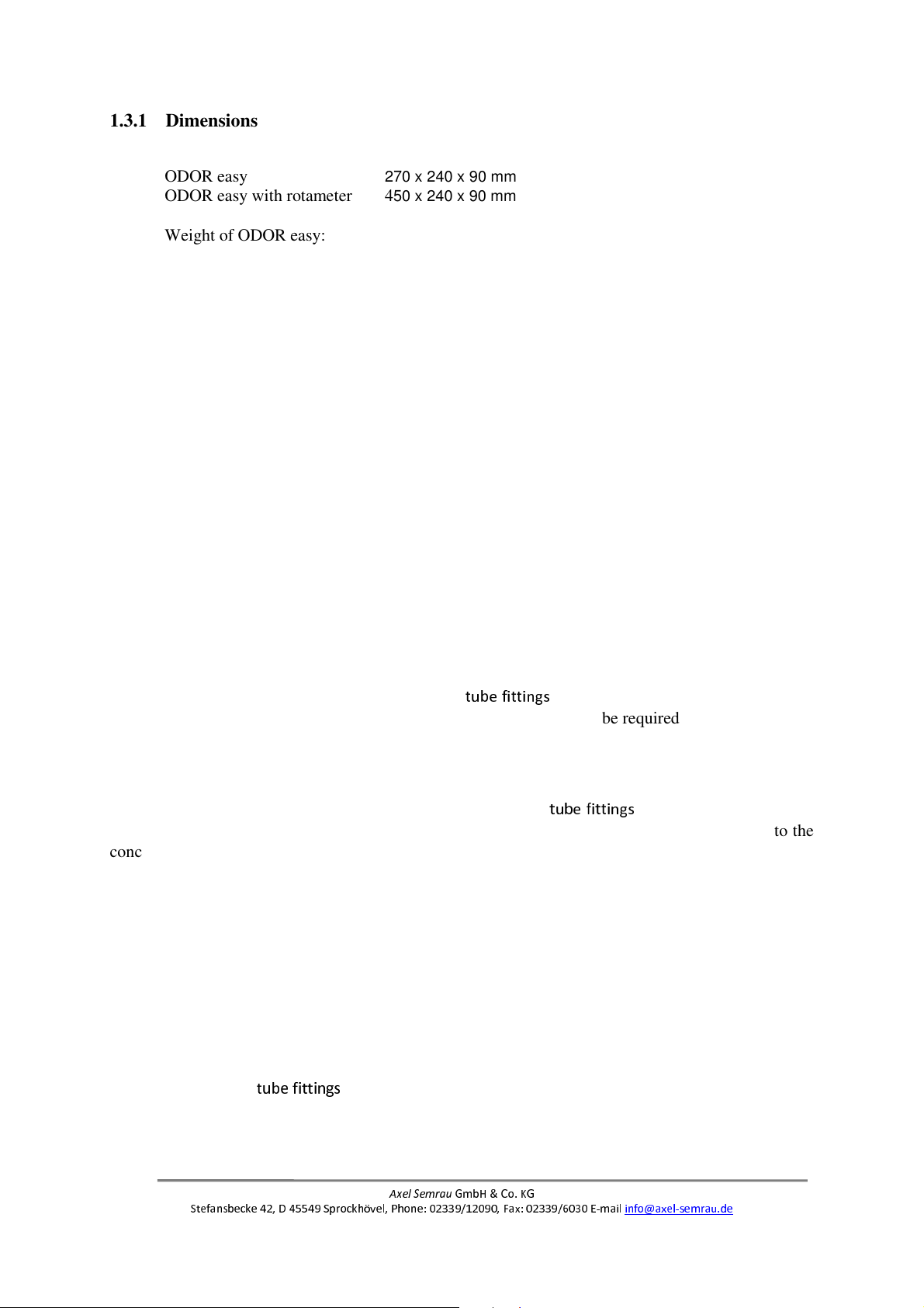
1.3.1 Dimensions
llllllllllllllllllllllllllllllllllllllllllllllllllllllllllllllllllllllllllllllllllllllllllllllllllllllllllllllllllllll o
1.3.2 Electrical connections
llllllllllllllllllllllllllllllllllllllllllllllllllllllllllllllllllllllllllllllllllllllllllllllllllll o
1.3.3 Gas connections
llllllllllllllllllllllllllllllllllllllllllllllllllllllllllllllllllllllllllllllllllllllllllllllllllllllllllllll o
1.3.4 Ambient conditions
llllllllllllllllllllllllllllllllllllllllllllllllllllllllllllllllllllllllllllllllllllllllllllllllllllllll p
1.3.5 Remote transmission
llllllllllllllllllllllllllllllllllllllllllllllllllllllllllllllllllllllllllllllllllllllllllllllllllllll p
1.3.6 Information concerning the delivery of the system
lllllllllllllllllllllllllllllllllllllllllllllllllllll p
2 Scope of delivery for ODOR EASY
llllllllllllllllllllllllllllllllllllllllllllllllllllllllllllllllllllllllllllllllllllllllllllll q
2.1 Other accessories
llllllllllllllllllllllllllllllllllllllllllllllllllllllllllllllllllllllllllllllllllllllllllllllllllllllllllllllllllll q
3 Connecting the system
lllllllllllllllllllllllllllllllllllllllllllllllllllllllllllllllllllllllllllllllllllllllllllllllllllllllllllllllll rs
3.1 Gas connections
llllllllllllllllllllllllllllllllllllllllllllllllllllllllllllllllllllllllllllllllllllllllllllllllllllllllllllllllllll rt
3.2 Electrical connections
llllllllllllllllllllllllllllllllllllllllllllllllllllllllllllllllllllllllllllllllllllllllllllllllllllllllll ru
3.2.1 Connecting the supply voltage
llllllllllllllllllllllllllllllllllllllllllllllllllllllllllllllllllllllllllllllllllll ru
3.2.2 Signal output
lllllllllllllllllllllllllllllllllllllllllllllllllllllllllllllllllllllllllllllllllllllllllllllllllllllllllllllllll ru
3.2.3 Connecting a PC/laptop/tablet to the ODOR EASY
lllllllllllllllllllllllllllllllllllllllllllllllll rm
4 Commissioning
lllllllllllllllllllllllllllllllllllllllllllllllllllllllllllllllllllllllllllllllllllllllllllllllllllllllllllllllllllllllllllll rn
4.1 Setting the gas flows
lllllllllllllllllllllllllllllllllllllllllllllllllllllllllllllllllllllllllllllllllllllllllllllllllllllllllllll rn
4.1.1 Gas connections
llllllllllllllllllllllllllllllllllllllllllllllllllllllllllllllllllllllllllllllllllllllllllllllllllllllllllll rn
4.1.2 Opening HyperTerminal
lllllllllllllllllllllllllllllllllllllllllllllllllllllllllllllllllllllllllllllllllllllllllllll rn
4.1.3 Opening the valves and setting the gas flows
lllllllllllllllllllllllllllllllllllllllllllllllllllllllllllll rv
4.2 Setting the calibration gas concentration
lllllllllllllllllllllllllllllllllllllllllllllllllllllllllllllllllllllllllll rv
4.2.1 Opening HyperTerminal
lllllllllllllllllllllllllllllllllllllllllllllllllllllllllllllllllllllllllllllllllllllllllllll rv
4.2.2 Calibration gas input
lllllllllllllllllllllllllllllllllllllllllllllllllllllllllllllllllllllllllllllllllllllllllllllllllll ro
4.3 Starting the test measurement
llllllllllllllllllllllllllllllllllllllllllllllllllllllllllllllllllllllllllllllllllllllllllll ro
4.3.1 Opening HyperTerminal
lllllllllllllllllllllllllllllllllllllllllllllllllllllllllllllllllllllllllllllllllllllllllllll ro
4.3.2 Opening the measuring menu
lllllllllllllllllllllllllllllllllllllllllllllllllllllllllllllllllllllllllllllllllllll ro
4.4 Testing the analogue output signal
lllllllllllllllllllllllllllllllllllllllllllllllllllllllllllllllllllllllllllllllllllll rp
4.4.1 Opening HyperTerminal
lllllllllllllllllllllllllllllllllllllllllllllllllllllllllllllllllllllllllllllllllllllllllllll rp
4.4.2 Opening the DAC menu
llllllllllllllllllllllllllllllllllllllllllllllllllllllllllllllllllllllllllllllllllllllllllllll rp
5 Settings
llllllllllllllllllllllllllllllllllllllllllllllllllllllllllllllllllllllllllllllllllllllllllllllllllllllllllllllllllllllllllllllllllllllllll rq
5.1 Connection parameters
llllllllllllllllllllllllllllllllllllllllllllllllllllllllllllllllllllllllllllllllllllllllllllllllllllllll rq