SMW Autoblok VNK 70-37 Operation instructions

OPEN CENTER HYDRAULIC CYLINDER Type:
CILINDRO IDRAUL. CON PASS. BARRA Tipo:
HYDRAULISCHE HOHLSPANNZYLINDER Typ:
CYLINDRE HYDR. A CENTRE OUVERT Type:
中 空 液 压 油 缸 型号:VNK
USE AND MAINTENANCE
INSTRUCTIONS Page 4
MANUALE DI
ISTRUZIONI Pag. 8
BETRIEBSANLEITUNG
Seite 12
MANUEL D’UTILISATION
Page 16
使用说明书
20 页
USE AND MAINTENANCE
INSTRUCTIONS Page 4
MANUALE DI
ISTRUZIONI Pag. 8
BETRIEBSANLEITUNG
Seite 12
MANUEL D’UTILISATION
Page 16
使用说明书
20 页
http://www.smwautoblok.com
READ CAREFULLY AND
SAVE THIS BOOKLET
LEGGERE ATTENTAMENTE E
CONSERVARE QUESTO MANUALE
HANDBUCH AUFMERKSAM
LESEN UND BEHALTEN
LIRE AVEC ATTENTION ET
GARDER CE BOUQUIN
仔细阅读
存档保存
COD. 10705105 - 05/2006
GERMANY
SMW-AUTOBLOK Spannsysteme GmbH
Postfach 1151 •D-88070 Meckenbeuren
Wiesentalstraße 28 •D-88074 Meckenbeuren
Telefon (0 75 42) 4 05-0
Vertrieb Inland:
Fax (0 75 42) 38 86
E-mail [email protected]
Sales International:
Fax (0 75 42) 4 05-1 81
E-mail [email protected]
U.S.A.
AUTOBLOK Corporation
285 Egidi Drive - Wheeling, IL 60090
Tel. 1-888-224-8254
Tel. (8 47) 2 15 - 05 91 - Fax (8 47) 2 15 - 05 94
E-mail [email protected]
Japan
SMW-AUTOBLOK Japan Inc.
1-5 Tamaike-Cho, Nishi-Ku
461-Nagoya
Tel. (0 52) 5 04 - 02 03
Fax (0 52) 5 04 - 02 05
E-mail [email protected]
Great Britain
SMW-AUTOBLOK Workholding Ltd.
8, The Metro Centre
GB-Peterborough, PE2 7UH
Tel. (0 17 33) 39 43 94 - Fax (0 17 33) 39 43 95
E-mail [email protected]
ITALY
AUTOBLOK S.p.A.
10040 Caprie - Torino
Tel 011.9 63 20 20 - Fax 011.9 63 84 56
E-mail [email protected]
France
AUTOBLOK S.A.R.L.
17, Avenue des Frères Montgolfier
Z.I. Mi Plaine - F-69680 Chassieu
Tel. 4-72 79 18 18 - Fax 4-72 79 18 19
E-mail [email protected]
Brasil
SYSTEC METALÚRGICA LTDA
R. Luiz Brisque, 980
13280-000 - Vinhedo - SP
Tel. 55 (0) 19 3886-6900 - Fax 55 (0) 19 3886-6970
E-mail [email protected]
Austria
SMW-AUTOBLOK
Salzburger Straße 257/T.33
A-4030 Linz
Tel. (07 32) 37 14 76 - Fax (07 32) 37 15 01
Mob. (0664) 3081908
E-mail [email protected]
China
SMW AUTOBLOK (Shanghai) Work Holding Co., Ltd.
Unit 6 No. 72 Jinwen Road, Zhuqiao, Nanhui,
Shanghai, 201323, P.R. China
Tel. (86) 21 58 10 63 83 - Fax. (86) 21 58 10 63 95
E-mail [email protected]
2
TYPE VNK:OPEN CENTER •VERY HIGH SPEED •SAFETY FLUID
LOCKS •COOLANT DRAIN ASSEMBLY AND PISTON
STROKE CONTROL.
TIPO VNK:PASSAGGIO BARRA •ALTISSIMA VELOCITÀ •CON
VALVOLE Di SICUREZZA •CON CARTER DI RECUPERO
REFRIGERANTE E GRUPPO CONTROLLO CORSA DEL
PISTONE.
TYP VNK:
MIT DURCHGANGSBOHRUNG
•
HÖCHSTE DREHZAHLEN
•
MIT SICHERHEITSVENTILEN
•
KÜHLMITTELAUFFANGSCHALE
UND KOLBENHUBKONTROLLE.
TYPE VNK:CENTRE OUVERT •TRES HAUTE VITESSE •VALVES
DE SECURITE •CARTER DE RECUPERATION DU
LIQUIDE D’ARROSAGE •CONTROLE DE LA COURSE
DU PISTON.
型号 VNK:中空 •高速 •安全阀 •集水盒和行程控制
TECHNICAL FEATURES: (1) Total at 30 bar and 50° C
Type 70-37 102-46 130-52 150-67 170-77 200-86 225-95 250-110 320-127
Id. No. 33094811 33094813 33094815 33094816 33094818 33094819 33094820 33094822 33094325
Piston area cm270 103 131 152 170 197 225 247 325
Max pressure bar 45 45 45 45 45 45 45 45 45
Draw-pull kN 31 46 58 68 76 88 100 110 144
Oil leakage (1) dm3/min 2.5 3 3.5 4 4.5 5 6 8 10
Max speed r.p.m. 8000 7000 6300 5500 5000 4500 4000 3600 3200
Mass Kg 8 12 15 20 23 27 30 45 61
Inertia moment Kg m20.013 0.028 0.04 0.07 0.09 0.13 0.17 0.28 0.54
CARATTERISTICHE TECNICHE: (1) Totale a 30 bar e 50° C
Tipo 70-37 102-46 130-52 150-67 170-77 200-86 225-95 250-110 320-127
Matricola 33094811 33094813 33094815 33094816 33094818 33094819 33094820 33094822 33094325
Area del pistone cm270 103 131 152 170 197 225 247 325
Pressione massima bar 45 45 45 45 45 45 45 45 45
Trazione kN 31 46 58 68 76 88 100 110 144
Drenaggio olio (1) dm3/min 2.5 3 3.5 4 4.5 5 6 8 10
Velocità max. r.p.m. 8000 7000 6300 5500 5000 4500 4000 3600 3200
Massa Kg 8 12 15 20 23 27 30 45 61
Momento di Inerzia Kg m20.013 0.028 0.04 0.07 0.09 0.13 0.17 0.28 0.54
TECHNISCHE MERKMALE: (1) Gesamt bei 30 bar und 50° C
Typ 70-37 102-46 130-52 150-67 170-77 200-86 225-95 250-110 320-127
Ident-Nr. 33094811 33094813 33094815 33094816 33094818 33094819 33094820 33094822 33094325
Kolbenfläche cm270 103 131 152 170 197 225 247 325
max. Druck bar 45 45 45 45 45 45 45 45 45
Zugkraft kN 31 46 58 68 76 88 100 110 144
Leckölmenge (1) dm3/min 2.5 3 3.5 4 4.5 5 6 8 10
max. Drehzahl r.p.m. 8000 7000 6300 5500 5000 4500 4000 3600 3200
Gewicht Kg 8 12 15 20 23 27 30 45 61
Massenträgheitsmoment Kg m20.013 0.028 0.04 0.07 0.09 0.13 0.17 0.28 0.54
CARACTERISTIQUES TECHNIQUES: (1)Total à 30 bar et 50° C.
Diamètre 70-37 102-46 130-52 150-67 170-77 200-86 225-95 250-110 320-127
Repère 33094811 33094813 33094815 33094816 33094818 33094819 33094820 33094822 33094325
Surface du piston cm270 103 131 152 170 197 225 247 325
Pression maxi bar 45 45 45 45 45 45 45 45 45
Traction kN 31 46 58 68 76 88 100 110 144
Drainage d’huile (1) dm3/min 2.5 3 3.5 4 4.5 5 6 8 110
Vitesse maxi r.p.m. 8000 7000 6300 5500 5000 4500 4000 3600 3200
Masse Kg 8 12 15 20 23 27 30 45 61
Moment d’inertie Kg m20.013 0.028 0.04 0.07 0.09 0.13 0.17 0.28 0.54
技术参数: (1)Total a 30 bar y 50° C
型号 70-37 102-46 130-52 150-67 170-77 200-86 225-95 250-110 320-127
产品编号 33094811 33094813 33094815 33094816 33094818 33094819 33094820 33094822 33094325
活塞面积 cm270 103 131 152 170 197 225 247 325
最高压力 bar 45 45 45 45 45 45 45 45 45
推-拉力 kN 31 46 58 68 76 88 100 110 144
泄油量 (1) dm3/min 2.5 3 3.5 4 4.5 5 6 8 10
最高转速 r.p.m. 8000 7000 6300 5500 5000 4500 4000 3600 3200
重量 Kg 8 12 15 20 23 27 30 45 61
转动惯量 Kg m20.013 0.028 0.04 0.07 0.09 0.13 0.17 0.28 0.54

3
VNK Type 70-37 102-46 130-52 150-67 170-77 200-86 225-95 250-110 320-127
Amm 107 130 147 163 175 190 205 220 250
B2 h6 mm 110 130 140 160 160 180 210 210 250
Cmm125 147 165 180 195 210 227 240 270
Dmmn.6 x Ø9 n.6 x Ø9 n.6 x Ø9 n.6 x Ø11 n.6 x Ø11 n.6 x Ø11 n.6 x Ø11 n.6 x Ø11 n.6 x Ø13
Emm 145 165 185 202 217 234 249 266 295
E1mm 140 162 182 197 214 228 245 266 290
F1mm M44 x 1.5 M55 x 2 M60 x 1.5 M75 x 2 M85 X 2 M95 X 2 M105 X 2 M120 X 2 M135 X 2
F2mm M42 x 1.5 M50 x 1.5 M55 x 2 M72 x 1.5 M80 x 2 M90 x 2 M100 x 2 M115 X 2 –
F3mm M42 x 1.5 M52 x 1.5 M60 x 1.5 M74 x 1.5 M84 x 1.5 M94 x 2 M104 x 2 M120 X 2 M138 x 2
Gmm50 61 70 85 95 105 115 130 145
Hmm 151 152 152 177 177 202 207 230 257
H2mm 16 16 16 21 21 21 21 26 35
Imm555888885
Kmm37.5 46.5 52.5 67.5 77 86.5 95.5 110.5 127.5
K1H9 mm 42.5 52.5 57 72.5 82 92 102.5 117.5 132
K2H9 mm 40 47 52.5 69 77 87 97 112 –
Lmm83 83 83 94 94 106 106 120 132
O inch 3/8 BSP 3/8 BSP 3/8 BSP 3/8 BSP 3/8 BSP 3/8 BSP 3/8 BSP 3/8 BSP 3/8 BSP
Pmm 67 76 78 89 94 104 112 123 133
P1mm 114 122 128 138 143 153 171 150 170
P2mm 100 100 107 127 127 127 127 162 150
R2mm 32 32 32 32 32 32 32 32 32
S max. mm 24 22 22 25 25 31 31 31 44
Tmm 67 73 73 82 82 94 94 104 113
Umm26 25 25 30 30 35 35 35 40
V1mm 9 9 9 10 10 11 11 12 14
V2mm 28 28 28 36 36 36 36 28 28
W1mm 20 25 25 25 25 32 32 32 30
W2mm 22 25 28 28 28 30 30 30 –
Xmm 5 6 6 6 6 6 6 66
amm113.5 116 116 132 132 144 149 177 196
emm128 128 144 184 184 184 184 230 230
f standard mm 65 65 80 90 90 90 90 100 100

VNK CYLINDERS USE AND MAINTENANCE INSTRUCTION
4
1. GENERAL
1.1 VNK hydraulic cylinders are the most advanced on the market as regards
speed, safety, and reliability; they have all the safety conditions required
by the Berufsgenossenschaft and by international regulations.
1.2 SAFETY VALVES. VNK cylinders have two inbuilt non-return valves
which can be inspected from the outside. They maintain the pressure in
the chambers even in the case of reduction or interruption in oil pressu-
re. (The minimum required pressure is 5 bar.)
1.3 PRESSURE RELIEF VALVES. In each VNK cylinder chamber there is a
maximum pressure valve rated to open automatically in case of over-
pressure.
1.4 PISTON STROKE CONTROL. The rear of the cylinder is equipped with
a piston stroke control system, using proximity switches (not supplied) or
using of a linear positioning system (LPS). To use this system please refer
to the specific instruction manual.
1.5 MOUNTING WITH REAR SCREWS. The VNK cylinders can be moun-
ted using rear screws (see solution 1 of fig. 2), that allow in many appli-
cations mounting of the cylinder directly onto the pulley, therefore, much
closer to the rear bearing of the spindle.
1.6 The hydraulic rotating cylinder is packed with great care prior to
despatch and is therefore safe from any damage caused by ordinary loa-
ding, transport and unloading. The external metal parts are coated with
suitable anticorrosion protection which must be removed before opera-
ting the cylinder. This is best done by a light brushing with
kerosene/paraffin, followed by the cylinder being thoroughly dried.
2. FIXING OF THE ROTATING HYDRAULIC CYLINDER TO THE LATHE
SPINDLE.
2.1 There are many different ways of mounting a rotating hydraulic cylinder
to a lathe spindle. The fixing system chosen, with or without adapter,
depends on how the rear of the spindle itself is built.
2.2
Z
In order to turn at high speed with minimum vibration, the cylinder
must be as close as possible to the rear bearing of the spindle and turn
perfectly centered in comparison to the machine's rotational axis. It is
therefore necessary before mounting the cylinder, to check that the
mating surface onto which the cylinder will bear, is running true to the fol-
lowing precision criteria:
Fig. 1
Size
Cylinder ≤170/77 ≥200/86
Concentricity A 0,01 0,015
Flatness B 0,005 0,010
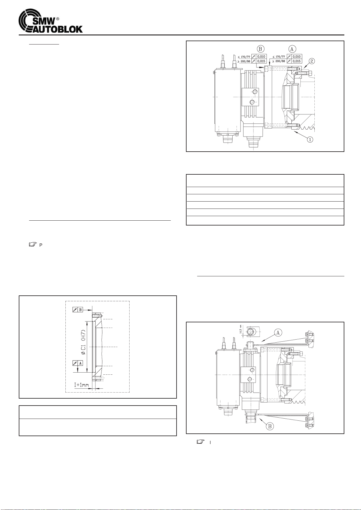
2.3 Once the precision of the adapter has been checked, assemble the
cylinder on the adaptor itself, preferably using the rear fixing screws.
.
First tighten the screws slightly, then center the cylinder so that the
rotation takes place according to the following precision criteria:
Fig. 2
Then tighten the screws fully with the torque values in the following table:
Screw nominal Class 12.9
Size F (KN) M (Nm)
M8 16 23
M10 26 45
M12 38 77
M16 72 190
M20 110 370
2.4 VNK cylinders are provided with 2 threads for connection to the draw
tube, to guarantee the best adaptation to the spinde bore. The 2 threads
are the ones marked with F1 and F2 on the drawing of page 3, and both
have a centering diameter (respectively K1 and K2). When building the
draw tube, after choosing which thread to use, provide a centering dia-
meter of 5 m in K1 or K2.
3. CYLINDER CONNECTION WITH THE DRAINING AND FEEDING
HOSES.
3.1 n all feeding and draining hoses must be flexible. Avoid using any rigid
or semirigid tube which could exercise an axial pressure on the collector
and damage the bearings.
3.2 n Only use connectors with parallel threads and a suitable seal wa-
sher. NEVER USE CONNECTORS WITH TAPERED THREADS.
Fig. 3
3.3
Z
The feeding and draining manifold (the non rotating part of the
hydraulic cylinder) must be kept in position by using a bracket anchored
on the machine (see fig. 3 , A or B). The bracket must not exert axial pres-
sure and must have a 2-3 mm radial clearance. Keep the oil draining and
the coolant draining piping vertical, in order to encourage discharge (by
gravity).
5
VNK CYLINDERS USE AND MAINTENANCE INSTRUCTION
3.4 IMPORTANT:
All hydraulic rotating cylinders with a thru hole, have labyrinth seals bet-
ween the fixed manifold and the rotating part. As the oil draining takes
place by gravity, it is necessary to have a height differential between the
draining collector and the oil level in the hydraulic unit.
In order to obtain a correct discharge of the oil and to avoid any outflow
from the labyrinths note the following instructions:
A)
Z
The drain tube must always be kept vertical.
B)
Z
The drain tube must not collapse thus reducing the cross sec-
tional area for the oil flow (there are plastic or rubber tubes which have
an inside wire frame which keeps the diameter constant).
C)
Z
The drain tubes must have a continuous slope down to the power
unit, AVOID USING SLAG SKIMMERS which could create back pressu-
re and block the tube.
D)
Z
The discharge in the power unit must take place above the oil
level, and not underneath it, to avoid backpressure
E)
Z
The power unit must have a breather which must be kept clean and
free from constriction.
4. HYDRAULIC POWER UNIT AND RECOMMENDED OILS
4.1 The unit’s tank capacity must be at least 4 times the nominal output of
the pump measured in litres/min. (eg; with a 12 l/min pump the power unit
tank must have a capacity of at least 45-50 litres). Should this be impos-
sible, we recommend using oilcooling systems. The best operating tem-
perature for hydraulic rotating cylinders is between 35° and 60°C (even
70° C will not cause any problem).
4.2 The hydraulic system must have an aspiration filter with links of 50-60 µ
and a 10 µ feeding filter (we suggest to use filter efficiency control
systems). The delivery filter must be replaced every 6-8 months.
4.3 VNK cylinders have large oil feeding holes; in order to have a good piston
speed, the feeding circuit must have the shortest pipes possible, without
constrictions and the electrovalves must have large section for the oil
flow.
4.4 RECOMMENDED OILS:
Z
The oil to be used with hydraulic rotating cylinders is specified in the
ISO 3448 type HM 32 regulation. For example:
AGIP – OSO 32
ESSO – NUTO H 32 ( o TERESSO 32 )
MOBIL DTE 24 ( o DTE LIGHT )
SHELL – TELLUS 32
n NOTE: We do not recommend using higher density oils because they
could create serious problems in the cylinder’s rotation at high speeds
and with cold oil.
Replace the oil at least every 12 – 18 months
5. PRECAUTIONS
5.1 n Before connecting the cylinder to the machine hydraulics, ensure
there is no foreign matter and metal parts circulating in the system. Link
the two feeding tubes directly and allow the oil to circulate for about 30
minutes a maximum pressure so that it is completely filtered. Then clean
the filters.
5.2 Before operating the chucking system, operated by a cylinder, carry out
the following tests:
A) n Open and close the chuck at low pressure checking that the cylin-
der moves properly without hindrance and that there are no leaks.
B) n Rotate the chuck at low speed, checking that the delivery pipes,
drain tubes or the anti rotation bracket do not hamper this movement.
C) n Bring the pressure to operating level and make another 8-10 move-
ments.
D) n Gradually increase the rotation speed and check that the feeding oil
has a minimum temperature of 35°C before attaining the max speed.
5.3 IMPORTANT
A) n Never allow the cylinder to rotate without oil pressure. This will
damage the bearings, cause seizure of the distribution ring and the body.
B) n Never rotate the cylinder at high speed with cold oil; this could
damage the bearings and the manifold ring. We recommend making a
few movements (opening/closing) at a low speed before starting.
C)
Z
VNK cylinders have a safety hole in the coolant colector which,
should the drain pipe be blocked, prevents the coolant from mixing with
the oil (C and D , pag. 24).
The operator must therefore periodically inspect the collector and
the quantity of the coolant and chips in the area.
6. ANALYSIS OF THE RISKS AND SAFETY STANDARDS.
6.1 DIRECT RISKS.
n The VNK cylinder consists of two parts: one is fixed and one rotates
at high speed. As a conse quence, there is the possibility of a seizure bet-
ween the two parts in case of non-compliance with the correct installa-
tion and maintenance instructions.
A) Installation
a1) Carefully read and follow the instructions of pos. 3 - 4 and 5 of this
manual. Special care must be given to pos. 5.1 - 5.2 and 5.3.
a2) Carefully read the trouble shooting giude, pos. 1-8.
a3) n Caution. When the cylinder is rotated for the first time, be
careful that ALL PERSONNEL STAND WELL CLEAR OF THE
CYLINDER.
B) Use e Maintenance
To avoid a seizure during the operation, carefully follow the instructions
of pos. 3-4 and 5 of this manual.
6.2 INDIRECT RISKS
Indirect risks are those that can derive from improper working or driving
of the VNK cylinder, when clamping components with power chucks or
collets.
A) n The machine must be allowed to rotate only under the
following conditions:
a1) After having checked with a pressure gauge that the feeding circuit has
reached the requested pressure.
a2) After the proximity switches (2 pcs. or more), or other systems (e.g LPS)
have confirmed the position of “component clamped”.
B) n The electric and hydraulic circuits of the machine MUST GUARAN-
TEE THAT THE COMPONENT CANNOT MOVE DURING THE SPINDLE-
ROTATION (safety against an accidental opening 1 closing of the wor-
kholding system).
C) n It is necessary to use double-solenoid valves with detented posi-
tions, TO ENSURE THAT THE POSITION IS KEPT IN THE CASE OF
LACK OF POWER (to prevent the opening of the jaws of the chuck).
D) n Inspection of the safety valves of the cylinder
After commencing to use the cylinder, it is recommended to check the
efficiency of the safety valves at intervals of 1 year.
To make this inspection it is necessary to mount 2 gauges (not supplied)
on the holes A and B (see page 24) by means of suitable fittings. Bring
the pressure to about 30 bar, alternating in the two chambers of the cylin-
der, to check that, when cutting off the feed, the pressure in the cham-
bers. does not drop below 10 bar., for at least 4 - 5 minutes.
KEY
Z
= Damage risk to the cylinder and/or chuck and/or machine.
n= Besides damage to the cylinder and the machine, RISK OF
PHYSICAL DAMAGE TO THE OPERATORS.
6
SOLUTION OF THE ABOVE PROBLEMS
Note: See also drawing at page 24.
1This is the most serious damage that can occur to the cylinder; it means
that the rotating part of the hydraulic manifold (body) is jammed in the
fixed part (manifold ring). This situation occurs when the oil in the cylin-
der is not perfectly clean or has some metallic particles or foreign parts
inside and can be caused when:
- The oil filters are insufficient or damaged
- The circuit and the hydraulic tubes are not perfectly clean.
For other possible reasons, please see pos. 2 to 6; for possible solutions,
please see pos. 7 and 8.
2Use of improper oil. An oil with too high a viscosity causes a located high
heating, when working at high speed with cold oil. It can also cause over-
heating in normal conditions.
3The cylinder has been rotated without oil pressure.
4The fittings used have conical or too long threads, that cause deforma-
tion of the manifold ring.
5The oil feeding or the oil drain tubes or the stop fork have been mounted
in such a way to apply an axial stress on the manifold ring, damaging the
bearings.
6The application requires an auxiliary device, that has been wrongly
assembled (bar holder, bar guide, component bearing), causing an axial
stress on the manifold ring, or, anomalous strains and shocks have affec-
ted the geometry of the cylinder.
7lf there is only a slight seizure, it is recommended to disassemble the
manifold ring, remove the seizure by an abrasive stone and replace the
bearings. Carefully clean before reassembling.
8lf the seizure is more serious, it becomes very difficult to dismantle and
repair the cylinder. In this case, it is recommended to send the cylinder to
one of the “Autoblok “ Service Centers, for the repair or the replacement
of the cylinder.
9Check that there is no alarm signal in the operation system of the machi-
ne that could hinder the operation of the controls. Carefully check the
electric circuit and the buttons.
10 Check the hydraulic circuit controlling the cylinder stroke is in good wor-
king condition and gives the requested pressure; check the following:
A) the oil level in the tank
B) the proper working of the pump
C) the filters must not be clogged
D) the solenoid valves must not be jammed
E) the tubes must be properly connected.
11 Be careful not to reduce the pressure to 1/3 (or less) in one move, as
regards to the starting pressure: this would prevent the working of the
safety valves, hence, the piston stroke.
It is recommended to reduce the pressure gradually, making every time a
movement of opening / closing.
12 One of the two safety valves jammed into its seat, due to different rea-
sons (dirty oil, overpressure, water hammering, changes in temperature,
wear of the internal components of the valves).
Keeping the power unit without pressure, carefully unscrew the 2 drain
screws A and B (see page 24). Be careful that one of the cylinder cham-
bers is still under pressure. By loosening these screws, a certain quantity
of oil will come out from one of them, resetting the valve control.
Reassemble and tighten the screws, then operate the cylinder. lf the
piston still does not move, it is necessary to change 1 or 2 safety valves
(see instructions).
13 Check that the draw tube for the connection to the chuck is not too long or
too short, causing a mechanical axial stop, hindering the piston stroke.
14 The oil seal between the fìxed manifold and the rotating part of the cylin-
der is made by means of labyrinth seals, that cannot be damaged. Hence
any leak in those areas can be due ONLY TO A FAULT IN THE OIL
DRAIN
Carefully read pos. 3.4 and check:
A) that the drain pipe is kept in VERTICAL position
B) that the drain pipe HAS THE SAME SECTION ON ALL ITS LENGTH.
C) that the drain pipe as a continous slope from the cylinder to the power
unit, WITHOUT MAKING AN ELBOW.
D) that the drain pipe into the power unit IS ALWAYS OVER the oil level
and NEVER below.
15 Carefully check the area where the oil comes out: if it is from the front
part, between the body (1) and the piston rod and / or from the rear, bet-
ween washer (8) and the piston rod (all the rotating parts), it is necessary
to replace the rubber seals No. (30) and (36) , see pag. 24
16 Let's suppose that the machine tool manufacturer dimensioned the
power unit considering the real needs of oil capacity. lf the power unit is
well dimensioned, there can be two kinds of problem.s:
- in the hydraulic circuit
- in the cylinder
17 Problems in the hydraulic circuit:
A) The filters are clogged and do not allow the regular flow of the pump
capacity; in this case replace them. NOTE: Be careful that the deli-
very filter must be microfibre filter with 10µ aperture size and must
be replaced every 6 - 8 months.
B) The pump is worn and does not guarantee the regular delivery.
Measure the delivery in l/min. and, if it is not enough, replace the
pump.
C)The solenoid valves do not make the whole stroke and reduce the room
for the oil flow. It can be caused by wear of the valves or by the entry
of dirty oil between the pistons.
18 Problem in the hydraulic cylinder:
To be sure that the problem is in the hydraulic circuit or in the cylinder,
mount (using 2 suitable fittings) 2 gauges in the drain holes A and B, (see
pag. 24). Check that:
a) There is pressure alternatively in one chamber of the cylinder (e.g. A =
30 bar B = 0 bar and vice versa ) .
b) That the pressure in A or B is slightly lower than the working pressure
set on the unit for the cylinder itself.
A) Wear or breakage of the main seal No. (33) of the piston (see page 24): in
This case, replace the seal.
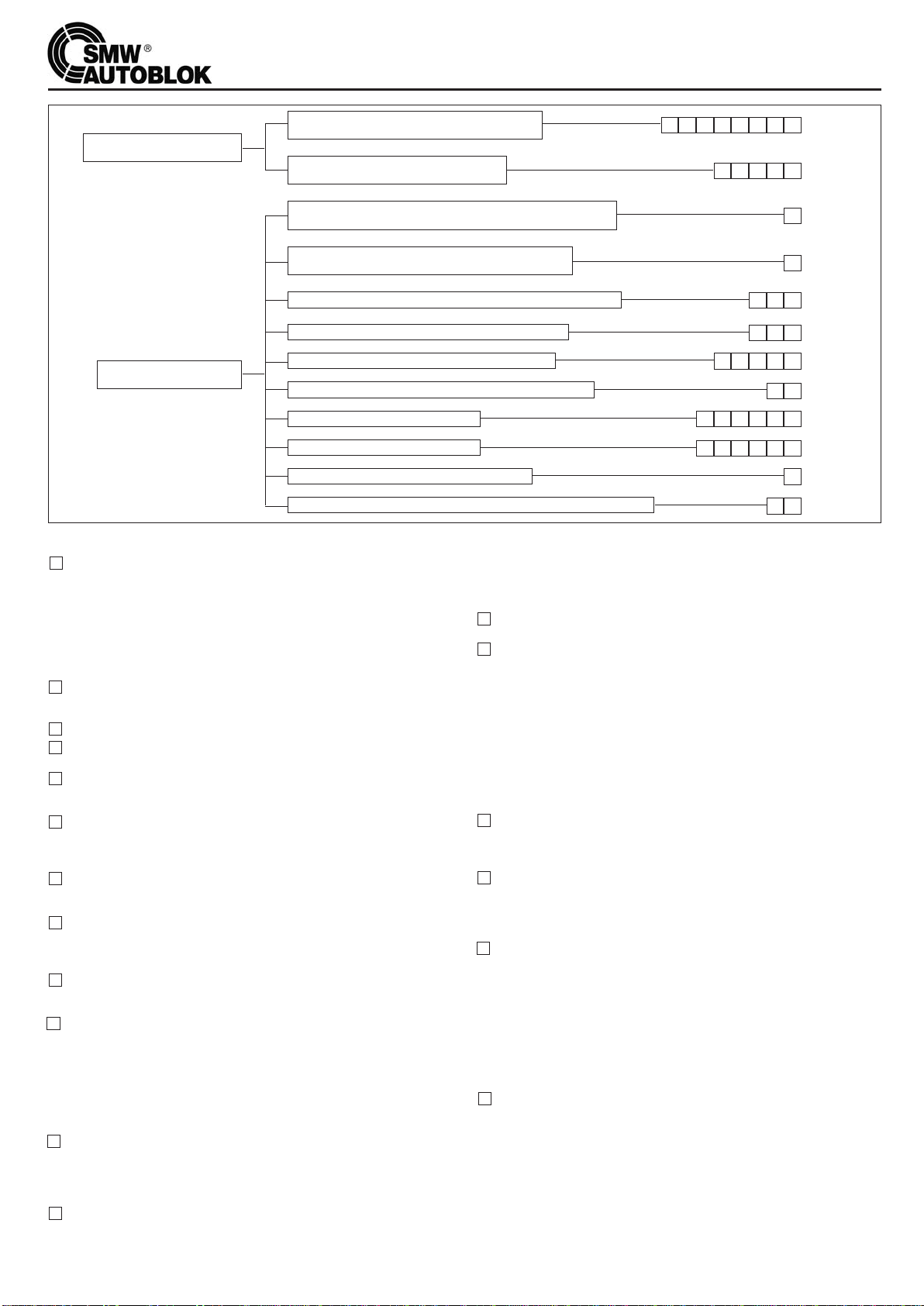
TROUBLE SHOOTING GUIDE FOR VNK CYLINDERS
The cylinder does not rotate
The cylinder works but
not properly
The rotating part is jammed
to the fixed manifold
The cylinder piston is jammed and
does not make the axial stroke
The cylinder leaks from the front and/or rear side of the
manifold ring (between the fixed and rotating part)
The cylinder leaks between the body and/or the
front cover and the piston rod (front or rear side)
The cylinder makes the axial stroke but moves too slowly
The cylinder does not make the whole axial stroke
The temperature in the cylinder has reached 70° C
There is a noise when the cylinder makes an axial stroke
The cylinder is noisy when rotation
Vibrations during rotation
The coolant leaks from the safety hole C
The coolant has entered the hydraulic circuit and the power unit
1 2 3 4 5 6 7 8
13
14
15
18
21
23
25
27
31
32
3433
30292865
266543
24
22652
2019
1716
1211109
TROUBLE SHOOTING GUIDE FOR VNK CYLINDERS
7
B) One of the pressure relief valves (20) is open, due to dirt or to the unsetting
of the springs. Try to pressurize and to relieve the pressure a few times, by
switching the power unit on and off. lf the valve still remains clogged, it is
necessary to dismantle the cylinder and replace the internal components of
the valves.
19 Usually, only a part of the cylinder stroke is used to drive a standard chuck.
To determine the length of the connection draw tube, remember that the
front limit switch is on the cylinder and the rear one on the chuck. If the draw
tube has been wrongly designed or manufactured the cylinder will not make
all the stroke requested by the chuck.
20 An unexplained reduction in the cylinder stroke (and in the stroke of the top
jaws) can be due to an accidental unscrewing of the draw tube. Screw the
draw tube properly and lock it.
21 There could be some problems in the chuck: check carefully.
22 The increase in the oil temperature is only slightly influenced by the cylinder;
it is mainly caused by the hydraulic circuit. A good power unit shoul be able
to keep the oil temperature between 35° and 65° C, even in the worst wor-
king conditions. lf the temperature is higher than 70° C, it is recommended
to increase the oil volume, by adding an auxiliary tank or by using a system
of temperature conditioning.
23 Check the oil level in the power unit: a reduction in the oil volume causes an
increase in the temperature.
24 Insufficient lubrication of the chuck can cause noises during the clamping
and unclamping of the component.
Dismantle the chuck and grease it with AUTOBLOK KO5 grease.
25 Also the partial or total breakage of the draw tube or of the threads can
cause an irregular noise: in this case, replace the damaged parts.
26 If there are vibrations when the cylinder is in thrust conditions (both when
driving a chuck or a collet), this is due to the combined bending and com-
pressive stress on the draw tube. In this case, it is recommended to insert
1 or 2 bronze bushings, to guide the draw tube onto the I.D. of the spindle.
27 When there is too much noise between the fixed manifold ring and the rota-
ting part, it is possible that the bearings are going to have a problem, due to
dirty oil or wear. Replace the bearings, check the filters and change the oil.
28 Check that the cylinder and the flange turn perfectly (see mounting
Instructions - pos. 2).
29 Check that possible shocks of bars against the cylinder hole or other vibra-
tions have not loosen the fixing screws of the cylinder in the front cover of
the cylinder. This could knock these parts off center. Check carefully and
center again.
30 Check that the draw tube is not unbalanced, off center, out of straightness
or too bent in thrust conditions.
31 Check carefully, removing the component, then the top jaws, the chuck, the
draw tube, the cylinder, the flanges, unil there are no more vibrations. Then,
balance the part removed last.
32 The coolant drain pipe is clogged by chips, preventing the coolant flowing
properly and the coolant escapes from the safety hole C.
Clean the drain pipe. To avoid a similar problem in the future, it is recom-
mended to screw the safety drain pipe on the 3/4” GAS thread of the plug
D, to be connected to the coolant tank.
33 When the coolant pipe is clogged, the volume of the coolant coming from
the thru-hole of the cylinder is higher than the drain capacity of the safety
hole C: the coolant level increases and enters the labyrinth seals of the cylin-
der. Follow the instructions of pos. 32.
34 Same problem as pos. 32, but in this case the safety hole C is obstruc-
ted: clean the hole and follow the instructions of pos. 32.
DISMANTLING AND REASSEMBLY OF VNK CYLINDER - Note: see drawing of page 24.
Dismantling
A. Operations to follow before removing the cylinder from the machine.
a1. Reduce the pressure to about 10 bar (while the piston is moving).
a2. Push the piston to about the half of its stroke.
a3. Cut off the pressure from the circuit and remove the feeding and drain pipes.
a4. By means of compressed air, alternatively blow into the feeding fittings
and collect the oil coming out from the other fitting.
a5. Push the piston fully back.
a6. Remove the rear cover (21/1) of the coolant recovery housing.
a7. Remove the stroke control disc (24) with its ring-nut (23).
a8. Remove the coolant recovery housing, unscrewing the screws (46).
lt is now possible to remove the complete unit, without influencing in any
way the adjustments of the stroke control. Be careful not to damage the
wires and the proximity switches fastened to the housing.
a9. Remove the cylinder from the machine and put it on the bench.
B. Dismanting of the piston
b1. Unscrew the two drain screws “A” and “B” and the seal below (see dra-
wing of page 24).
b2. Unscrew the fixing screws (47) of the front cover (2).
b3. Remove the front body (1) through the threaded holes.
b4. Remove the piston (3), beating with a plastic hammer on the rear side of the
piston rod. At this stage, it is possible to carry out the routine maintenance.
C. If it is necessary to replace the pressure relief valves, follow the
instructions listed below:
c1. lt is possible to place only the internal component of the valve 1 3/A”; the
housing is integral with the piston.
c2. Measure with a gauge the position of the plug of the pre-loaded spring
with regard to the edge of the housing.
c3. Unscrew the plug. (Caution: the plug is fastened with loctite)..
c4. Take out the valve and replace with new components, inserting them in
the same position as the previous ones.
c5. Screw the plug in, as deep as before, and put some loctite to fix it pro-
perly.
The positioning of the plug is very important, because it gives the pre-
load of the spring, controlling the opening of the valve.
D. lf it is necessary to replace the safety valves, with the cylinder on the
machine follow the instructions listed below.
d1. Look for the 4 holes with plugs located on the outer surface of the cylin-
der: a small one and a larger one (see sect. E-E).
d2. Remove the 4 plugs (16) e (17) (see drawing).
d3. Insert a rod into the smaller hole.
d4 Gently push the rod unit the valve comes out from the larger hole.
d5. Check the direction of the valve in the hole.
d6. Place the new valve in the same position as the previous one.
d7. Insert and screw the plugs.
E. Dismantling of the hydraulic feeding manifold: to be made only in
the case of proved damage to the bearings.
This is a very difficult operation, which should be carried out by qualified
personnel and with special equipment. If possible, send the cylinder to a
SMW-Autoblok service centre, if not, proceed as follows:
e1. Remove the cover (6).
e2. Remove support washer (8), by removing screws (43). Using an extractor
remove the oil manifold unit (5+10+11/B+12/B).
e3. Remove washer (19).
e4. Remove the front bearing (29) using a special “L” shaped tool, which has
to be put between front cover (7) and the bearing itself. There are 2 groo-
ves which should make it easier for the tool to get inside the cover.
e5. It should not be necessary to dismantle the unit 5+10+11/B+12/B.
Should it be necessary, remove screw (9) (there are 1 or 2, according to
the size) and remove ring (5) from the external housing (10) .
Reassembly
A. Reassembly of the piston (3)
a1. Insert the seals (31) – (32) – (33) and (36) in their seat, greasing them with
a suitable product.
a2. Mount the piston rod in its seat (2), beating on the draw tube end by
means of a plastic hammer.
Caution: correctly position the pressure relief valves (Their housing acts
as antirotation pins), in order to locate them in their seats in the body.
B. Reassembly of the front body (1)
b1. After greasing and mounting the seal (30) in its seat, insert the body (1)
onto flange (2) and allow the assembly of the valve housings into their
seats. Slightly screw the screws (47).
b2. Carefully center the front cover (2) as regards the body (1).
b3. Fully tighten the screws 47) and mount the plugs Aand B.
C. Reassembly of the manifold ring (5 + 10)
c1. Mount the front bearing (29) and washer (19) on the adaptor (2).
c2. Put the seals (40) in their seats, mount housing (10) on ring (5) and fix it
in position with screws (9).
c3. Mount unit (5+10) on adaptor (2). This operation requires the greatest care.
c4. Mount the seal (35) and the support washer (8) without fully tightening the
screws (43)
c5. Remount cover (6).
D. Assembly of the cylinder onto the machine
d1. Following the assembly instructions, center the cylinder body as regards
the rotation of the spindle, then, fully tighten the fixing screws.
d2. lf the manifold ring (5) - (8) has been removed, center the stop washer
“8” and tighten the screws (43).
E. Assembly of the coolant recovery housing and the piston stroke
control
e1 Mount the housing (21), fixing it by means of the screws (46), being care-
ful not to damage the wires or the proximity switches.
e2 Mount the stroke control ring (24) with its ring-nut (23).
e3. Mount the cover (21/1).
ISTRUZIONI DI USO E MANUTENZIONE DEI CILINDRI VNK
8
1. GENERALITÀ
1.1 I cilindri idraulici VNK sono quanto di più avanzato attualmente
disponibile sul mercato per quanto riguarda le caratteristiche di velocità,
sicurezza e affidabilità e dispongono di tutti i requisiti di sicurezza richie-
sti dalle norme internazionali.
1.2 VALVOLE DI SICUREZZA. I cilindri VNK hanno 2 valvole di non ritorno
incorporate e ispezionabili dall’esterno, che provvedono a mantenere la
pressione nelle camere anche in caso di riduzione o interruzione della
pressione di alimentazione dell’olio.
La pressione minima di funzionamento del cilindro prevista è 5 bar.
1.3 VALVOLE DI MASSIMA PRESSIONE. In ogni camera dei cilindri VNK è
inserita una vaIvola di massima pressione tarata per aprirsi automatica-
mente in caso di sovrapressione.
1.4 CONTROLLO CORSA DEL PISTONE. Posteriormente al cilindro, è pre-
disposto il sistema di controllo corsa del pistone a mezzo interruttori di
prossimità (non forniti), oppure a mezzo sistema LPS (Lettore lineare con-
tinuo senza contatto). Per l’utilizzo di tale dispositivo vedere le istruzioni
sul manuale specifico.
1.5 MONTAGGIO CON VITI POSTERIORI. I cilindri VNK vengono fissati
alla flangia tramite una serie di viti posteriori (vedi fig. 2). Questo permet-
te in molti casi di fissare il cilindro direttamente sulla puleggia, avvicinan-
dolo molto al cuscinetto posteriore dell’albero.
1.6 Il cilindro idraulico rotante viene fornito imballato e quindi protetto da
eventuali urti dovuti ad una normale manipolazione per carico, trasporto
e scarico; inoltre le parti metalliche esterne, soggette a rischio di ossida-
zione, sono coperte da un idoneo antiossidante protettivo. Questo
prodotto, all’atto della messa in servizio, va accuratamente asportato uti-
lizzando un pennello imbevuto di kerosene; dopo questa pulitura asciu-
gare il cilindro.
2. MONTAGGIO DEL CILINDRO SULL’ALBERO DELLA MACCHINA
2.1 Per montare il cilindro sull’albero della macchina, a seconda di come è
costruita la parte terminale dell’albero stesso, sono possibili differenti
soluzioni con o senza flangia di adattamento (vedi fig. 2).
2.2
Z
Per poter girare ad alte velocità con squilibri e vibrazioni minimi è
indispensabile che il cilindro sia il più possibile vicino al cuscinetto poste-
riore di sostegno dell’albero e giri perfettamente centrato rispetto all’as-
se di rotazione dell’albero stesso.
È pertanto indispensabile, prima di montare il cilindro, controllare che il
piano di appoggio della flangia porta-cilindro ed il diametro di centraggio
siano eseguiti correttamente e secondo i criteri di precisione descritti
nella figura 1.
Figura 1
Diametro
Cilindro≤170/77 ≥200/86
Concentricità A 0,01 0,015
Planarità B 0,005 0,010
2.3 Verificata la precisione della flangia porta-cilindro, si procede al montag-
gio del cilindro sulla flangia stessa.
Le viti di fissaggio vengono avvitate leggermente e si procede alla cen-
tratura del cilindro in modo che la rotazione avvenga secondo i criteri di
precisione descritti nella figura 2.
Figura 2
Si procede poi ad avvitare a fondo le viti con le coppie di bloccaggio riporta-
te nella seguente tabella:
Diametro nominale Classe 12.9
della vite F (KN) M (Nm)
M8 16 23
M10 26 45
M12 38 77
M16 72 190
M20 110 370
2.4 l cilindri VNK sono stati previsti con 2 filettature per il collegamento al tiran-
te di azionamento, in modo da adattarsi al meglio ai diversi diametri del
foro dell’albero macchina. Le due filettature sono quelle contrassegnate da
F1 ed F2 nel disegno di pag. 3, ed hanno entrambe un diametro di cen-
traggio (rispettivamente K1 e K2). Nella costruzione del tirante, dopo aver
scelto quale filettatura utilizzare, prevedere un centraggio sul diametro K1
o K2 della lunghezza di 5 mm.
3.
RACCORDO DEL CILINDRO CON I TUBI DI ALIMENTAZIONE E DI DRENAGGIO
3.1 n Tutti i tubi di alimentazione e scarico devono essere del tipo flessibile;
evitare qualunque tubo rigido o semirigido che potrebbe esercitare
una spinta assiale sul collettore e danneggiare i cuscinetti.
3.2 n Utilizzare unicamente raccordi e tubi con filettatura cilindrica con la
relativa rosetta di tenuta. MAI UTILIZZARE RACCORDI O TUBI CON
FILETTATURA CONICA.
Figura 3
3.3
Z
Il collettore di alimentazione e di drenaggio (parte non rotante del
cilindro) va mantenuto in posizione a mezzo di una forcella ancorata alla
macchina come presentato in figura 3 (soluzione A oppure B).
Tale forcella deve avere un’asola di guida che si impegna preferibilmente
sul raccordo di drenaggio dell’olio oppure su un perno rivestito in gomma
e fissato nella parte superiore del collettore. La forcella non deve eserci-
tare spinte assiali e deve avere 2-3 mm. di gioco radiale; essa mantiene
i raccordi di drenaggio dell’olio e del refrigerante verticali in modo da faci-
litarne il deflusso per gravità.

ISTRUZIONI DI USO E MANUTENZIONE DEI CILINDRI VNK
9
3.4 IMPORTANTE:
Su tutti i cilindri idraulici rotanti con passaggio barra, tra la parte fissa
(anello di distribuzione dell’olio) e la parte rotante, le tenute radiali sono
fatte a mezzo di guarnizioni meccaniche a labirinto.
Poiché il drenaggio dell’olio avviene normalmente per gravità, è neces-
sario un certo dislivello di altezza tra il raccordo di scarico ed il livello del-
l’olio nella centrale idraulica.
Per ottenere una corretta evacuazione dell’olio ed evitare fuoriuscite dai
labirinti è necessario seguire le seguenti indicazioni:
A)
Z
Il raccordo di drenaggio dell’olio deve essere mantenuto sem-
pre in posizione verticale.
B)
Z
Il tubo di drenaggio non deve avere restringimenti di sezione,
deve essere flessibile ma non si deve afflosciare con il calore, riducendo
la sezione di passaggio dell’olio (si consigliano tubi in gomma plastica
con l’anima interna a spirale che ne mantiene costante la sezione).
C)
Z
Il tubo di drenaggio deve avere una pendenza continua fino alla
centralina; EVITARE ASSOLUTAMENTE DEI SIFONI che creerebbero
possibili contropressioni e ingorgamento del tubo.
D)
Z
Lo scarico nella centrale idraulica deve avvenire sempre SOPRA
il livello dell’olio e MAI sotto per evitare possibili contropressioni.
E)
Z
Il tappo della centrale idraulica non deve essere ermetico ma
deve essere provvisto di uno sfiato che deve essere mantenuto libero
e pulito.
4. CENTRALE IDRAULICA DI COMANDO E OLII CONSIGLIATI
4.1 Il serbatoio della centrale idraulica dovrebbe essere almeno 4 volte la
portata della pompa in I/min. (ad esempio con una portata della pompa
di 12 I/min. è necessario un serbatoio di 45-50 litri) onde evitare un
eccessivo riscaldamento dell’olio; qualora ciò non fosse possibile si con-
siglia di utilizzare sistemi di refrigerazione dell’olio.
La temperatura ottimale per il buon funzionamento del cilindro idraulico
è compresa tra i 35° e i 60°C (i 70°C possono comunque essere raggiunti
senza problemi); è quindi consigliabile strutturare la centrale idraulica per
ottenere questi risultati anche nelle condizioni di utilizzo della macchina
più gravose.
4.2 Il sistema idraulico deve essere provvisto di un filtro in aspirazione con
maglie di 50-60 micron e di un filtro di mandata di 10 micron (si consi-
gliano sistemi di controllo dell’efficienza dei filtri).
Prevedere la sostituzione del filtro di mandata ogni 6-8 mesi.
4.3 I cilindri VNK hanno dei grandi fori di alimentazione dell’olio; per ottene-
re una buona velocità di spostamento del pistone è comunque necessa-
rio che il circuito di alimentazione abbia i tubi più corti possibile, evitan-
do strozzature e prevedendo elettrovalvole con grande sezione di pas-
saggio dell’olio.
4.4 OLII CONSIGLIATI:
Z
L’olio più idoneo ad essere usato per l’azionamento di cilindri idrau-
lici rotanti è identificato alla norma ISO 3448 con il tipo HM 32.
Ad esempio, citiamo alcuni tra quelli commercialmente più comuni.
AGIP – OSO 32
ESSO – NUTO H 32 ( o TERESSO 32 )
MOBIL DTE 24 ( o DTE LIGHT )
SHELL – TELLUS 32
n Nota: Si sconsiglia l’utilizzo di olii con viscosità superiori poiché
potrebbero creare seri problemi nella rotazione del cilindro agli alti regimi
con olio freddo.
Prevedere la sostituzione dell’olio ogni 12-18 mesi massimo.
5. PRECAUZIONI
5.1 n Prima di collegare il cilindro all’impianto idraulico occorre assicu-
rarsi che non ci siano particelle metalliche o corpi estranei nel circuito di
alimentazione; pulire accuratamente i raccordi e l’interno dei tubi soffian-
do con aria compressa.
È INDISPENSABILE, per assicurarsi che il circuito sia pulito collegare i 2
tubi di alimentazione direttamente tra loro e fare circolare l’olio per circa
30 minuti al massimo della pressione così che il fluido venga accurata-
mente filtrato.
Pulire i filtri dopo questa operazione.
5.2 Prima della messa in funzione definitiva del gruppo mandrino - cilindro
si consigliano alcune semplici operazioni:
A) n Con cilindro non in rotazione, fare alcuni movimenti di apertura e
chiusura a bassa pressione verificando che non vi siano nè impedimenti
al movimento del cilindro nè eventuali perdite.
B) n Far ruotare il mandrino a bassa velocità per circa 15 minuti verifi-
cando che i tubi di mandata e drenaggio o la forcella antirotazione non
costituiscano alcun impedimento alla rotazione.
C) n Portare la pressione a regime ed eseguire ancora 8-10 movimenti di
apertura e chiusura.
D) n Aumentare gradatamente la velocità di rotazione verificando che l’o-
lio di alimentazione abbia una temperatura minima di 35°C prima di
raggiungere la velocità massima.
5.3 IMPORTANTE
A) n Mai far ruotare il cilindro senza pressione di olio. Questo cause-
rebbe il danneggiamento dei cuscinetti ed il grippaggio dell’anello di dis-
tribuzione e del corpo.
B) n Non azionare il cilindro ad elevate velocità di rotazione con olio
freddo; questo potrebbe danneggiare i cuscinetti e l’anello di distribu-
zione.
Si consiglia, all’inizio del lavoro, di effettuare alcuni movimenti di apertu-
ra e chiusura con basse velocità di rotazione.
C)
Z
I cilindri VNK hanno sulla cuffia di recupero del refrigerante un foro
di sicurezza per evitare che, in caso di intasamento del tubo di scarico, il
refrigerante si mescoli all’olio (C e D vedi pag. 24).
L’operatore dovrà controllare periodicamente che non si verifichino
intasamenti di trucioli nel tubo di scarico del refrigerante.
6. ANALISI DEI RISCHI E NORME DI SICUREZZA
6.1 RISCHI DIRETTI
n Essendo i cilindri idraulici VNK costituiti da 2 parti di cui una fissa ed
una rotante ad alta velocità, esiste la possibilità di un grippaggio tra le 2
parti se non vengono osservate le corrette istruzioni di installazione uso
e manutenzione.
A) Installazione
a1) Leggere attentamente e seguire le indicazioni dei punti 3-4 e 5 di questo
manuale (in modo particolare i punti 5.1 - 5.2 e 5.3).
a2) Leggere attentamente le possibili cause di grippaggio riportate nella
“guida alla soluzione dei problemi” ai punti 1 - 8.
a3) n In particolare, durante la prima messa in rotazione del clilindro
NESSUN OPERATORE DEVE TROVARSI IN PROSSIMITA’ DEL CILIN-
DRO STESSO.
B) Uso e Manutenzione
Per evitare grippaggi durante la lavorazione, attenersi alle indicazioni dei
punti 3-4 e 5 del presente manuale.
6.2 RISCHI INDIRETTI
Si considerano rischi indiretti quelli che possono derivare nel bloccaggio
dei pezzi su autocentranti o porta-pinze in conseguenza di un cattivo fun-
zionamento o errato azionamento dei cilindri VNK.
A) n La Macchina deve essere abilitata alla rotazione solo dopo:
a1) Il controllo a mezzo di un pressostato del raggiungimento nel circuito di
alimentazione della pressione pre-fissata.
a2) Il controllo a mezzo di 2 o più interruttori di prossimità o di altri dispositi-
vi della posizione di pezzo bloccato.
B) n I circuiti elettrici ed idraulici della macchina devono essere confìgu-
rati in modo da ESCLUDERE LA POSSIBILITA’ DI APERTURA E CHIU-
SURA DEL PEZZO DURANTE LA ROTAZIONE DELL’ALBERO.
C) n È necessario utilizzare elettrovalvole con doppio solenoide a posi-
zioni fisse in modo che, in MANCANZA DI CORRENTE LA POSIZIONE
VENGA MANTENUTA E NON SI VERIFICHI L’APERTURA DELLE GRIFFE
DELL’AUTOCENTRANTE
D) n Controllo delle valvole di sicurezza del cilindro
Ad intervalli di 1 anno della messa in funzione del cilindro si consiglia la
verifica dell’efficienza delle valvole di sicurezza.
Per questa operazione è necessario montare sui fori A e B (vedi pag. 24)
a mezzo di appositi raccordi, 2 manometri (non forniti). Mandare la pres-
sione a circa 30 bar, alternativamente nelle 2 camere del cilindro e verifi-
care che, togliendo l’alimentazione, la pressione nelle camere rimanga
sopra i 10 bar per almeno 4-5 minuti
LEGENDA
Z
= Rischio di danneggiamento al cilindro e/o al mandrino e/o alla mac-
china.
n=Oltre al danneggiamento del cilindro e del macchinario, RISCHIO
FISICO PER GLI OPERATORI.

10
SOLUZIONE DEI PROBLEMI SOPRA RIPORTATI
Nota: Fare riferimento anche al disegno di pagina 24.
1Probabilmente la parte rotante (corpo) della distribuzione idraulica è grippata
sulla parte fissa (anello di distribuzione): questo è il danno peggiore che possa
avvenire sul cilindro. Uno dei motivi può essere l’utilizzo di olio sporco con par-
ticelle metalliche e corpi estranei in sospensione dovuto a:
- Insufficienza o danneggiamento dei filtri dell’olio
- Circuito e tubi idraulici non accuratamente puliti
Altri motivi possono essere ricercati nei punti seguenti dal n° 2 al n° 6.
I rimedi a questo problema sono suggeriti nei punti 7e 8.
2Olio non adatto; una viscosità troppo elevata provoca un riscaldamento loca-
le elevatissimo con olio freddo e provoca un maggiore riscaldamento anche
a regime.
3Il cilindro è stato messo in rotazione senza la pressione dell’olio.
4Sono stati utilizzati raccordi con filettature coniche o troppo lunghe che hanno
provocato la deformazione dell’anello di distribuzione.
5I tubi di alimentazione o di scarico dell’olio o la forcella di arresto rotazione sono
stati montati in modo da applicare uno sforzo assiale sull’anello di distribuzione
provocando il danneggiamento dei cuscinetti.
6Sono stati applicati dispositivi ausiliari in modo errato (fermo barra, guida barra,
appoggio pezzo) che hanno applicato un sforzo assiale sull’anello di distribuzio-
ne o sollecitazioni e urti anomali che hanno alterato la geometria del cilindro.
7Se la grippatura è di lieve entità si consiglia di smontare l’anello di distribuzione,
togliere con una pietra abrasiva le eventuali piccole grippature e sostituire i cusci-
netti. Lavare accuratamente prima del rimontaggio.
8Se la grippatura è di grande entità lo smontaggio e la riparazione diventano molto
difficoltose, si consiglia di inviare il cilindro a uno dei centri di servizio “AUTO-
BLOK” per la riparazione o di sostituire il cilindro.
9Verificare che non vi siano allarmi nel sistema operazionale della macchina che
possano inibire il funzionamento dei comandi; in particolare verificare il circuito
elettrico ed i pulsanti.
10 Verificare che il circuito idraulico che comanda il movimento del cilindro sia effi-
ciente e fornisca la pressione necessaria; controllare:
A) il livello dell’olio nel serbatoio
B) che la pompa funzioni regolarmente
C) che i filtri non siano intasati
D) che le elettrovalvole non siano bloccate
E) che i tubi siano collegati correttamente
11 Assicurarsi di non aver ridotto la pressione in una sola manovra a 1/3 (o meno)
della pressione precedentemente impostata; questo provoca l’impossibilità di
pilotare le valvole di sicurezza e quindi di comandare il movimento del pistone. Si
consiglia di ridurre la pressione gradualmente con più manovre operando una
apertura/chiusura ogni volta.
12 Per vari motivi (olio sporco, sovrapressioni, colpi d’ariete, variazioni di tempera-
tura, usura dei componenti interni delle valvole) una delle 2 valvole di sicurezza si
è bloccata nella sua sede. Per sbloccarla, operare come segue: con centralina
non in pressione, svitare con molta attenzione (una delle camere del cilindro è
ancora pressurizzata) le 2 viti di spurgo A e B (vedi pag. 24)
Allentando queste viti, una di esse “sfiaterà” un certo volume d’olio e si potrà così
tornare a pilotare la valvola. Rimontare quindi le viti e mettere in funzione il cilin-
dro. Se anche così il pistone non si muove è necessario cambiare 1 o 2 valvole
di sicurezza (vedi istruzioni).
13 Verificare che il tirante di raccordo con l’autocentrante non sia troppo lungo
(o corto) e provochi degli arresti assiali meccanici che impediscono la corsa del
pistone.
14 Tra l’anello di distribuzione fisso e la parte rotante del cilindro, la tenuta dell’olio è
fatta tramite guarnizioni meccaniche a labirinto che non possono essere danneg-
giate; dunque OGNI EVENTUALE PERDITA IN QUESTE ZONE È DOVUTA
UNICAMENTE AD UN DIFETTO DI DRENAGGIO DELL’OLIO.
Leggere con attenzione il punto 3.4 ed in particolare verificare:
A) Che il raccordo di drenaggio sia mantenuto in posizione VERTICALE.
B) Che il tubo di drenaggio NON ABBIA RESTRINGIMENTI DI SEZIONE.
C) Che il tubo di drenaggio abbia una pendenza continua dal cilindro alla centralina
SENZA SIFONI
D) Che lo scarico del tubo nella centralina sia SEMPRE SOPRA il livello dell’olio e
MAI sotto.
15 Controllare con attenzione il punto di fuoriuscita dell’olio; se questo fuoriesce
anteriormente tra il corpo (1) e lo stelo stantuffo e/o posteriomente tra la rondella
(8) lo stelo stantuffo (tutte parti rotanti) è necessario sostituire le guarnizioni in
gomma (30 e 36) (vedi elenco dei ricambi a pag. 24).
16 Si presuppone che il costruttore della macchina abbia dimensionato la centrale
idraulica tenendo conto delle necessità di portata effettiva dell’olio. Se la centra-
le è ben dimensionata ci possono essere 2 tipi di inconvenienti:
- Problemi nell’impianto idraulico
- Problemi sul cilindro
17 Problemi nell’impianto idraulico:
A) I filtri sono intasati per cui non permettono il passaggio regolare della portata della
pompa. È necessario sostituire i filtri. N.B. Si ricorda che il filtro in mandata
da 10 micron è generalmente in microfibra e deve essere sostituito ogni
6-8 mesi.
B) La pompa è usurata per cui non fornisce più la portata iniziale. Occorre misurare
la portata in I/min. e se insufficiente sostituire la pompa.
C) Le elettrovalvole, a causa di usura o di sporcizia tra i pistoncini non fanno tutta la
corsa e riducono la sezione di passaggio dell’olio.
18 Problemi sul cilindro idraulico.
Per determinare con certezza se si tratta di un problema dell’impianto idraulico o
del cilindro si consiglia di montare (tramite 2 appositi raccordi) 2 manometri sui
fori A e B (vedi pag. 24) e controllare che:
Ci sia pressione alternativamente in una sola camera del cilindro (es. A = 30 bar
B = 0 bar e viceversa).
La pressione in A o B sia solo di poco inferiore alla pressione di esercizio impo-
stata sulla centralina per il cilindro stesso.
I problemi sul cilindro possono essere:
A) Usura o rottura della guarnizione principale del pistone (33) in questo caso la
guarnizione va sostituita.
B) Una valvola di massima pressione (20) è aperta per introduzione di sporco o sta-
ratura delle molle. Si consiglia di mettere e togliere pressione parecchie volte
accendendo e spegnendo la centralina e provando così a disinceppare la valvo-
la; se non è sufficiente bisogna smontare il cilindro e sostituire le parti interne della
valvola.
19 Normalmente per l’azionamento di autocentranti standard si utilizza solo una
parte della corsa totale del cilindro. Nella determinazione della lunghezza del
tirante di unione tra cilindro e mandrino si prevede il fine corsa anteriore sul cilin-
dro e quello posteriore sull’autocentrante.
Evidentemente se il tirante è stato disegnato o realizzato in modo errato il cilindro
non farà tutta la corsa necessaria al mandrino.
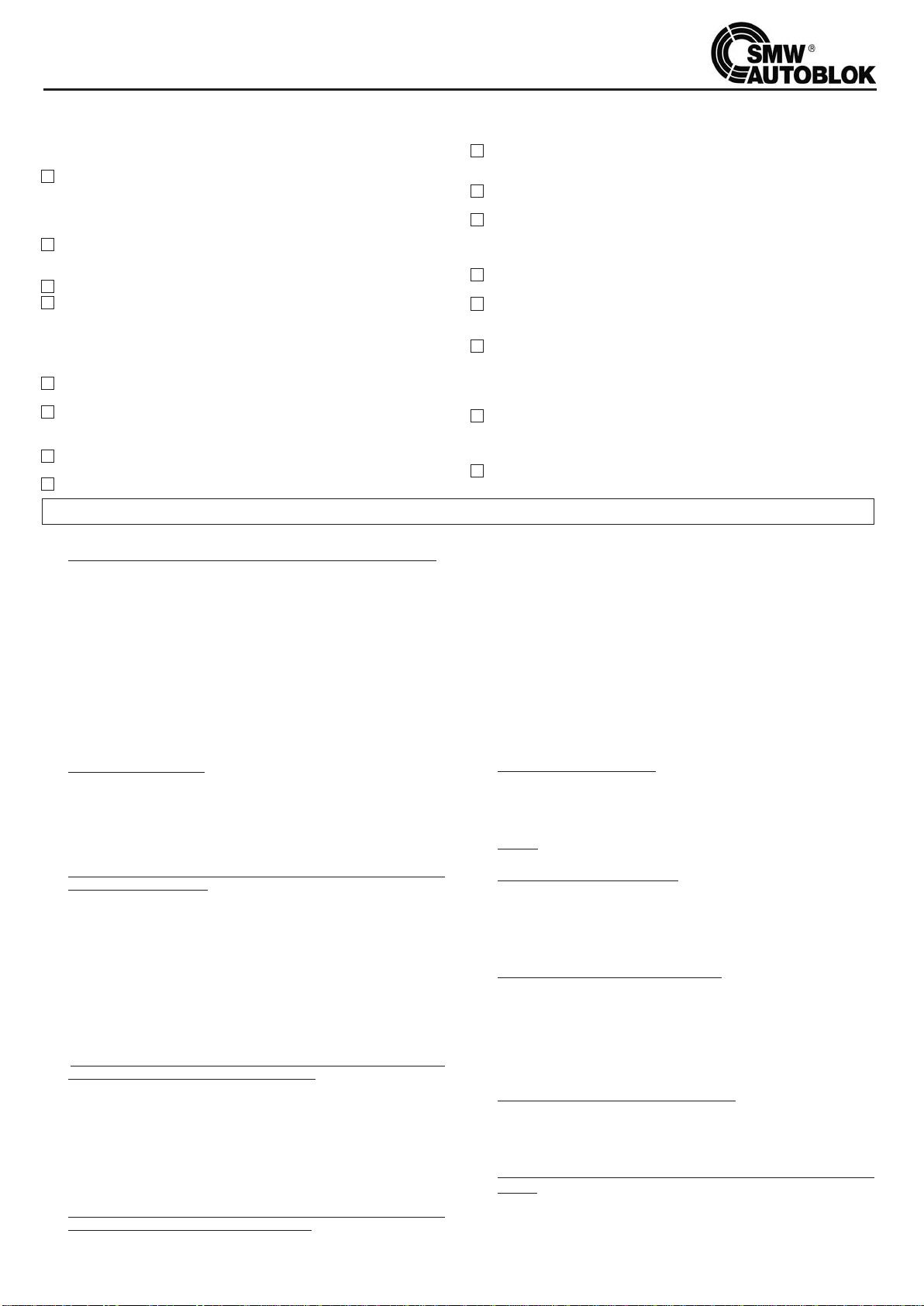
GUIDA ALLA SOLUZIONE DEI PROBLEMI SUI CILINDRI VNK
Il cilindro non funziona
Il cilindro non funziona
correttamente
Il cilindro non gira; la parte rotante è bloccata
rispetto all’anello di distribuzione fisso
Il pistone del cilindro è bloccato e
non fa la corsa assiale
Il cilindro perde olio dai lati anteriori e/o posteriori dell’anello di
distribuzione (anteriormente o posteriormente)
Il cilindro perde olio tra il corpo, la flangia e lo stelo
stantuffo (anteriormente o posteriormente)
Il cilindro fa la corsa assiale ma si muove molto lentamente
Il cilindro non fa completamente la corsa assiale
La temperatura del cilindro è elevata (più di 70° C)
Rumorosità durante la corsa assiale del pistone
Rumorosità durante la rotazione
Vibrazioni durante la rotazione
Il liquido refrigerante fuoriesce dal foro di sicurezza C
Il liquido refrigerante è entrato nel circuito idraulico e nella centralina
1 2 3 4 5 6 7 8
13
14
15
18
21
23
25
27
31
32
3433
30292865
266543
24
22652
2019
1716
1211109

GUIDA ALLA SOLUZIONE DEI PROBLEMI SUI CILINDRI VNK
11
20 Una riduzione anomala della corsa del cilindro (e della corsa dei morsetti) può
essere dovuta allo svitamento accidentale del tirante. Riavvitarlo correttamente e
bloccarne lo svitamento.
21 Ci possono essere rotture o anomalie sull’autocentrante: verificare.
22 L’innalzamento della temperatura dell’olio è dovuta solo in minima parte al cilin-
dro mentre, in maggior parte, è dovuta all’impianto idraulico. Una centrale idrau-
lica adeguatamente strutturata dovrebbe poter mantenere la temperatura dell’o-
lio in condizioni di utilizzo gravose tra i 35° e 60° C che è la temperatura ottima-
le di utilizzo dei cilindri.
Se la temperatura è superiore ai 70°C, e consigliabile aumentare il volume dell’o-
lio collegando un serbatoio supplementare o utilizzare un sistema di condiziona-
mento della temperatura.
23 Verificare il livello dell’olio nella centrale; una diminuzione del volume di olio pro-
voca un’innalzamento della temperatura.
24 Un’insufficiente lubrificazione dell’autocentrante può provocare dei rumori spe-
cialmente nel bloccaggio e sbloccaggio del pezzo.
Smontare, pulire e ingrassare l’autocentrante con grasso AUTOBLOK KO5.
25
La parziale o totale rottura del tirante o delle filettature di unione può provocare rumori
anomali. Verificare immediatamente e, se necessario, sostituire le parti danneggiate.
26 Quando, usando il cilindro in trazione, non vi sono vibrazioni ma ve ne sono quan-
do il cilindro è in spinta, sia nell’azionamento di autocentranti che di pinze, que-
sto è dovuto alla flessione che si verifica sul tirante in conseguenza del carico di
punta. In questo caso è necessario riportare sul tirante 1 o 2 anelli di bronzo che
guidino il tirante stesso sul diametro interno dell’albero.
27 Quando aumenta molto la rumorosità tra l’anello di distribuzione fisso e la parte
rotante è possibile che stiano sorgendo problemi sui cuscinetti a causa di impu-
rità nell’olio o per usura. Si consiglia di sostituire i cuscinetti, verificare i filtri e
cambiare l’olio.
28 Verificare che il cilindro e la flangia di attacco girino ben centrati (vedi le istruzio-
ni di montaggio al punto 2).
29 Verificare che eventuali sbattimenti delle barre nel foro del cilindro o altre vibra-
zioni non abbiano allentato le viti di fissaggio del cilindro alla flangia di attacco e/o
le viti di fissaggio del corpo alla flangia anteriore del cilindro stesso, determinan-
do la scentratura dei vari elementi. Ricentrare il tutto.
30 Verificare che il tirante non sia sbilanciato, scentrato, fuori rettilinearità o si incur-
vi eccessivamente in spinta.
31 Ricercare l’elemento di squilibrio iniziando a togliere il pezzo, i morsetti, l’auto-
centrante, il tirante, il cilindro, le flange fino all’eliminazione della vibrazione, quin-
di bilanciare l’ultimo elemento smontato.
32 ll tubo di scarico del liquido refrigerante è ostruito dall’accumularsi dei trucioli per
cui il refrigerante stesso non riesce a defluire normalmente e fuoriesce dal foro di
sicurezza C.
Ènecessario pulire il tubo di scarico. Si consiglia, per evitare questo problema in
futuro, di collegare al filetto 3/8 GAS del tappo D un tubo di drenaggio di sicu-
rezza da raccordare al serbatoio del refrigerante.
33 Il tubo di scarico del liquido refrigerante è ostruito dall’accumularsi dei trucioli per
cui il refrigerante stesso non riesce a defluire normalmente.
Essendo la quantità di refrigerante in arrivo dal passaggio barra del cilindro mag-
giore della capacità di scarico del foro di sicurezza C, il livello del liquido aumen-
ta fino a penetrare attraverso le guarnizioni meccaniche a labirinto nell’olio del
cilindro. Procedere come al punto 32.
34
Il problema è lo stesso del punto 32 con la differenza che il foro di sicurezza C è stato
chiuso. Togliere l’ostruzione al foro di sicurezza C o procedere come al punto 32.
SMONTAGGIO E RIMONTAGGIO DEL CILINDRO VNK - Nota: fare riferimento al disegno di pag. 24 .
Smontaggio
A. Operazioni da eseguire prima di togliere il cilindro dalla macchina.
a1. Abbassare la pressione (con lo stantuffo in movimento) a circa 10 bar
a2. Portare lo stantuffo ad un punto intermedio della corsa.
a3. Togliere la pressione dal circuito e smontare i tubi di alimentazione e drenaggio.
a4. Con una pistola ad aria compressa soffiare alternativamente nei raccordi di ali-
mentazione, avendo cura di raccogliere in un recipiente l’olio che fuoriesce dal-
l’altro raccordo.
a5. Portare lo stantuffo nella posizione tutto indietro
a6. Smontare il coperchio posteriore (21/1) della cuffia recupero refrigerante.
a7. Smontare il disco di controllo corsa (24) con la rispettiva ghiera di bloccaggio (23).
a8. Smontare la cuffia recupero refrigerante togliendo le viti (46).
Questa operazione permette di smontare il gruppo senza alterare le regolazioni
del controllo corsa; pertanto prestare attenzione a non danneggiare i fili ed i pro-
ximity fissati alla cuffia stessa.
a9. Smontare il cilindro della macchina e metterlo sul banco.
B. Smontaggio dello stantuffo
b1. Svitare le due viti di spurgo, indicate sul corpo cilindro e sul disegno a pag. 24
con “A” e “B” e togliere la guarnizione sottostante.
b2. Svitare le viti (47) di bloccaggio della flangia (2).
b3. Smontare il corpo anteriore (1) utilizzando i fori filettati per estrazione.
b4. Estrarre lo stantuffo (3) battendo con un martello di plastica sulla parte posterio-
re dello stelo.
Lo smontaggio, per eseguire una manutenzione ordinaria, è a questo punto
completato.
C. In caso sia necessario sostituire le valvole di massima pressione procedere
nel modo seguente:
c1. Delle valvole di massima pressione (20) è possibile sostituire la sola parte intema,
l’involucro è praticamente solidale allo stantuffo.
c2. Misurare con un calibro la posizione del tappo di precarico molla rispetto al bordo
dell’involucro.
c3. Svitare il tappo (Attenzione: il tappo è tenuto in posizione con loctite frenante).
c4. Sfilare la valvola e sostituirla con i nuovi elementi inserendoli in modo analogo a
quelli appena tolti.
c5. Riavvitare il tappo ponendolo alla stessa profondità di quando lo si era sfilato
avendo cura di mettere sul filetto della loctite frenante per impedire lo svitamen-
to accidentale.
Il posizionamento del tappo è importante poiché da esso dipende il precarico
della molla che regola l’apertura della valvola stessa.
D. Nel caso sia necessario sostituire le valvole di sicurezza (è possibile anche
con il cilindro montato a bordo macchina) procedere come segue:
d1. Individuare sulla superficie esterna del cilindro quattro fori con relativi quattro
tappi, detti fori si presentano contrapposti tra loro, uno piccolo ed uno più gran-
de. (vedi sez. E-E)
d2. Togliere i quattro tappi (16) e (17) (vedi disegno).
d3. Inserire un’asta dal lato del foro più piccolo.
d4 C
on dei colpetti premere sull’asta fino a far fuoriuscire la valvola dal foro più grande.
d5. Controllare il verso della valvola nel foro.
d6. Inserire la nuova valvola rispettando il verso di quella appena estratta.
d7. Reinserire ed avvitare i tappi.
E. Smontaggio coIlettore alimentazione idraulica: da eseguire solo nel caso
che vi sia un accertato danno ai cuscinetti.
Questa operazione è particolarmente difficoltosa e dovrebbe essere eseguita
sempre da personale specializzato con attrezzature particolari.
Se è possibile, inviare il cilindro ad un centro di assistenza SMW-Autoblok. Nel
caso questo fosse impossibile, procedere nel seguente modo:
e1. Togliere il coperchio (6).
e2. Togliere la rondella di appoggio (8), svitando le viti (43), quindi sfilare il gruppo
presa olio (5+10+11/B+12/B) utilizzando, se possibile, un estrattore.
e3. Togliere la rondella (19).
e4. Estrarre il cuscinetto anteriore (29) utilizzando un apposito attrezzo ad “L” da
incuneare fra il coperchio anteriore (7) ed il cuscinetto stesso. Per favorire il pas-
saggio dell’attrezzo all’interno del coperchio sono previste 2 scanalature.
e5 Il gruppo (5+10+11/B+12/B) di norma non ha bisogno di essere smontato. Nel
caso fosse necessario, togliere la vite (9) , una o due secondo la grandezza , sfi-
lare l’anello (5) dalla cuffia esterna (10).
Rimontaggio
A. Rimontaggio dello stantuffo (3)
a1. Reinserirenelle loro rispettive sedi le guarnizioni di tenuta part. (31) - (32) - (33) e
(36), avendo cura di ingrassarle con un prodotto idoneo.
a2. Montare lo stelo stantuffo nella propria sede (2) battendo eventualmente con un
martello di plastica sull’estremità attacco tirante.
Attenzione: orientare le valvole di massima pressione (il cui involucro funge anche da
perno antirotazione) in modo che si inseriscano nelle rispettive sedi ricavate nel corpo.
B. Rimontaggio del corpo anteriore (1).
b1. Dopo aver ingrassato opportunamente ed inserito nella propria sede la guarni-
zione (30), inserire il corpo (1) sulla flangia (2) orientandolo in modo da infilare gli
involucri delle valvole nelle rispettive sedi. Serrare leggermente le viti (47).
b2. Centrare con la massima cura la flangia (2) rispetto al corpo (1).
b3. Serrare a fondo le viti (47) rimontare i tappi “A” e “B”.
C. Rimontaggio anello collettore di alimentazione idraulica, (5 + 10).
c1. Montare il cuscinetto anteriore (29) e la rondella (19) sulla flangia (2).
c2. Montare le guarnizioni (40) nelle apposite sedi, montare la cuffia (10) sull’anello (5)
e fermarla in posizione mediante le viti (9).
c3.
Inserire il gruppo (5+10) sulla flangia (2). (Porre particolare cura a questa operazione)
c4.
Inserire la guarnizione (35) e la rondella di appoggio (8) senza serrare a fondo le
viti (43).
c5. Rimontare il coperchio (6).
D. Montaggio cilindro a bordo macchina.
d1. Seguendo le istruzioni di montaggio, centrare il corpo del cilindro rispetto all’as-
se di rotazione del mandrino macchina, quindi serrare a fondo le viti di fissaggio.
d2. Se si era smontato l’anello collettore idraulico (5) centrare la rondella di fermo
(8) e serrare le viti (43).
E. Montaggio cuffia recupero refrigerante e controllo corsa.
e1 Montare la cuffia (21) fissandola con le viti (46) avendo cura di non danneg-
giare fili o proximity.
e2 Montare l’anello controllo corsa (24) e relativa ghiera (23).
e3. Rimontare il coperchio (21/1).

BETRIEBS-UND WARTUNGSANLEITUNG FÜR VNK-ZYLINDER
12
1. ALLGEMEINES
1.1 VNK hydraulische Hohlspannzylinder sind marktführend hinsichtlich
Drehzahl, Sicherheit und Zuverlässigkeit. Sie besitzen alle
Sicherheitseinrichtungen die durch die Berufsgenossenschaft und inter-
nationale Einrichtungen gefordert werden.
1.2 SICHERHEITSVENTILE. VNK-Zylinder haben zwei eingebaute
Sicherheitsventile, die von außen überprüft werden können. Sie halten den
Druck in der Zylinderkammer, bei einer evtl. Reduzierung oder
Unterbrechung der Ölzufuhr. Der minimale Druck beträgt 5 bar.
1.3 MAXIMALDRUCKVENTIL. In jeder Zylinderkammer der VNK-Zylinder
ist ein Maximal-Druckventil eingebaut. Es öffnet automatisch bei Überdruck.
1.4 KOLBENHUBKONTROLLE. Die Kolbenhubkontrolle ist am hinteren Teil
des Spannzylinders angebracht und wird durch berührungslose Endschalter
kontrolliert (nicht im Lieferumfang) oder durch ein LPS-System (Linearer
Positionssensor). Siehe Bedienungsanleitung!
1.5 ANBAU DES HOHLSPANNZYLINDERS. VNK-Zylinder können durch
Befestigungsschrauben von hinten am Flansch befestigt werden (Bild 2).
Dies erlaubt in vielen Fällen den Anbau des Spannzylinders direkt an die
Maschinenspindel und somit näher an das hintere Spindellager.
1.6 Die Hydraulikzylinder werden sehr sorgfäItig für den Transport verpackt,
um Beschädigungen durch Transport, Lagerung oder Umladung zu ver-
meiden. Die Metallteile sind mit Konservierungsmittel behandelt, und
müssen vor Gebrauch von diesem gereinigt werden. Dies erfolgt am
Besten mittels einem öllösenden Reinigungsmittel. Anschließend muss
der Zylinder sorgfäItig getrocknet werden.
2. INSTALLATION DES UMLAUFENDEN HYDRAULIK-HOHLSPANN-
ZYLINDERS AN DIE MASCHINENSPINDEL
2.1 Es gibt mehrere Möglichkeiten, wie der Hydraulikzylinder an die
Maschinenspindel angebaut werden kann. Er kann direkt oder mittels
eines Zwischenflansches an die Spindel befestigt werden. Dies ist
abhängig von der Befestigungsart am Maschinenspindelende.
2.2
Z
Um höhere Drehzahlen ohne den störenden Einfluß von Vibrationen
erreichen zu können, sollte der Zylinder so nahe wie möglich am hinteren
Spindellager angebaut werden. Er muss exakt zentrisch zur Maschinen-
Rotationsachse installiert werden. Es ist daher notwendig, vor der
Installation des Zylinders zu prüfen, ob der Maschinen-Zylinderflansch
folgende Rund- und Planlaufgenauigkeiten erfüllt:
Bild 1
Zylindergröße
Zylinder ≤170/77 ≥200/86
Rundlauf des A 0,01 0,015
Zylinderflansches
Planauf des B 0,005 0,010
Zylinderflansches
2.3 Nach Überprüfung des Maschinen-Zylinderflansches wird der Zylinder
montiert. Die Befestigungsschrauben werden zuerst leicht angezogen
und anschließend muss der Zylinder auf die exakte Zentrumslinie der
Maschine ausgerichtet werden (Bild 2). Es sollten folgende Werte
erreicht werden.
Bild 2
Anschließend werden die Befestigungsschrauben mit dem korrekten
Drehmoment gem. folgender Tabelle angezogen:
Schraubengröße Güte 12.9
(Nenngröße d. Schraube) F (KN) M (Nm)
M8 16 23
M10 26 45
M12 38 77
M16 72 190
M20 110 370
2.4 VNK-Zylinder haben zwei unterschiedliche Zugrohrgewinde im Kolben.
Dies ermöglicht eine optimale Adaption des Zugrohres, abhängig von der
Spindelbohrung. Die beiden Gewinde sind mit F1 bzw. mit F2 im
Datenblatt Seite 3 gekennzeichnet. Zugehörig zu den Gewinden sind zwei
Zentrierdurchmesser (K1 bzw. K2) angegeben. Bei der Auslegung des
Zugrohres muß, abhängig vom jeweiligen Gewinde, ein Zentrierbund von
5 mm Länge, entsprechend den Abmessungen K1 bzw K2, vorgesehen
werden.
3. ANSCHLIESSEN DES HYDRAULIKZYLINDERS
3.1 nAlle Druck- und Leckölschläuche müssen flexibel sein. Vermeiden Sie
die Verwendung von starren bzw. unflexiblen Schläuchen oder Rohren, die
eine radiale oder axiale Komponente auf den Drehverteiler ausüben kön-
nen. Dies würde die Lager des Zylinders beschädigen.
3.2 n Nur Fittings und Schläuche mit zylindrischem Anschlussgewinde
verwenden. Fittings und Schläuche mit konischem Gewinde dürfen auf
keinen Fall verwendet werden.
Bild 3
3.3
Z
Es dürfen nur Verschraubungen mit zylindrischen Gewinden und
entsprechenden Dichtscheiben verwendet werden, niemals
Verschraubungen mit konischen Gewinden verwenden.
Die Drehzuführung, der nicht rotierende Teil des Hydraulikzylinders, muss
gegen Verdrehen mittels einer geeigneten Konsole, die an der Maschine ange-
bracht wird, gesichert werden (Bild 3, z.B. A oder B). Die Konsole muss eine
Bohrung zur Aufnahme des Verdrehsicherungsstiftes besitzen (A). Die
Konsole kann auch an Leckölstutzen (vorzugsweise) angebracht werden (B).
Der Halter darf keine radiale oder axiale Komponente auf den Drehverteiler

BETRIEBS-UND WARTUNGSANLEITUNG FÜR VNK ZYLINDER
13
ausüben, und muss ca. 2-3 mm Radialluft besitzen. Er hält den Drehverteiler
in der korrekten Position, um den korrekten Ablauf des Hydrauliköls und den
Ablauf des Kühlmittels durch den Kühlmittel-Ablaufschlauch vertikal nach unten
zu gewährleisten.
3.4 WICHTIG:
Alle umlaufenden Hydraulik-Hohlspannzylinder haben eine Laby-
rinthabdichtung zwischen der stehenden Drehzuführung und dem rotieren-
dem Zylinderteil. Da der Leckölabfluss drucklos erfolgt, muss zwischen
dem Ablaufstutzen des Drehverteilers und dem Hydraulik-Aggregat eine
entsprechende Höhendifferenz sein. Um den korrekten Ablauf des Lecköls
oder ein Überlaufen des Labyrinths zu vermeiden, sind folgende
Anweisungen zu beachten:
A)
Z
Der Leckölablauf muss senkrecht, kann aber auch seitlich, an
der Kammer abgeführt werden.
B)
Z
Der Leckölschlauch darf nicht abknicken und dadurch den
Querschnitt für den Ölrücklauf verengen (wir empfehlen die Verwendung
von Schläuchen mit Drahtverstärkung, um den Schlauch bei Erwärmung
durch das Öl in seiner Form zu erhalten).
C)
Z
Der Leckölschlauch muss ein konstantes Gefälle bis zum Hydraulik-
Aggregat haben und darf keine Taschen bilden, die einen Rückstau verur-
sachen, und dadurch den Ablauf des Öls hindern.
D)
Z
Der Rücklauf in das Hydraulikaggregat muss oberhalb des
ÖIspiegels erfolgen, um einen Überdruck zu vermeiden.
E)
Z
Das Hydraulikaggregat muss am höchsten Punkt eine geeignete
Entlüftung besitzen.
4. HYDRAULIKAGGREGATUND EMPFOHLENE ÖLSORTEN
4.1 Der Tankinhalt des Hydraulikaggregates muss mind. 4x der Förderleistung
in Liter entsprechen (bei einer Förderleistung von 12 I/min muss der
Tankinhalt mindestens 45-50 l betragen). Bei einer zu starken Erwärmung
des Öls, empfehlen wir die Verwendung eines Ölkühlers. Die ideale
Betriebstemperatur für den umlaufenden hydraulischen Hohlspannzylinder
ist zwischen 35° C und 60° C (bis max. 70°C). Es ist daher angebracht, die
Hydraulikeinheit so auszulegen, dass die o.g. Betriebsbedingungen unter
allen Umständen eingehalten werden.
4.2 Das Hydraulikaggregat muss einen Einlauffilter mit ca. 50-60 µm Feinheit
und Druckfilter mit 10 µm besitzen (wir empfehlen ein FiIter-
Kontrollsystem zu verwenden) Den Druckfilter alle 6 – 8 Monaten
auswechseln.
4.3 VNK-Zylinder haben sehr große Anschlussbohrung, um kurze Schaltzeiten
zu erreichen. Die Zuleitungen sollten deshalb so kurz wie möglich gehalten
werden. Die Magnetventile sollten auf max. Durchfluß ausgelegt werden.
4.4 EMPFOHLENE ÖLSORTEN:
Z
Die zu verwendenden Ölsorten für den umlaufenen Spannzylinder
werden in der ISO 3448, Typ HM 32, beschrieben. Die gängisten
Handelsbezeichnungen sind:
AGIP – OSO 32
ESSO – NUTO H 32 (TERESSO 32 )
MOBIL DTE 24 (DTE LIGHT)
SHELL – TELLUS 32
n Hinweis: Verwenden Sie keine Öle mit höherer Viskosität, da diese
schwerwiegende Beschädigungen am Zylinder bei hohen Drehzahlen
oder bei kaltem Öl hervorrufen können. Das Öl alle 12 - 18 Monate
auswechseln.
5. VORKEHRUNGEN
5.1 n Bevor Sie den Zylinder mit der Maschinenhydraulik verbinden, stel-
len Sie bitte sicher, daß sich keine Fremdkörper oder metallische Partikel
innerhalb des Systems befinden. Um dies sicherzustellen, empfehlen wir
die beiden Zuleitungen miteinander zu verbinden, und das Öl ca. 30 min.
bei max. Druck zirkulieren zu lassen, somit können Sie sicherstellen,
dass der komplette Ölinhalt gefiltert wurde. Danach sind die
Filtereinsätze zu reinigen oder zu ersetzen.
5.2 Bevor Sie die Spanneinrichtung in Betrieb nehmen, empfehlen wir fol-
gende Prüfungen:
A) n Spannen und Entspannen Sie das Spannfutter bei niedrigstem
Druck und überprüfen Sie den Zylinder auf Leichtgängigkeit und
Leckage.
B) n Lassen Sie die Spanneinrichtung bei niedriger Drehzahl rotieren und
vergewissern Sie sich, daß die Zuleitungen, die Ablaufschläuche und der
Verdrehsicherungsbügel, die Rotation nicht behindern.
C) n Erhöhen Sie den Hydraulik-Systemdruck auf den notwendigen
Arbeitsdruck und betätigen Sie die Spanneinrichtung noch ca.
8-10 mal.
D) n Erhöhen Sie die Drehzahl stufenweise und stellen Sie sicher, dass
das Öl minimum eine Temperatur von 35° C hat, bevor mit maxima-
ler Drehzahl gefahren wird.
5.3 WICHTIG:
A) n Lassen Sie den Hydraulikzylinder niemals ohne Hydraulikdruck
rotieren. Dies würde schwerwiegende Beschädigungen der Lager und der
Drehzuführung zur Folge haben.
B) n Niemals den Spannzylinder mit hoher Drehzahl bei kaltem Öl
rotieren lassen! Dies führt zu Beschädigungen der Lager und der Ölzu-
führung. Wir empfehIen, einige Betätigungen (Spannen und Entspannen)
bei niedriger Drehzahl durchzuführen, bevor mit dem Produktionszyklus
gestartet wird.
C)
Z
VNK-Zylinder haben eine Überlaufbohrung in der
Kühlmittelauffangschale. Wenn der Kühlmittelablaufschlauch verstopft ist,
verhindert diese Bohrung, dass Kühlmittel in den Ölkreislauf gelangt (C und
D, Seite 24 ). Es muss daher in regelmäßigen Abständen überprüft werden,
ob der Ablauf in der Kühlmittelauffangschale durch Späne verstopft ist.
Gegebenenfalls müssen diese sorgfältig entfernt werden.
6. RISIKEN UND SICHERHEITSMASSNAHMEN
6.1 DIREKTE RISIKEN
n Die VNK Zylinder bestehen aus 2 Hauptteilen. Einer davon ist sta-
tionär, der andere rotiert mit hoher Drehzahl. Bei Nichtbeachtung der
Betriebs- und Wartungsanleitung besteht immer die Möglichkeit, dass
die beiden Teile zueinander in Kontakt kommen und sich festsetzen.
A) Installation
a1) Lesen Sie die Positionen 3, 4 und 5 dieser Betriebsanleitung aufmerk-
sam durch (bitte beachten Sie speziell die Pos. 5.1, 5.2 und 5.3).
a2) Lesen Sie die „Hinweise zur Lösung von Problemen Pos. 1-8“ sorgfältig
durch.
a3) n Achtung: Wenn der Zylinder zum ersten Mal in Betrieb genom-
men wird und rotiert, stellen Sie sicher, dass sich keine Personen in
der Nähe des Zylinders aufhalten.
B) Anwendung und Wartung
Um das Festsetzen des Zylinders während der Rotation zu verhindern,
beachten Sie die Pos. 3, 4 und 5 dieser Betriebsanleitung sehr sorgfäItig.
6.2 INDIREKTE RISIKEN
Unter indirekten Risiken versteht man Risiken für den VNK-Zylinder, die
durch unsachgemäßes Arbeiten mit Kraftspannfuttern oder
Spannzangenfuttern entstehen können.
A) n Eine Rotation der Maschinenspindel darf nur unter Erfüllung fol-
gender Voraussetzungen erfolgen:
a1) Das Erreichen des korrekten Systemdrucks muss über einen Druckwächter
kontrolliert werden.
a2) Die berührungslosen Endschalter der Wegekontrolle (2 Stück oder mehr),
oder ein LPS-System, müssen die Bestätigung „Werkstück gespannt“
anzeigen und bestätigen.
B) n Die elektrischen und hydraulischen Schaltkreise der Maschine müssen
gegen unbeabsichtigtes Entspannen bzw. Spannen während der rotieren-
den Spindel gesichert sein (Stillstandsüberwachung der Maschinenspindel).
C) n Es müssen 2-Wege-Hydraulikventile mit mechanischer Raste verwen-
det werden, die sicherstellen, dass ihre Position auch bei Energieausfall
gehalten wird. Dies verhindert ein Entspannen des Werkstückes bei
Energieausfall.
D) n Überprüfung der Sicherheitsventile des Spannzylinders
Nach lnbetriebnahme des Spannzylinders empfiehlt es sich, die eingebau-
ten Sicherheits-Rückschlagventile jährlich zu überprüfen. Um diese Prüfung
durchführen zu können ist es notwendig, 2 Manometer (nicht im Standard-
Lieferumfang enthalten) in die Bohrungen A und B (siehe Seite 24) mittels
geeigneter Verschraubungen einzusetzen. Stellen Sie den Betriebsdruck auf
ca. 30 bar ein. Nach Abstellen der Hydraulikenergie darf der Systemdruck
im Spannzylinder innerhalb von 4 Minuten nicht unter 10 bar abfallen.
Führen Sie diese Prüfung für beide Zylinderkammern durch.
LEGENDE
Z
= Vorsicht : Es besteht die Gefahr den Zylinder bzw. das Futter bzw. die
Maschine zu beschädigen.
n= Achtung! Unabhängig von Risiken für Maschine und Zylinder beste-
hen Gefahren für Personen.
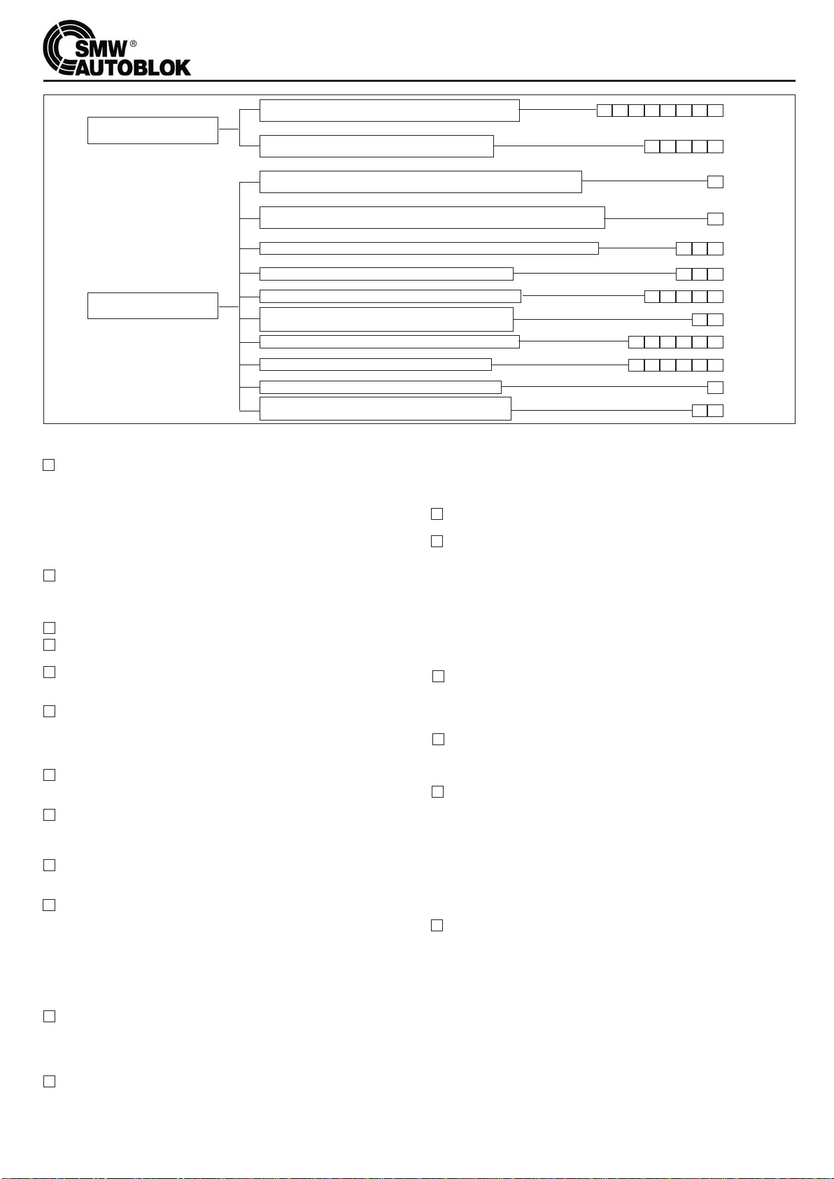
14
LOESUNG DER OBEN GENNANTEN PROBLEME
Beachten Sie bitte Zeichnung Seite 24.
1Dies ist die schwerwiegendste Beschädigung, die beim Spannzylinder auftre-
ten kann, d.h. der rotierende Drehzuführungskörper hat sich zusammen mit
dem stationären Zuführring festgesetzt. Diese Situation tritt auf, wenn das Öl,
das dem Spannzylinder zugeführt wird, nicht sauber und frei von metallischen
PartikeIn oder anderen Fremdkörpern ist. Die Ursachen hierfür sind, wenn:
- die ÖIfilter unterdimensioniert, beschädigt oder verstopft sind.
- der Hydraulikkreislauf bzw. die Zuführrohre nicht komplett sauber sind.
Weitere Ursachen entnehmen Sie bitte Pos. 2 bis 6. Die möglichen
Lösungen für diese Probleme entnehmen Sie bitte den Pos. 7 und 8.
2Verwendung von ungeeignetem Hydrauliköl. Kaltes Öl mit zu hoher
Viskosität verursacht eine sehr hohe Erwärmung durch Viskosereibung bei
hohen Drehzahlen. Bereits bei normaler Anwendung wird eine Überhitzung
verursacht.
3Eine Zylinderrotation hat ohne Hydraulikdruck stattgefunden.
4Die Hydraulikanschlüsse, haben ein konisches oder ein zu langes Gewinde,
das eine Deformation des Zuführringes verursacht.
5Die Hydraulikzuführung über Schläuche oder Rohre bzw. der Leckölablauf oder
die Verdrehsicherungsgabel wirken einen Zwang auf die Drehzuführung des
Spannzylinders aus und beschädigen die Lager.
6Für die Anwendung wurde eine Zusatzeinrichtung benötigt, die nicht korrekt
angebaut wurde (Hohlspindelanschlag, Führungsrohre etc.). Diese führen
einen Zwang auf den Ölzuführungsring aus oder bewirken abnormale
Schwingungen oder Schläge, die sich auf die Geometrie des Spannzylinders
auswirken.
7Bei nur leichten Kontaktspuren empfehlen wir, die Drehzuführung zu demontie-
ren und die Kontaktstellen mit einem feinen Abziehstein nachzuarbeiten. Die
Lager sind hierbei zu ersetzen. Vor Montage alle Teile bitte sorgfältigst reinigen.
8Wenn die Kontaktspuren sehr stark sind, ist es sehr schwierig den
Spannzylinder zu zerlegen und zu reparieren. In diesem Fall empfehIen wir den
Spannzylinder ins Herstellerwerk einzuschicken oder durch einen autorisierten
Fachmann reparieren oder ersetzen zu lassen.
9Stellen Sie sicher, dass maschinenseitig kein Alarmsignal ansteht, das die
Bedienung verhindert. Überprüfen Sie die elektrischen Schaltkreise und die
Betätigungseinrichtungen.
10 Überprüfen Sie, ob die Hydraulikeinrichtungen für den Spannzylinder in
Ordnung sind und den korrekten Hydraulikdruck liefern. Überprüfen Sie
folgendes:
A) Ölstand im Hydrauliktank
B) Korrekte Funktion der Hydraulikpumpe
C) Die Druckfilter müssen funktionsfähig sein
D) Die Magnetventile müssen funktionsfähig sein und dürfen keine
Beschädigungen haben
E) Alle Anschlüsse müssen korrekt miteinander verbunden sein
11 Verringern Sie den eingestellten Hydraulikdruck auf nicht weniger als 1/3 im
Verhältnis zum ursprünglich eingestellten Druck in einem Schritt. Ansonsten
arbeiten die Rückschlagventile nicht mehr und verhindern den Kolbenhub. Wir
empfehlen, den Systemdruck in kleinen Schritten zu reduzieren und den
Spannzylinder zwischen den einzelnen Druckstufen jeweils zu betätigen.
12 Eines der beiden Sicherheitsventile hat sich in seinem Ventilsitz festgesetzt.
Dies kann verschiedene Gründe haben (verschmutztes Öl, Überdruck, Kor-
rosion, Veränderungen der Temperatur, Verschleiß der Innenteile, des
Sicherheitsventils). Stellen Sie den Hydraulikdruck ab und öffnen Sie die beiden
Entlüftungsschrauben A und B (siehe Seite 24). Beachten Sie, dass eine der
beiden Zylinderkammern noch unter Druck steht. Nach dem Öffnen dieser
Entlüftungsschrauben tritt eine geringe Menge Öl aus. Hierdurch werden die
Rückschlagventile druckentlastet. Setzen Sie die Entlüftungsschrauben wieder
ein. Sollte sich der Kolben des Spannzylinders immer noch nicht bewegen, wird
es notwendig, eines oder beide Rückschlagventile, auszutauschen (siehe
Anleitung).
13 Überprüfen Sie, dass das verwendete Zugrohr nicht zu lang (oder zu kurz) ist,
und somit einen mechanischen axialen Stop des Kolbenhubes herbeiführt.
14 Die Abdichtung zwischen der stationären ÖIzuführung und dem rotierenden
Teil des Spannzylinders wird mittels einer Labyrinthabdichtung gewährlei-
stet. Diese kann nicht beschädigt werden. Daher sind alle auftretenden
Leckagen in diesem Bereich durch fehlerhaften Leckölablauf bedingt.
Lesen Sie die Pos. 3.4 und überprüfen Sie folgendes:
A) Der Leckölablauf muß vertikal nach unten erfolgen.
B) Der Leckölablauf hat über seine gesamte Länge den gleichen Querschnitt.
C) Der Leckölablauf hat ein gleichmäßiges Gefälle vom Spannzylinder bis zur
Hydraulikeinheit ohne Taschen zu bilden.
D) Der Einlaufstutzen für das Lecköl muss über dem Ölniveau der
Hydraulikeinheit liegen, niemals darunter.
15 Überprüfen Sie sorgfältig den Bereich wo das ÖI austritt. Wenn es an der
Vorderseite zwischen dem vorderen Körper (1) und der Kolbenstange oder
an der Rückseite zwischen Scheibe (8) und Kolbenstange ist (die rotieren-
den Teile), ist es notwendig, die Dichtungen Nr. (30) und (36) zu ersetzen
(siehe Ersatzteilliste S. 24).
16 Vorausgesetzt die Hydraulikeinheit der Maschine ist von ihrer Größe her
korrekt ausgelegt, bestehen noch folgende Fehlerquellen:
- im Hydraulikkreislauf
- im Spannzylinder
17 Probleme im Hydraulikkreislauf:
A) Die Druckfilter sind verstopft und erlauben nicht den vollen Durchfluss der
Pumpenleistung. In diesem Fall bitte Filtereinheiten ersetzen. Beachten Sie
bitte, dass der Druckfilter einen Filtereinsatz mit 10 µm Feinheit haben muss.
Dieser muss alle 6-8 Monate ersetzt werden.
B) Die Pumpe ist verschlissen und bringt nicht mehr die volle Förderleistung.
Überprüfen Sie die Förderleistung, sollte sie nicht ausreichend sein, erset-
zen Sie die Pumpe.
C) Die Magnetventíle öffnen nicht vollständig und reduzieren somit den
Durchflußquerschnitt. Dies kann durch Verschleiß der Ventile oder durch
Verschmutzung hervorgerufen werden.
18 Probleme im Hydraulikzylinder: Um festzustellen, ob das Problem im
Hydraulikkreislauf oder im Zylinder liegt, setzen Sie 2 Verbindungsstücke mit 2
Manometer in die Entlüftungsbohrungen A und B ein (siehe Seite 24). Überprü-
fen Sie folgendes:
a) Druck darf nur in der druckbeaufschlagten Kammer sein, nur in der druck-
losen z. B. Druck in A, kein Druck in B oder umgekehrt.
b) Dass der Druck in der druckbeaufschlagten Kammer nur wesentlich gerin-
ger als der Systemdruck ist.
Die Probleme im Zylinder können hervorgerufen werden durch:
A) Verschleiß oder Beschädigung der Kolbendichtung Nr. (33) (siehe Seite
24). In diesem Fall ist die Dichtung zu ersetzen.
B) Eines der Maximaldruckventile (20) ist geöffnet. Dies kann durc
h
Verschmutzung oder durch einen unkorrekten Sitz der Druckfedern
entstehen. Versuchen Sie, das Ventil einige Male zu be- und
entIasten, indem Sie den Hydraulikdruck an- und abstellen. Sollte das
Ventil immer noch verklemmt sein, ist es notwendig, den kompletten
Zylinder zu demontieren und die Innenteile des Maximaldruckventiles
zu ersetzen.
Der Zylinder läßt sich
nicht rotieren
Der Zylinder arbeitet
nicht korrekt.
Der Zylinder rotiert nicht, das rotierende Teil und das
stationäre Teil haben sich zusammen festgesetzt.
Der Kolben des Spannzylinders hat sich festge-
setzt und macht keine Axialbewegung mehr.
Der Zylinder hat eine Leckage an der Vorder-bzw. Rückseite der
Drehzuführung (zwischen dem umlaufenden und stationären Teil).
Der Zylinder hat eine Leckage zwischen dem Zylinderkörper bzw. dem
vorderen Flansch und der Kolbenstange (Vorder-oder Rückseite).
Der Kolben des Zylinders bewegt sich axial nur sehr langsam.
Der Zylinder macht nicht den kompletten Axialhub.
Die Temperatur des Spannzylinders übersteigt 70° C
Geräuschentwicklung während der
Axialbewegung des Kolbens im Spannzylinder
Der Zylinder macht Geräusche während der Rotation.
Während der Rotation treten Vibrationen auf.
Kühlmittel tritt aus der Überlaufbohrung C aus.
Kühlmittel ist in den Hydraulikkreislauf und in das
Hydraulik-Aggregat eingedrungen.
1 2 3 4 5 6 7 8
13
14
15
18
21
23
25
27
31
32
3433
30292865
266543
24
22652
2019
1716
1211109
PROBLEME, URSACHEN UND LÖSUNGEN BEI VNK ZYLINDERN

PROBLEME, URSACHEN UND LÖSUNGEN BEI VNK-ZYLINDERN
15
19
Normalerweise wird nur ein Teil des kompletten Zylinderhubs zur Betätigung von
Standardfuttern benötigt. Bei der Bestimmung der Länge des Zugrohres achten Sie
bitte darauf, dass die vordere und hintere Endlage im Zylinder erreicht wird. Wenn
das Zugrohr falsch ausgelegt bzw. gefertigt wurde, macht der Spannzylinder nicht
den korrekten Hub, der für das jeweilig verwendete Futter notwendig ist.
20 Eine Verkürzung des Zylinderhubes bedeutet auch eine Verkürzung des Ba-
ckenhubes. Dies kann durch unbeabsichtigtes Lösen der Zugrohrverschraubung
erfolgen. In diesem Fall schrauben Sie das Zugrohr wieder korrekt ein und sichern
Sie es gegen verdrehen.
21 Überprüfen Sie das Spannfutter auf evtl. Probleme.
22 Das Ansteigen der Öltemperatur wird nur sehr selten vom Spannzylinder verur-
sacht. Es wird hauptsächlich durch den Hydraulikkreislauf verursacht. Eine kor-
rekt arbeitende Hydraulikeinheit sollte auch unter Vollast innerhalb eines
Temperaturbereiches von 35° C - 65° C bleiben. Dies ist der beste
Temperaturbereich um mit dem Spannzylinder zu arbeiten. Sollte die Öltempe-
ratur im Betrieb über 70° C ansteigen, ist es notwendig, das Ölvolumen in der
Hydraulikeinheit zu erhöhen oder einen Ölkühler zu verwenden.
23 Überprüfen Sie den ÖIstand im Hydraulikaggregat. Ein zu niedriger Ölstand
verursacht höhere Temperaturen.
24 Eine unzureichende Schmierung des Spannfutters kann Geräusche während des
Spannvorgangs verursachen. Zerlegen Sie das Futter und schmieren Sie es mit der
vorgeschriebenen SMW-AUTOBLOK Gleitpaste KO5 ab.
25 Beschädigung oder Bruch des Zugrohres oder des Verbindungsgewindes kann
ebenfalls abnormale Geräusche verursachen. In diesem Fall sind die beschä-
digten Teile unbedingt zu ersetzen.
26
Sollten Vibrationen auftreten während der Spannzylinder mit Druck beaufschlagt
wird (bei Verwendung von Kraftspannfuttern mit Innenspannung oder
Spannzangenfuttern), kann dies durch Durchbiegen des Zugrohres aufgrund der
Druckbelastung entstehen. In diesem Fall empfehlen wir den Einsatz von
Stützringen aus Bronze oder Kunststoff, die das Zugrohr am lnnendurchmesser
der Spindelbohrung abstützen.
27
Eine starke Geräuschentwicklung zwischen dem stationären
ÖIzuführungsgehäuse und dem rotierenden Teil des Spannzylinders deutet auf
einen Verschleiß oder Beschädigung der Lager hin. Dies kann durch versch-
mutztes ÖI oder normalen Verschleiß hervorgerufen werden. Austausch der
Lager notwendig - siehe Demontage/Montage, Punkt E, Seite 15
.
28
Überprüfen Sie den korrekten Rund- und Planlauf des Zylinders und des
ZyIinderfIansches (siehe Anbauanleitung Pos. 2).
29
Überprüfen Sie, ob sich durch Schläge des Stangenmaterials gegen die
Zylinderbohrung oder durch andere Vibrationen die Befestigungsschrauben des
vorderen Zylinderflansches gelöst haben. Dies kann eine Exzentrizität dieser
Teile verursachen. Überprüfen Sie dieses Problem und beheben Sie es gegebe-
nenfalls.
30
Überprüfen Sie das Zugrohr auf Unwucht, Rundlauffehler oder Durchbiegung
bei Druckbeaufschlagung.
31
Überprüfen Sie folgendes: Entspannen Sie das Werkstück, demontieren Sie die
Aufsatzbacken, das Futter, das Zugrohr, den Zylinder und die Flansche bis keine
Vibrationen mehr entstehen. Das zuletzt demontierte Teil muss dann jeweils
ausgewuchtet werden.
32
Der Kühlmittelablauf ist durch Späne verstopft und behindert den freien Ablauf
des Kühlmittels. Somit tritt es an der Überlaufbohrung C aus. Reinigen Sie den
Kühlmittelablauf. Um ähnliche Probleme in Zukunft zu verhindern empfehlen wir,
einen Sicherheitsablaufstutzen in das 3/4“-Gewinde des Verschlußstopfens D
einzuschrauben und mit dem Kühlmitteltank zu verbinden.
33
Wenn der Kühlmittelablauf verstopft ist, kann es vorkommen, dass die eintretende
Kühlmittelmenge durch die Zylinderbohrung größer ist als die Kühlmittelmenge, die
durch das Überlaufloch C ausfließen kann. Damit erhöht sich der Kühlmittelstand
und das Kühlmittel fließt durch die Labyrinthabdichtung in den Spannzylinder.
Beachten Sie die Anweisungen von Pos. 31.
34
Dasselbe Problem wie bei Pos. 32, nur in diesem Fall ist das Überlaufloch C ver-
stopft. Reinigen Sie die Überlaufbohrung und befolgen Sie die Anweisungen von
Pos. 32.
Demontage
A.
Arbeitsschritte bevor der Zylinder von der Maschine abgebaut wird.
a1.
Reduzieren Sie den Hydraulikdruck auf ca. 10 bar während der Zylinder betätigt wird.
a2.
Bringen Sie den Zylinderkolben in Mittelstellung.
a3.
Stellen Sie den Hydraulikdruck ab und lösen Sie die Zuleitungen sowie den
Leckölablauf.
a4.
Blasen Sie mit Pressluft abwechselnd in die Anschlüsse und fangen Sie das am
jeweils anderen Anschluß austretende Öl auf.
a5.
Fahren Sie den Kolben in die hintere Endstellung.
a6.
Demontieren Sie die hintere Abdeckung (21/1) der Kühlmittelauffangschale.
a7.
Demontieren Sie den Schaltring (24) und die Mutter (23).
a8.
Entfernen Sie die Schrauben 46 und demontieren Sie die Kühlmittelauffangschale.
Die komplette Einheit kann nun abgenommen werden ohne die Wegekontrolle zu
verstellen. Achten Sie darauf, die Kabel für die berührungslosen Endschalter, die
am Gehäuse befestigt sind, nicht zu beschädigen.
a9.
Demontieren Sie den Spannzylinder von der Maschine und legen Sie ihn sicher
auf eine Werkbank.
B.
Demontage des Kolbens
b1.
Demontieren Sie die beiden Entlüftungsstopfen A und B und die zugehörigen
Dichtungen (siehe Zeichnung Seite 24).
b2.
Öffnen Sie die Befestigungsschrauben Nr. 47 am Flansch (2).
b3.
Demontieren Sie den vorderen Körper (1) mit Hilfe der Abdrückgewinde.
b4.
Demontieren Sie den Kolben (3), durch leichtes Klopfen mit einem
Kunststoffhammer auf die Rückseite der Kolbenstange. Jetzt können
Routinewartungsarbeiten durchgeführt werden.
C.
Wenn die Maximaldruckventile ersetzt werden müssen, befolgen Sie bitte
folgende Anweisungen:
c1.
Es ist möglich, nur die lnnenteile der Maximaldruckventile (20) zu ersetzen, da
das Gehäuse in den Kolben fest eingebaut ist.
c2.
Messen Sie die Stellung des Verschlußstopfens, der die Vorspannungsfeder in
Position hält.
c3.
Demontieren Sie den Verschlussstopfen. (Bitte beachten Sie, dass der
Verschussstopfen mit Loctite gesichert ist).
c4.
Entnehmen Sie das Ventil und ersetzen Sie es durch neue Teile in der gleichen
Reihenfolge wie Sie die alten Teile ausgebaut haben.
c5.
Setzen Sie den Verschussstopfen in die gleiche Position wie unter Punkt c2 ein.
Sichern Sie den Verschussstopfen mit etwas Loctite. Die Position des
Verschlussstopfens ist sehr wichtig, da diese die Vorspannung der Feder beein-
flußt und somit das Öffnen des Ventiles reguliert.
D.
Sollte es notwendig sein die Sicherheitsventile zu ersetzen, auch wenn der
Spannzylinder noch auf der Machine ist, folgen Sie bitte folgenden
Instruktionen:
d1.
Am Umfang des Zylinders befinden sich 4 Bohrungen mit Verschlußstopfen.
Jeweils eine kleine und eine große (siehe Sektion E-E).
d2.
Entfernen Sie die 4 Verschussstopfen Teil (16) und Teil (17) (siehe Zeichnung).
.
d3.
Setzen Sie einen Bolzen in die kleinere Bohrung ein.
d4
Schieben Sie das Ventil mit dem Bolzen nach hinten bis es aus der größeren
Bohrung herauskommt.
d5.
Notieren Sie sich die Richtung, in der das Rückschlagventil eingebaut war.
d6.
Setzen Sie das neue Ventil in der gleichen Richtung wieder ein.
d7.
Setzen Sie die Verschlussstopfen wieder ein.
E.
Demontage der hydraulischen Drehzuführung bei Lagerschaden:
Nur von geschultem Fachpersonal in Verbindung mit Sonderwerkzeug
durchzuführen.
Wenn möglich, bitte den Zylinder zu einem SMW-Autoblok Kundendienststelle
schicken. Wenn es nicht möglich ist, bitte wie folgt verfahren:
e1.
Nehmen Sie die Abdeckung (6) ab.
e2.
Öffnen Sie die Schrauben (43) demontieren Sie die Scheibe (8), und ziehen Sie
die komplette Öleinheit (5+10+11/B+12/B) mit einem Auszieher ab.
e3.
Demontieren Sie die Scheibe (19).
e4.
Demontieren Sie die Vorderbuchse (29) mit einem Montierhebel. Dieser soll zwi-
schen dem Vorderdeckel (7) und dem Lager selbst eingekeilt werden. Um die
Einführung zu unterstützen, gibt es im Deckel 2 Auskehlungen.
e5.
Die Einheit 5+10+11/B+12/B braucht normalerweise keine Demontage. Sollte es
notwendig sein, nehmen Sie die Schraube (9) ab (1 oder 2, nach der Größe) und
ziehen Sie den Ring (5) aus dem Kasten (10) heraus.
Zusammenbau
A.
Montage des Kolbens (3)
a1.
Setzen Sie die Dichtungen (31) - (32) - (33) - (36) ein. Beachten Sie, dass die
Dichtungen leicht mit einem geeigneten Fett eingefettet werden, um den
Zusammenbau zu erleichtern und eine Beschädigung der Dichtungen zu verhindern.
a2.
Setzen Sie den Kolben wieder in seine Position ein. Gegebenenfalls kann die
Montage durch leichte Schläge mit einem Kunststoffhammer auf die Vorderseite
durchgeführt werden. Achtung: Achten Sie auf die korrekte Lage der
Maximaldruckventile, deren Gehäuse auch als Verdrehsicherung dient. Sie müssen
in die jeweils zugehörige Bohrung im Zylinderkörper eintauchen können.
B.
Montage des vorderen Körpers (1)
b1.
Nach dem korrekten Einsetzen der Dichtung (30), setzen Sie den Körper (1) wie-
der auf den Flansch (2) auf. Achten Sie auf die korrekte Winkellage zu den
Maximaldruckventilen. Ziehen Sie die Schrauben (47) leicht an.
b2.
Zentrieren Sie den vorderen Flansch (2) zum Zylinderkörper Nr. 1.
b3.
Ziehen Sie die Befestigungsschrauben (47) mit dem korrekten Drehmoment
über Kreuz an und setzen Sie die Verschussstopfen A und B wieder ein.
C.
Montage des Ölzuführungsgehäuses (5 + 10)
c1.
Montieren Sie das Vorderlager (29) und die Scheibe (19) auf den Flansch (2).
c2.
Montieren Sie die Dichtungen (40), Einbaulage beachten. Montieren Sie das
Drehverteilergehäuse (10) auf den Innenring (5). Befestigen Sie das
Drehverteilergehäuse mit den Schrauben (9).
c3.
Fügen Sie die Einheit (5+10) auf den Flansch (2) ein. (Bitte diesen Vorgang sorg-
fältig durchführen)
c4.
Fügen Sie die Dichtung (35) und die Scheibe (8) ein. Ziehen Sie die Schrauben
(43) nur leicht an.
c5.
Montieren Sie die Abdeckung (6).
D.
Anbau des Spannzylinders auf die Maschine.
d1.
Beachten Sie die Anbauanleitung. Richten Sie den Zylinder zur Spindel aus
Rundlauf. Danach ziehen Sie die Befestigungsschrauben mit dem korrekten
Drehmoment über Kreuz an.
d2. Wenn der Zuführring (5) demontiert wurde, zentrieren Sie die Scheibe (8) und
ziehen Sie die Schrauben (37) korrekt an.
E.
Anbau der Külmittelauffangschale und der Kolbenhubkontrolle
e1
Montieren Sie die Kühlmittelauffangschale (21) mittels der Schrauben (46).
Achten Sie darauf, dass die Zuleitungen den berührungslosen Endschalter nicht
beschädigen.
e2
Montieren Sie den Schaltring (24) und die Mutter (23).
e3.
Montieren Sie die Abdeckung (21/1).
DEMONTAGE UND ZUSAMMENBAU DER VNK-ZYLINDER -
Beachten Sie bitte Zeichnung Seite 24

16
1. GÉNÉRALITÉS
1.1 Les cylindres hydrauliques VNK sont ce qu’il y a de plus avancé actuel-
lement sur le marché, en ce qui concerne vitesse, sécurité et fiabilité; ces
cylindres disposent de toutes les caractéristiques de sécurité deman-
dées par les normes internationales.
1.2 VALVES DE SÉCURITÉ. Les cylindres VNK ont deux clapets antiretour
incorporés qui maintiennent la pression d’alimentation dans les
chambres, même en cas de réduction ou d’interruption de la pression.
La pression minimum prévue est de 5 bar.
1.3 VALVES DE PRESSION MAXI. Dans chaque chambre des cylindres
VNK il y a une valve de pression maxi qui s’ouvre automatiquement en
cas de surpression.
1.4 CONTRÔLE DE LA COURSE DU PISTON. A l’arrière du cylindre, est
prédisposé un système de contrôle de la course du piston par des
détecteurs de proximité (qui ne sont pas fournis), ou bien par un systè-
me voir les instruction sur les manuels spécifiques.
1.5 FIXATION AVEC VIS POSTÉRIEURES. Les cylindres VNK peuvent être
fixés au flasque par une serie de vis postérieures (schéma 2) qui permet-
tent de fìxer le cylindre directement sur la poulie en l’approchant au rou-
lement arrière de la broche.
1.6 Les cylindres hydrauliques sont livrés soigneusement emballés et donc
protégés d’éventuels coups, dus à une manipulation normale pendant le
transport. Les parties métalliques externes, soumises aux risques d’oxy-
dation, sont protégées par un liquide antirouille. Ce produit, au moment de
la mise en service, doit être soigneusement enlevé en utilisant un pinceau
trempé de kérosène; après ce nettoyage essuyer le cylindre.
2. MONTAGE DU CYLINDRE SUR LA BROCHE DE LA MACHINE
2.1 Il y a différentes possibilités de fixation du cylindre sur la broche de la
machine, avec un flasque d’adaptation, suivant les différentes configura-
tions de l’arrière de la broche.
2.2
Z
Pour pouvoir tourner à hautes vitesses, avec déséquilibres et
vibrations minimum, il est indispensable que le cylindre soit le plus près
possible au roulement postérieur de soutien de la broche et qu’il tourne
parfaitement centré par rapport à l’axe de rotation de la broche même.
Il est, donc, indispensable, avant de monter le cylindre, de contrôler que
le plan d’appui du flasque et le diamètre de centrage soient exécutés cor-
rectement et suivant les critères de précision, ci-dessous:
Schéma 1
Diamètre
Cylindre ≤170/77 ≥200/86
Concentricité A 0,01 0,015
Planéité B 0,005 0,010
2.3 Une fois vérifiée la précision du flasque de fixation, on procède au
montage du cylindre sur le flasque même. Visser légèrement les vis de
fixation et procéder au centrage du cylindre de façon à ce que la rotation
soit réalisée avec les critères de précision suivants:
Schéma 2
Visser à fond les vis avec les couples de serrage reportés dans le tableau ci-
dessous:
Dimension nominale de la vis Classe 12.9
F (KN) F (KN) M (Nm)
M8 16 23
M10 26 45
M12 38 77
M16 72 190
M20 110 370
2.4 Les cylindres VNK sont prévus avec 2 filetages pour le raccord au tirant
d’actionnement, de façon à s’adapter au mieux aux dìfférents diamètres
du passage de la broche de la machine. Les deux filetages sont ceux
indiqués par F1 et F2 du plan de la page 3, et ont tous les deux un dia-
mètre de centrage (respectivement K1 et K2). En construisant le tirant,
après avoir choisi quel filetage utiliser, prévoir un centrage sur le diamètre
K1 ou K2 de 5 mm. de long.
3. RACCORDEMENT DU CYLINDRE AVEC LES TUYAUX D’ALIMEN-
TATION ET DE DRAINAGE.
3.1 n Tous les raccordements d’alimentation et de drainage doivent être
réalisés avec des tuyaux flexibles; il faut éviter tous tuyaux rigides
ou semirigides qui pourraient exercer une poussée axiale sur le
collecteur et endommager les roulements.
3.2 n Utiliser uniquement des raccords et des tuyaux hydrauliques avec
filetages cylindriques et avec rondelles d’étanchéité. NE JAMAIS UTILI-
SER DES RACCORDS OU DES TUYAUX AVEC FILETAGE CONIQUE.
Schéma 3
3.3
Z
Le collecteur d’alimentation et de drainage (partie fixe du cylindre)
doit être maintenu en position par un support ancré à la machine (Schéma
3). Ce support doit avoir une fente de guidage qui s’engage, préférable-
ment, sur le raccord de drainage, ou sur le pion revêtu de caoutchouc fixé
sur la partie supérieure du collecteur, le support ne doit pas exercer de
poussées axiales et doit avoir 2 ou 3 mm de jeu radial. Ce support main-
tient les raccords de drainage de l’huile et du liquide réfrigérant verticaux
de façon à faciliter le reflux par gravité.
INSTRUCTIONS D’UTILISATION ET ENTRETIEN DES CYLINDRES
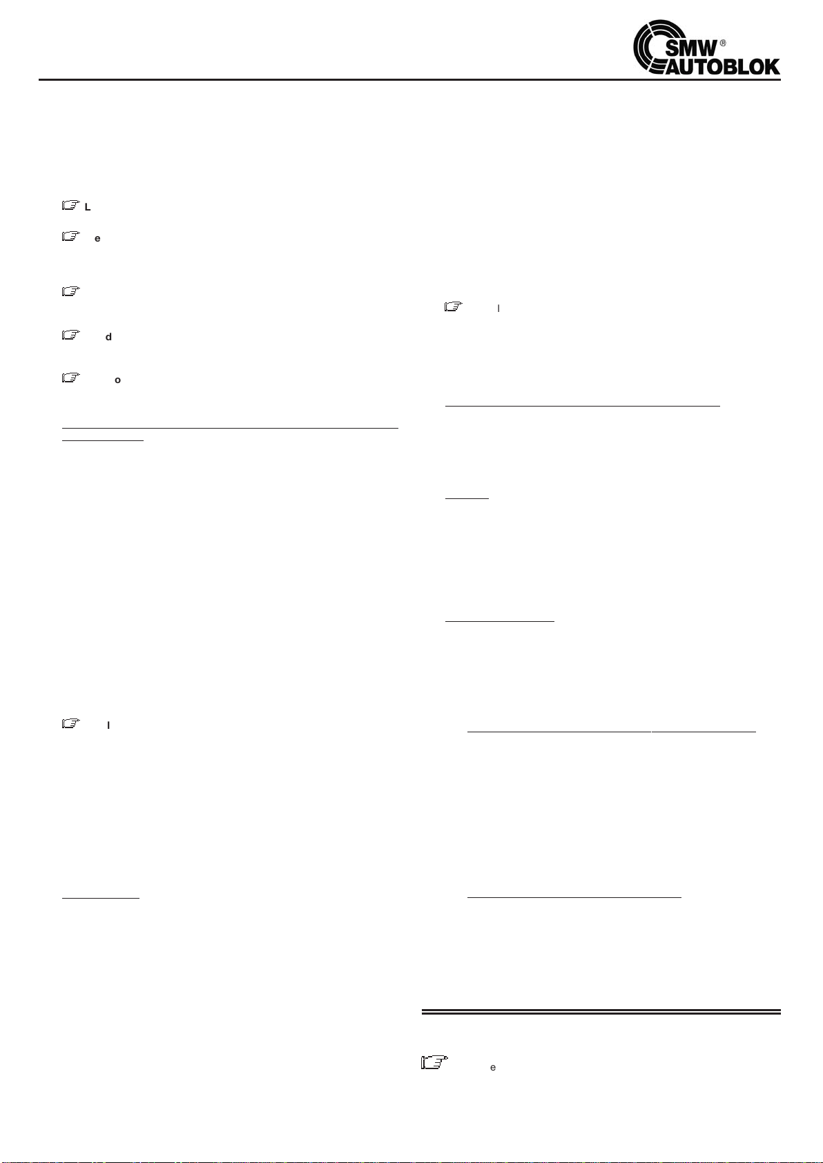
17
3.4 IMPORTANT:
Sur tous les cylindres hydrauliques rotatifs à centre ouvert l’étanchéité,
entre la partie fixe (collecteur d’alimentation) et la partie tournante est
assurée par des joints mécaniques type labyrinthes. Puisque le drainage
de l’huile est fait normalement par gravité, il faut une certaine différence
de niveau entre le raccord de drainage et le niveau de l’huile dans la cen-
trale hydraulique. Pour obtenir un bon drainage de l’huile et éviter des
débordements des labyrinthes, il faut suivre les indications suivantes:
A)
Z
Le raccord de drainage de l’huile doit toujours être maintenu en
position verticale.
B)
Z
Le tuyau de drainage doit être flexible mais ne doit pas
s’amollir à la chaleur, en réduisant la section de passage de l’huile;
nous conseillons des tuyaux en plastique avec l’intérieur en spirale
métallique qui en maintient la section constante.
C)
Z
Le tuyau de drainage doit avoir une pente continue jusqu’à la
centrale; EVITER ABSOLUMENT DES SIPHONS qui pourraient créer
des contrepressions et des engorgements du tuyau.
D)
Z
Le drain dans la centrale hydraulique doit être TOUJOURS
AU-DESSUS du niveau de l’huile et JAMAIS AU-DESSOUS pour
éviter de possibles contrepressions.
E)
Z
Le bouchon de la centrale hydraulique ne doit pas être
hermétique mais doit avoir une aération qui doit toujours être
maintenue libre et propre.
4. CENTRALES HYDRAULIQUES DE COMMANDE ET HUILES
CONSEILLEES
4.1 La capacité du réservoir de la centrale hydraulique devrait être au moins
4 fois le débit de la pompe en I/min. (par exemple avec un débit de la
pompe de 12 I/min. il faut un réservoir de 45-50 litres) afin d’éviter une
surchauffe excessive de l’huile; en cas où ce ne serait pas possible nous
conseillons d’utiliser des systèmes de réfrigération de l’huile. La tempé-
rature optimale pour le bon fonctionnement du cylindre hydraulique est
comprise entre 35° et 60°C (70° C peuvent être de toute manière rejoints
sans problème); il est donc conseillé de prévoir la centrale hydraulique
afin d’obtenir ces résultats, même dans des conditions extrêmes
d’utilisation de la machine.
4.2 Le système hydraulique doit avoir un filtre en aspiration avec des mailles
de 50-60 micron et un filtre en pression de 10 micron; nous conseillons
de contrôIer périodiquement l’intégrité des filtres. Prévoir la substitution
du filtre en pression tous les 6-8 mois.
4.3 Les cylindres VNK ont des grands conduits d’alimentation de l’huile;
néanmoins, pour obtenir une bonne vitesse de dépIacement du piston, il
est nécessaire que le circuit d’alimentation ait des grands conduits, des
tuyaux les plus courts possible, en évitant des rétrécissements et en pré-
voyant des électro-vannes avec grandes sections de passage de l’huile.
4.4 HUILES CONSEILLEES:
Z
L’huile la plus appropriée pour l’actionnement des cylindres hydrau-
liques rotatifs est identifiée à la norme ISO 3448 avec le type HM32.
A titre d’exemple, nous citons, ci-dessous, quelques huiles parmi celles
les plus commercialisées:
AGIP - OSO 32
ESSO - NUTO - H32 (ou TERESSO 32)
MOBIL DTE 24 (ou DTE LIGHT)
SHELL - TELLUS 32
n Nota: Nous déconseillons l’utilisation d’huiles avec une
viscosité supérieure car elles pourraient créer de sérieux problèmes lors
de la rotation du cylindre à hautes vitesses avec l’huile froide. Prévoir de
vidanger l’huile tous les 12-18 mois maximum.
5. PRECAUTIONS
5.1 n Avant de raccorder le cyIindre au circuit hydraulique il faut s’assurer
qu’il n’y ait pas des impuretés métalliques ou des corps étrangers en
circulation; nettoyer avec soin les conduits et l’intérieur des tubes en
soufflant de l’air comprimé.
IL EST INDISPENSABLE, afin de s’assurer que le circuit soit propre, de
relier les 2 tuyaux d’alimentation directement entre-eux et faire circuler
l’huile pour au moins 30 minutes à la pression maximale afin que le
fluide soit soigneusement filtré. Nettoyer les filtres après cette opération.
5.2 Avant la mise en fonctionnement définitive du groupe mandrin-cylindre
nous conseillons ces simples opérations:
A) n Avec le cylindre à l’arrêt, faire quelques mouvements d’ouverture et
fermeture à pression mini en vérifiant qu’il n’y ait aucun empêchement au
mouvement du cylindre, ni aucune perte éventuelle de liquide.
B) n Faire tourner le mandrin à petite vitesse pour à peu près 15 minutes
en vérifiant que les tuyaux d’arrivée, de drainage et la fourche antirota-
tion ne procurent aucun empêchement à la rotation.
C) n Augmenter la pression au régime normal et exécuter encore 8 à 10
mouvements d’ouverture et fermeture.
D) n Augmenter progressivement la vitesse de rotation, en vérifiant que
l’huile d’alimentation ait une température minimum de 35° avant de
rejoindre la vitesse maxi.
5.3 IMPORTANT
A) n Ne jamais tourner sans pression d’huile. Ceci causerait l’endom-
magement des roulements et le grippage de l’anneau de distribution et
du corps.
B) n Ne jamais actionner le cylindre à hautes vitesses avec l’huile
froide; ceci pourrait endommager les roulements et l’anneau de
distribution. Nous conseillons d’effectuer quelques mouvements
d’ouverture et fermeture à basse vitesse de rotation, avant de
commencer le travail.
C)
Z
Les cylindres hydrauliques VNK ont sur le carter de récupération du
liquide refrigérant un trou de sécurité pour éviter, qu’en cas d’engorge-
ment du tuyau de drainage, le liquide même se mêle à l’huile (C et D, voir
page 24).
L’opérateur devra vérifier périodiquernent qu’il n’y ait aucun
entassement de copeaux dans le carter et dans le tube de drainage
du liquide réfrigérant.
6. ANALYSES DES RISQUES ET NORMES DE SECURITE.
6.1 RISQUES DIRECTS
n Les cylindres hydrauliques VNK sont construits en deux parties,
dont une fixe et une tournante à vitesse élevée. Il existe la possibilité
que les deux parties puissent gripper si les instructions de montage,
utilisation et entretien ne sont pas observées correctement.
A) Montage
a1) Lire avec attention et suivre les indications des paragraphes 3-4 et 5 de
ce manuel (en particulier les § 5.1 - 5.2 et 5.3).
a2) Lire attentivement les causes possibles d’un éventuel grippage décrites
dans le “guide à la solution des problèmes” aux paragraphes de 1 à 8.
a3) n En particulier, au moment de la première mise en rotation du
cylindre AUCUN OPÉRATEUR NE DOIT SE TROUVER EN PROXIMITÉ
DU CYLINDRE.
B) Utilisation et entretien
Pour éviter de gripper pendant l’usinage, suivre les indications des
paragraphes 3 - 4 et 5 de ce manuel.
6.2 RISQUES INDIRECTS
On considère risques indirects ceux qui peuvent dérivés au serrage des
pièces sur les mandrins ou porte-pinces en conséquence d’un mauvais
fonctionnement ou d’une mise en service erronée des cylindres VNK.
A) n La machine doit être autorisée à tourner seulement après:
a1) Avoir contrôlé avec un pressostat que le circuit d’alimentation soit pres-
surisé à la pression fixée.
a2) Avoir contrôlé avec 2 ou plus détecteurs de proximité, ou avec méthode
différente, la position de “pièce bloquée”.
B) n Les circuits électriques et hydrauliques de la machine doivent être
prévus de façon à EXCLURE LA POSSIBILITE D’OUVERTURE ET
FERMETURE DE LA PIECE PENDANT LA ROTATION DE LA BROCHE.
C) n Il faut utiliser des électro-vannes à double solinoïdes à position fixe,
afin qu’en cas de manque de courant électrique la position soit
maintenue et que les mors du mandrin ne s’ouvrent pas.
D) n Contrôle des valves de sécurité du cylindre
À intervalle d’un an de la mise en service du cylindre, nous conseillons de
vérifier, l’efficacité des valves de sécurité. Pour cette opération il faut
monter deux manomètres (non fournis) en utilisant deux raccords
appropriés sur les trous A et B (voir page 24). Envoyer la pression à 30
bar alternativement dans les deux chambres du cylindre et vérifier qu’en
supprimant l’alimentation, la pression reste au-dessus de 10 bar pour au
moins 4-5 minutes.
LEGENDE
Z
= Risque d’endommagement du cylindre et/ou du mandrin et/ou de la
machine.
n=En plus de l’endommagement du cylindre, mandrin, machine; risques
physiques pour les opérateurs.
INSTRUCTIONS D’UTILISATION ET ENTRETIEN DES CYLINDRES

18
Le cylindre, ne
fonctionne pas
Le cylindre fonctionne
mais pas correctement
Le cylindre ne tourne pas; la partie tournante est
bloquée par rapport à l’anneau de distribution fixe
Le piston du cylindre est bloqué et
ne fait pas la course axiale
Le cylindre perd de l’huile à l’avant et/ou à l’arrière de l’anneau
de distribution (entre la partie fixe et la partie toumante)
Le cylindre perd de l’huile entre le corps, le flasque
et la tige du piston (à l’avant ou à l’arrière)
Le cylindre fait la course axiale mais bouge très lentement
Le cylindre ne fait pas complètement la course axiale
La température du cylindre est élevée à plus de 70°C
Bruit pendant la course axiale du piston
Bruit pendant la rotation
Vibrations pendant la rotation
Le liquide réfrigérant déborde du trou de sécurité
Le liquide réfrigérant a pénétré dans le circuit hydraulique et dans la centrale
1 2 3 4 5 6 7 8
13
14
15
18
21
23
25
27
31
32
3433
30292865
266543
24
22652
2019
1716
1211109
GUIDE A LA SOLUTION DES PROBLEMES SUR CYLINDRES VNK
SOLUTION
Nota: Prendre comme point de repère le plan de la page 24.
1C’est le dommage le plus grave que peut subir le cylindre; ceci indique que la
partie tournante (corps) de la distribution hydraulique est grippée sur la par-
tie fixe (anneau de distribution). Une des causes peut être l’utilisation d’huile
sale avec des impuretés métalliques ou des corps étrangers en suspension,
ce qui serait dû à:
- Les filtres pour l’huile sont insuffisants ou endommagés
- Le circuit et les tuyaux hydrauliques n’ont pas été nettoyés soigneusement
D’autres causes peuvent être recherchées aux paragraphes suivants, du n. 2
au n. 6. Les solutions à ce problème sont suggérées aux paragraphes 7 et 8.
2Huile non indiquée; avec une viscosité trop élevée qui provoque un
réchauffement local trop élevé avec l’huile froide à hautes vitesses et
provoque une surchauffe même à régime normal.
3Le cylindre a été mis en service sans pression d’huile.
4On a utìlisé des raccords avec un filetage conique ou trop Iong qui ont
provoqué la déformation de l’anneau de distribution.
5Les tuyaux d’alimentation, le drain de l’huile ou la fourche antirotation ont été
montés de manière à appliquer un effort axial sur l’anneau de distribution en
causant l’endommagement des roulements.
6Des dispositifs auxiliaires ont été montés erronément (arrêt-tirant, guide-tirant,
appui de la pièce) et ont appliqué un effort axial sur l’anneau de distribution ou
sollicitations et coups anormaux qui ont altéré la géométrie du cylindre.
7Si le grippage n’est pas très important, nous conseillons de démonter l’anneau
de distribution, d’enlever avec une pierre abrasive les éventuelles traces de grip-
page et de changer les roulements. Laver soigneusement avant le remontage.
8Si le grippage est très important, le démontage et la réparation deviennent très
difficiles, nous conseillons d’envoyer dle cylindre à un centre de service
“AUTOBLOK” pour la réparation, ou bien de changer le cylindre.
9Vérifier qu’il n’y ait pas de signaux d’alarme dans le système opérationnel de
la machine qui puissent interdire le fonctionnement des commandes; en
particulier vérifier le circuit électrique et les poussoirs.
10 Vérifier que le circuit hydraulique qui commande le mouvement du cylindre
soit efficace et donne la pression nécessaire; contrôler:
A) Le niveau de l’huile dans le réservoir
B) que la pompe fonctionne régulièrement
C) que les filtres ne soient pas engorgés
D) que les électro-vannes ne soient pas bloquées
E) que les tuyaux soient raccordés correcterment
11 S’assurer de ne pas avoir réduit la pression en une seule manoeuvre à 1/3 (ou
moins) de la pression précédemment imposée: ceci provoque l’impossibilité
de piloter les valves de sécurité et donc de commander le mouvement du
piston. Nous conseillons de réduire la pression progressivement en plusieurs
manoeuvres en faisant une ouverture et une fermeture à chaque fois.
12 Pour différentes causes (huile sale, surpression, coups de bélier, variations de
température, usure des éléments internes des valves) une des 2 valves de
sécurité s’est bloquée dans son siège.
Pour la débloquer, nous conseillons d’effectuer les opérations suivantes:
Avec la centrale hydraulique sans pression, dévisser en faisant très attention
(une des chambres du cylindre est encore pressurisée) les deux vis de purge
A et B (voir page 24). En desserrant ces vis l’une d’elles perdera un certain
volume d’huile, et ainsi on pourra de nouveau commander la valve. Remonter
ces vis et mettre en serice le cylindre.
Si après ces opérations le piston ne bouge toujours pas, il faudra changer 1
ou 2 valves de sécurité (voir instructions).
13 Vérifier que le tirant de liaison avec le mandrin ne soit pas trop Iong (ou trop
court) ce qui provoquerait des arrêts axiaux mécaniques qui empêcheraient la
course du piston.
14 Entre l’anneau de distribution fixe et la partie tournante, du cylindre,
l’étanchéité de l’huile est obtenue par des joints mécaniques à Iabyrinthe qui
ne peuvent pas être endommagés; une éventuelle fuite à cet endroit peut
être due UNIQUEMENT À UN DEFAUT DU DRAINAGE DE L’HUILE.
Lire avec attention le paragraphe 3.4 et en particulier vérifier:
A) Que le raccord de drainage de l’huile soit maintenu en position VERTICALE.
B) Que le tuyau de drainage N’AIT PAS DES RETRECISSEMENTS DE SECTION.
C) Que le tuyau de drainage ait une pente continue du cylindre à la centrale SANS
FORMER DES SIPHONS.
D) Que le drain de la centrale hydraulique soit TOUJOURS AU-DESSUS DU
NIVEAU DE L’HUILE ET JAMAIS AU-DESSOUS.
15 Contrôler attentivement le drainage de l’huile; si il y a une fuite d’huile à l’avant
entre le corps (1) et la tige du piston et/ou à l’arrière entre la rondelle (8) et la tige
du piston (qui sont des parties rotatives) il faut changer les joints en caoutchouc
(30) et (36) (voir liste des pièces de rechange page 24).
16 On suppose que le constructeur de la machine ait dimensioné la centrale en
tenant compte des nécessités du débit effectif de l’huile. Si la centrale hydrauli-
que est bien dimensionnée, deux genres d’inconvénients peuvent se produire:
- Problèmes sur l’installation hydraulique
- Problèmes sur le cylindre
17 Problèmes sur l’installation hydraulique:
A) Les filtres sont engorgés et ne permettent pas le passage régulìer du débit de
la pompe. Il faut changer Ies filtres.
N.B. Se rappeler que le filtre d’arrivée de 10 micron est généralement en
papier = en microfibre et doit être changé tous les 6-8 mois.
B) La pompe est usée et ne fournit plus le débit initial. Il faut mesurer le débit en
I/min. et si insuffisant il faut changer la pompe.
C) Les électro-vannes, à cause de l’usure ou d’impuretés intérieures, ne font plus
toute leur course et réduisent la section de passage de l’huile.
18 Problèmes sur le cylindre hydraulique:
Pour déterminer avec certitude qu’il s’agit d’un problème sur l’installation
hydraulique ou sur le cylindre, on conseille de monter (per l’intermédiaire de 2
raccords) 2 manomètres sur les trous A et B (voir page 24) et contrôler:
a) qu’il y ait de la pression alternativement dans une seule chambre du cylindre (
par exemple A = 30 bar B = 0 bar et vice versa).
b) que la pression en A ou B soit seulement de peu inférieure à la pression d’exer-
cice imposée sur la centrale pour le cylindre.
A) Usure ou rupture du joint principal du piston (33) (voir page 24), dans ce cas le
joint doit être remplacé.
B) Une valve di pression maxi (20) est ouverte à cause de l’introduction d’impure-
tés ou dérèglement des ressorts. On conseille de mettre et enlever la pression
plusieurs fois en essayant ainsi de débloquer la valve; si ce n’est pas suffisant il
faut démonter le cylindre et remplacer les parties internes de la valve.

19
GUIDE A LA SOLUTION DES PROBLEMES SUR CYLINDRES VNK
19 Normalement pour le fonctionnement des mandrins standard on n’utilise qu’une
partie de la course totale du cylindre. En déterminant la longueur du tirant de
liaison entre le cylindre et le mandrin, on prévoit la fin de course anterieure sur le
mandrin et la fin de course postérieure sur le cylindre.
Evidemment si le tirant a été dessiné ou réalisé de manière erronée (trop long ou
trop court) le cylindre ne fera pas toute la course nécessaire au mandrin.
20 Une réduction anormale de la course du cylindre (et de la course des mors) peut
être due au dévissage accidentel du tirant. Le revisser correctement et en
bloquer le dévissage.
21 Il peut y avoir des ruptures ou anomalies sur le mandrin: vérifier.
22 L’éIévation de la température de l’huile est due seulement pour une part minime
au cylindre; le plus souvent elle est due à l’installation hydraulique. Une centrale
hydraulique, bien structurée, devrait pouvoir maintenir la température de l’huile,
même en conditions extrêmes d’utilisation, entre les 35° et les 60°C, ce qui est
la température idéaIe pour le bon fonctionnement des cylindres. Si la tempéra-
ture est supérieure aux 70°C, il est conseillé d’augmenter le volume de l’huile en
reliant un réservoir supplémentaire ou bien d’utiliser des systèmes de réfrigéra-
tion de l’huile.
23 Vérifier le niveau de l’huile dans la centrale hydraulique; une diminution du volu-
me de l’huile provoque une élévation de la température.
24 Un graissage insuffisant du mandrin peut provoquer des bruits, en particulier
pendant le blocage et le déblocage de la pièce. Démonter, nettoyer et graisser le
mandrin avec la graisse AUTOBLOK KO5.
25 La rupture partielle ou totale du tirant ou des filetages d’union peut provoquer des
bruits anormaux. Vérifier immédiatement et au besoin remplacer les pièces
endommagées.
26 Quand, avec le cylindre en traction, il n’y a pas de probIème tandis qu’on relève
de fortes vibrations avec le cylindre en poussée, ceci est dû à la flexion qui se
vérifie sur le tirant en conséquence de la sollicitation de “charge de pointe”. Dans
ce cas il est nécessaire de fixer sur le tirant 1 ou 2 bagues en bronze qui guident
le tirant dans le diamètre interne de la broche en évitant la flexion.
27 Quand le bruit augmente considérablement entre l’anneau de distribution fixe et
la partie tournante il est possible que des problèmes surgissent sur les
roulements à cause d’impuretés métalliques dans l’huile ou à cause de l’usure.
Nous conseillons de changer les roulements, de vérifier les filtres et de vidanger
l’huile.
28 Vérifier que le cylindre et le flasque de fixation toument bien centrés (voir instruc-
tions de montage au paragraphe 2).
29 Vérifier que d’éventuels battements de barre dans le centre ouvert du cylindre
ou d’autres vibrations n’aient pas deserré les vis de fixation du cylindre sur
son flasque et/ou les vis de fixation du corps du cylindre à son flasque
antérieur, ce qui déterminerait le décentrage des divers éléments. Recentrer
l’ensemble.
30 Vérifier que le tirant ne soit pas déséquilibré, excentré, courbé ou qu’il se courbe
excessivement en poussée.
31 Rechercher l’élément qui provoque le déséquilibre en commençant par
enlever la pièce à usiner, les mors, le mandrin, le tirant, le cylindre et les
flasques jusqu’à l’élimination de la vibration, puis équilibrer le dernier élément
démonté.
32 Le drain du liquide réfrigérant est bouché par l’accumulation de copeaux, donc
le liquide réfrigérant ne s’écoule pas normalement et déborde par le trou de
sécurité C. Il faut donc nettoyer le drain. Nous conseillons, afin d’éviter que ce
problème se répète, de raccorder au filet 3/8 GAS du bouchon D un tube de
drainage de sécurité à relier au résevoir du réfrigérant.
33 Le drain du liquide réfrigérant est bouché par l’accumulation de copeaux et ne
s’écoule pas normalement. La quantité du liquide réfrigérant qui arrive du centre
ouvert du cylindre étant supérieure à la capacité de drainage du trou de sécurité
C, le niveau du liquide augmente jusqu’à pénétrer par les joints métalliques à
labyrinthes dans l’huile du cylindre. Procéder comme au paragraphe 32.
34 Le problème est le même qu’au paragraphe 33, avec la différence que le trou de
sécurité a été bouché. Enlever l’engorgement du trou de sécurité C et procéder
comme au paragraphe 32.
DEMONTAGE ET REMONTAGE DU CYLINDRE VNK
- Nota: Prendre comme point de repère le plan de la page 24
Démontage du cylindre VNK
A. Opérations à exécuter avant d’enlever le cylindre de la machine.
a1. Baisser la pression (avec le piston en mouvement) à peu près à 10 bar.
a2. Mettre le piston en position intermédiaire de la course.
a3.
Enlever la pression du circuit et démonter les tuyaux d’alimentation et de drainage.
a4. Avec un pistolet à air comprimé souffler alternativement dans les raccords
d’alimentation, en ayant soin de recueillir dans un récipient l’huile qui sort de
l’autre raccord.
a5. Mettre le piston du cylindre en position tout à l’arrière.
a6. Démonter le couvercle postérieur (21/1) du carter de récupération du liquide
réfrigérant.
a7. Démonter le disque de contrôle de la course (24) avec sa bague de serrage (23).
a8. Démonter le carter de récupération du liquide réfrigérant en enIevant les vis (46).
Cette opération permet de démonter le groupe sans altérer les régIages du
contrôle de la course; par conséquence faire attention à ne pas endommager les
fils et les détecteurs de proximité fixés sur le carter.
a9. Démonter le cylindre de la machine.
B. Démontage du piston.
b1. Démonter les 2 vis de purge, indiquées sur le corps du cylindre et sur le plan de
la page 24 avec les lettres “A” et “B”.
b2. Dévisser les vis de blocage (47) du flasque (2).
b3.
Démonter le corps antérieur rep. (1) en utilisant les trous filetés pour l’extraction.
b4. Extraire le piston (3) en utilisant un marteau en cuir sur l’arrière de la tige. À
présent le démontage pour un entretien ordinaire est achevé.
C. Au cas où ce soit nécessaire de remplacer les valves de pression maxi,
procéder de la façon suivante:
c1. On peut changer seulement la partie intérieure des valves de pression maxi (20),
l’enveloppe est pratiquement solidaire avec le piston.
c2. Mesurer avec un pied à coulisse la position du bouchon du ressort de pré
charge par rapport au bord de l’enveloppe.
c3. Dévisser le bouchon (Attention: le bouchon est bloqué en position par du
locktite freinant).
c4. Déboîter la valve et la changer avec des éléments neufs en les insérant de la
même manière que ceux à peine enlevés.
c5. Revisser le bouchon en le mettant à la même profondeur que quand on l’a enlevé,
en ayant soin de mettre sur le filet du locktite freinant pour empêcher le dévissage
accidentel. La position du bouchon est importante puisque de cette dernière
dépend la pré-charge du ressort, qui règIe l’ouverture de la valve.
D. Au cas où ce soit nécessaire de remplacer les valves de sécurité, possible
avec le cylindre sur la Machine-Outil, procéder de la façon suivante:
d1. Localiser sur la surface extérieure du cylindre les quatre trous avec leurs quatre
bouchons, ces trous sont opposés entre-eux, un petit et un plus grand. (voir
section E-E).
d2. Enlever les quatre bouchons (16) et (17) (voir plan).
d3. Insérer une tige métallique du côté du trou le plus petit.
d4 Battre Iégèrement sur la tige jusqu’à faire sortir la valve du trou plus grand.
d5. Contrôler le sens de la position de la valve dans le trou.
d6. Insérer la nouvelle valve en respectant le sens de celle que l’on vient d’enlever.
d7. Réinsérer et revisser les bouchons.
E. Démontage du collecteur d’alimentation hydraulique; à effectuer seulement
dans le cas qu’il y ait un dommage certain sur les roulements.
Cette opération est particulièrement difficile et devrait toujours être exécutée par
du personnel spécialisé avec un outillage particulier.
Si c’est possible, il est préférable envoyer le cylindre à un centre d’assistance
SMW-AUTOBLOK. Si ce n’est pas possible, suivre les instructions ci-dessous:
e1. Enlever le couvercle (6).
e2. Enlever la rondelle d’appui (8) en dévissant les vis (43) et déboîter le groupe prise
huile (5+10+11/B+12/B) en utilisant, si possible, un extracteur.
e3. Enlever la rondelle (19).
e4. Extraire le roulement antérieur (29) en utilisant un outil spécial à “L” à enfoncer
entre le couvercle antérieur (7) et le roulement. Afin de favoriser le passage de
l’outil à l’intérieur du couvercle deux rainures sont prévues.
e5. Le groupe (5+10+11/B+12/B),en principe, n’a pas besoin d’être démonté. Dans
le cas que ce soit nécessaire, enlever la vis (9) (1 ou 2 suivant la grandeur du
cylindre) et extraire l’anneau (5) du carter extérieur (10).
Remontage du cylindre VNK
A. Remontage du piston (3).
a1. Insérer dans leurs sièges respectifs les nouveaux joints de tenue rep. (31) - (32) -
(33) et (36) en ayant soin de les graisser avec un produit approprié.
a2. Mettre la tige du piston dans son propre siège (2) en battant éventuellement
quelques coups avec un marteau en cuir sur l’extrémité de la fixation du tirant.
B. Remontage du corps antérieur (1).
b1. Après avoir bien graissé et inséré dans son siége le nouveau joint (30), insérer le
corps (1) sur le flasque (2), en le positionnant de façon à emboîter les enveloppes
des valves dans leurs sièges. Visser légèrement les vis (47).
b2. Centrer avec soin le flasque (2) par rapport au corps (1).
b3. Visser à fond les vis (47) remonter les bouchons de purge “A” et “B”.
C. Remontage de l’anneau collecteur d’alimentation hydraulique (5).
c1. Monter le roulement antérieur (29) et la rondelle (19) sur le flasque (2).
c2. Monter les joints (40) dans leurs sièges, monter le carter (10) sur l’anneau (5) et le
fixer en position par les vis (9).
c3. Insérer le groupe (5+10) sur le flasque (2). (effectuer soigneusement cette
opération).
c4. Insérer le joint (35) et la rondelle d’appui (8) sans serrer à fond les vis (43).
c5. Remonter le couvercle (6).
D. Montage du cylindre sur la machine-outil.
d1. En suivant les instructions de montage (§ 2), centrer le corps du cylindre par
rapport à l’axe de rotation du mandrin monté sur la machine, et visser à fond les
vis de fixation.
d2. Si l’anneau collecteur d’alimentation hydraulique (5) a été démonté, centrer la
rondelle d’arrêt (8) et visser à fond les vis (43).
E. Montage du carter de récupération du liquide réfrigérant et du contrôle de
la course.
e1 Monter le carter (21) en le fixant avec les vis (46), en ayant soin de ne pas
endommager les fils ou les détecteurs de proximité.
e2 Monter l’anneau de contrôIe de la course (24) et sa bague (23).
e3. Remonter le couvercle (21/1).

VNK油缸使用和维修说明
20
1. 概述
1.1 VNK液压油缸是市场上最高级的产品,有着无可比拟的转速,安全性和可
靠性;它们符合所有的行业协会和国际标准的安全条件。
1.2 安全阀:VNK油缸有两个内置的单向阀,万一压力降低或中断,他们能保
持油缸内的压力。(需要的最小压力是5 bar)。这两个单向阀从油缸外部就
可以检查维修。
1.3 泄压阀:在每个VNK油缸腔体内有一个最大压力阀,万一超过最大压力,
此阀可自动打开,释放压力。
1.4 活塞行程控制: 油缸的后部配有活塞行程控制系统,它使用接近开关 (不
提供) 或直线位置检测系统 (LPS)。使用这个系统时,请参考相关的使用
说明书。
1.5 螺钉从后面固定:安装VNK油缸时可以使用从后面固定的螺钉 (见图2的方
案1),因此,在许多应用中可以把油缸直接安装到皮带轮上,使油缸可以
更接近主轴的后轴承。
1.6 在运输之前,液压回转油缸经过仔细的包装,因此,正常的装卸、运输不
会造成任何损坏。外部的金属部件涂有防锈剂,在使用之前必须清除掉。
最好的方法是用煤油轻轻的刷洗,然后把油缸完全擦干。
2. 回转油缸往车床主轴上的安装
2.1 把回转油缸安装到车床主轴上有几种方式,这要根据主轴后端的具体结构
来选择固定方法和带不带联接盘。
2.2 为了使高速旋转时振动最小,油缸必须尽可能靠近主轴后轴承安装,
并且与机床主轴的回转中心尽可能同心。因此在安装油缸之前,必须检查
将要安装油缸的配合面,其必须达到下面的精度标准:
图1
规格
油缸 ≤170/77 ≥200/86
同心度 A 0,01 0,015
平面度 B 0,005 0,010
2.3 检查完联接盘精度后,把油缸安装到联接盘上;如果可能,最好使用从后
面固定的螺钉。
首先轻轻地拧紧螺钉,然后根据下面的精度标准调整油缸的回转中心:
图2
最后用下表所示的扭矩值完全扭紧螺钉:
螺钉规格
9.21 级
F (KN) M (Nm)
M8 16 23
M10 26 45
M12 38 77
M16 72 190
M20 110 370
2.4 VNK油缸提供了2个连接拉杆的螺纹,因此可以使拉杆与主轴孔更好的匹
配。这2个螺纹在第3页的图纸上标记为F1和F2,并且都有一个定心直径
(分别为K1和K2)。制作拉杆时,选定要使用的螺纹之后,还要设计一段
5 mm长的K1或K2尺寸的定心直径。
3. 油缸与泄油管和进油管的连接
3.1 所有的进油管和泄油管必须是柔性的。不要使用刚性的或半刚性的管
子,它会对配油器产生一个轴向压力,从而损坏轴承。
3.2 只能使用直螺纹的管接头和合适的密封垫圈。绝对不能使用锥螺纹的
管接头。
图3
3.3 配油器 (液压油缸的不旋转零件) 必须使用支架固定 (见图3,A或B)。
支架千万不能施加轴向压力,并且要有2 - 3 mm的径向间隙。为了能够更
快的回流 (通过重力),要使泄油管和冷却液回流管一直保持竖直状态。
This manual suits for next models
17
Table of contents
Languages:
Other SMW Autoblok Industrial Equipment manuals

SMW Autoblok
SMW Autoblok F180 User manual

SMW Autoblok
SMW Autoblok Mario Pinto LT Operation instructions

SMW Autoblok
SMW Autoblok KNCS-NB User manual

SMW Autoblok
SMW Autoblok ZHVD-SZ User manual

SMW Autoblok
SMW Autoblok SLX e-motion User manual

SMW Autoblok
SMW Autoblok M30 IOL User manual

SMW Autoblok
SMW Autoblok APS User manual

SMW Autoblok
SMW Autoblok W-215 User manual


